EP0615366A1 - Verfahren und System zum Zugriff auf ein Übertragungsmedium bei asynchroner Übertragung - Google Patents
Verfahren und System zum Zugriff auf ein Übertragungsmedium bei asynchroner Übertragung Download PDFInfo
- Publication number
- EP0615366A1 EP0615366A1 EP94200626A EP94200626A EP0615366A1 EP 0615366 A1 EP0615366 A1 EP 0615366A1 EP 94200626 A EP94200626 A EP 94200626A EP 94200626 A EP94200626 A EP 94200626A EP 0615366 A1 EP0615366 A1 EP 0615366A1
- Authority
- EP
- European Patent Office
- Prior art keywords
- station
- transmission
- interval
- message
- link
- Prior art date
- Legal status (The legal status is an assumption and is not a legal conclusion. Google has not performed a legal analysis and makes no representation as to the accuracy of the status listed.)
- Withdrawn
Links
- 230000005540 biological transmission Effects 0.000 title claims abstract description 113
- 238000000034 method Methods 0.000 title claims description 24
- 238000004891 communication Methods 0.000 title claims description 23
- 238000012545 processing Methods 0.000 description 10
- 238000010586 diagram Methods 0.000 description 7
- 125000004122 cyclic group Chemical group 0.000 description 1
- 238000001514 detection method Methods 0.000 description 1
- 238000012544 monitoring process Methods 0.000 description 1
- 230000002265 prevention Effects 0.000 description 1
- 230000008054 signal transmission Effects 0.000 description 1
- 238000012546 transfer Methods 0.000 description 1
- 230000001960 triggered effect Effects 0.000 description 1
Images

Classifications
-
- H—ELECTRICITY
- H04—ELECTRIC COMMUNICATION TECHNIQUE
- H04L—TRANSMISSION OF DIGITAL INFORMATION, e.g. TELEGRAPHIC COMMUNICATION
- H04L12/00—Data switching networks
- H04L12/28—Data switching networks characterised by path configuration, e.g. LAN [Local Area Networks] or WAN [Wide Area Networks]
- H04L12/40—Bus networks
- H04L12/40006—Architecture of a communication node
- H04L12/40032—Details regarding a bus interface enhancer
-
- H—ELECTRICITY
- H04—ELECTRIC COMMUNICATION TECHNIQUE
- H04L—TRANSMISSION OF DIGITAL INFORMATION, e.g. TELEGRAPHIC COMMUNICATION
- H04L12/00—Data switching networks
- H04L12/28—Data switching networks characterised by path configuration, e.g. LAN [Local Area Networks] or WAN [Wide Area Networks]
- H04L12/40—Bus networks
- H04L12/407—Bus networks with decentralised control
- H04L12/413—Bus networks with decentralised control with random access, e.g. carrier-sense multiple-access with collision detection [CSMA-CD]
- H04L12/4135—Bus networks with decentralised control with random access, e.g. carrier-sense multiple-access with collision detection [CSMA-CD] using bit-wise arbitration
Definitions
- the invention relates to a method for safeguarding the integrity of data in the case of asynchronous transmission over a link which is common to more than two transmitting/receiving stations, a message to be transmitting consisting of one or more transmission words which each consist of, in the sequence of transmission, a start section, a data word of a certain number of bits, and a stop section, the link at rest being in a first state, during transmission of the start section the link being in a second state, during transmission of the stop section the link being in the first state, and for each bit of the data word the link being set, depending on the logical level of the bit, to the first state or the second state.
- the two states of the link can be represented, for example, by two different voltage levels or two different audio frequencies.
- the lengths of the start section and of the stop section are equal, for example, to the duration of the transmission of one bit.
- the RS485 bus for example, is such a link where the two states are different voltage levels of the link.
- the known method has the drawback that without special measures collision may take place on the link, that is to say that two or more transmitting/receiving stations may transmit simultaneously, which in general results in corruption of the transmission words sent, owing to which these cannot be received correctly, resulting in communication from each of the transmitting stations failing.
- the special measures taken consist, for example, of the use of a master station, the other stations being slave stations and the master station interrogating the slave stations in turn whether they wish to transmit. If a polled slave station wishes to transmit, said slave station reports this to the master station, whereupon said slave station may engage the link for transmission of data to another station.
- the time during which the slave station may occupy the link for a transmission to another station may be a predetermined fixed time or a variable time which has to be stated in advance and depends on the length of the message to be transmitted. After said time has elapsed, the master station may continue with the cyclic polling of the slave stations.
- the special measures to be taken with the known method may also consist of granting in turn to the stations permission for transmission, where said permission may consist of a token. If a station has received such a token and it does not wish to transmit information, it sends said token to the next station.
- the known method has the drawback that it requires relatively complicated measures for supporting the integrity of the transfer of data in the case of asynchronous transmission via a common link by means of which more than two transmitting/receiving stations are linked. Furthermore, a station going down owing to a fault or other causes could lead to problems whose prevention makes said measures even more complicated. Consequently, implementation of the known method is also expensive.
- the object of the invention is to overcome the drawbacks of the known method.
- each station monitoring the state of the link and refraining from transmitting if the station detects an occupied state of the link as a result of a transmission by another station and the station is not authorized to perform a response transmission.
- each station is able to detect, from the moment when a transmission via the link commences, said occupied state and to postpone any transmission by itself.
- each station is able to decide autonomously whether it wishes to occupy the link, and no master station is required for managing occupation of the link by the other stations. If a station, for whatever reason, goes down, this does not affect the decision of another station of being able to occupy the link.
- the method is preferably characterized in that if a station finds that the link is in the second state, it starts, for itself, an interval of occupation of a longer duration than the transmission duration of a transmission word, or restarts if the interval of occupation is already running, and the current interval of occupation indicates the occupied state. This ensures in a simple manner that the transmission by a station is postponed for a sufficiently long time if the link is already occupied.
- the method is preferably characterized in that there is assigned to each station a unique address, a first station which commences a communication with a second station, incorporates the address of the second station as a destination address in a first message, the second station is authorized to perform a transmission in a reaction interval which follows the transmission by the first station of the first message, the reaction interval terminating, at the latest, with the termination of the interval of occupation, and the first station deciding that the communication has taken place correctly if the first station receives back a valid second message which commences within the reaction interval.
- each station which, at a given moment, operates as a first station is able to transmit a first message destined for a specific second station, and said second station, during the reaction interval, is the only station with permission to transmit a second message in response to the first message. If the first station does not receive back a valid second message which commences within the reaction interval, the communication to the second station was faulty.
- the validity of the second message may depend on a fault occurring during transmission of the second message or of the information content of the second message prior to transmission, for example a sender address stated in the second message according to a further refinement of the invention. If the first station was expecting back a second message but did not receive it in time, i.e.
- the first station judges the communication between the first and second station not to have taken place correctly. In general, every time two different stations transmit simultaneously, no second message which is valid and/or commences in time will be received back, so that the first station will detect said faulty communication and will react in a suitable manner.
- a first station repeats a transmission of a first message if it does not receive, within a predetermined time, in particular within the reaction interval following the last transmission, a second message, each station having a different delay time for repeating the transmission.
- each message contains the address of the transmitting station
- the second message contains a destination address
- the first station upon receiving a second message destined for the first station, decides that the communication has taken place correctly if it finds that the destination address of the first message is identical with the sender address of the second message.
- each message contains a destination address and a sender address, so that a first station which, after transmitting a first message, receives back a second message destined for said station, is able to check whether the second message originates from the correct second station, namely carrying the destination address of the first message.
- the second message contains only one destination address, this prevents, in the case of two or more first stations simultaneously transmitting first messages, in particular having identical destination addresses and being of identical duration, more than one of said first stations receiving back a second message with a correct destination address, so that the other first stations having addresses different from the destination address of the second message will judge the communication to be incorrect.
- Figure 1 shows a diagram of a system of a number of transmitting/receiving stations 1, which are linked to one another by means of a common communication link 2.
- Each station 1 is suitable for asynchronously transmitting a message via the link 2 and for receiving a message.
- a message consists of one or more transmission words which each consist of, in the sequence of transmission, a start section, a data word of a certain number of bits, and a stop section.
- a sending station 1 For each bit of a data word to be transmitted, sets the link 2 to a first state or a second state. At rest and during transmission of a stop section, the link 2 is set to the first state. During transmission of a start section, the link 2 is set to the second state.
- the two different states of the link 2 may be represented by, for example, two different tone frequencies or by two different voltage levels.
- the link 2 can be an RS485 link, where the start section has a length of one bit and the stop section can have a length of one or two bits.
- the start and stop sections when the method according to the invention is used, may each be of arbitrary length, it is assumed hereinafter that the link 2 is an RS485 link and the stop section has a length of one bit.
- the object of the invention is to prevent two different stations from simultaneously transmitting a message, thus preventing the occurrence of interference of simultaneous transmissions and one or more, probably all, of the simultaneous transmissions from being received incorrectly.
- each station 1 monitors the state of the link 2 and refrains from transmitting if the station 1 finds that a transmission via the link 2 already being taken place.
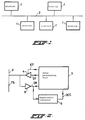
- FIG. 2 shows a diagram of an embodiment of a station 1.
- a station 1 comprises a data-processing unit 3, a transmitter circuit 4, a reception circuit 5 and a monostable multivibrator 6.
- the data-processing unit 3 is suitable for supplying an enable transmission signal ET and a serial data transmission signal DT to inputs of the transmitter circuit 4.
- the data-processing unit 3 is suitable for receiving, at the output of the reception circuit 5, a serial data reception signal DR.
- the data-processing unit 3 is furthermore suitable for receiving an output signal OCC from the output of the monostable multivibrator 6.
- the output of the transmitter circuit 4 and the input of the reception circuit 5 are connected to the link 2.
- the output of the reception circuit 5 is further connected to a trigger input of the monostable multivibrator 6. Every time the monostable multivibrator 6 receives a falling edge of the signal DR on its trigger input, the vibrator 6 sets the output signal OCC high for the time required for transmitting a transmission word.
- a signal transmitted by the link 2 is hereinafter referred to as transmission signal TS.
- Figure 3a represents an example of the data transmission signal DT
- Figure 3b represents the output signal OCC of the vibrator 6 during transmission of the signal DT
- Figure 3c represents another example of a data transmission signal DT'
- Figure 3d represents the output signal of the vibrator 6 OCC' during transmission of the signal DT'.
- the proportions of the transmission durations of start and stop sections and of data words are chosen in such a way that the start and stop sections each have a length of one bit and each data word has a length of four bits. In reality, other numbers can be used.
- the transmission signal TS via the link 2 has a high level. For the sake of clarity this has also been assumed hereinafter for the data transmission signal DT. If the link 2 is free, which is detected in a manner explained hereinafter, the data-processing unit 3 is able to transmit the data transmission signal DT. To this end, the unit 3 sets the enable signal ET to such a level that the transmitter circuit 4 lets the data transmisison signal DT pass through. The transmission signal TS via the link 2 then becomes identical to the data transmission signal DT.
- Figure 3a shows an example of a data transmission signal DT and of the transmission signal TS, if let through, consisting of two transmission words of which the first commences at a time t0 with a low level of the start section which lasts until the time t1. This is followed by a data word of which all four bits are high. The high level is maintained during the stop bit of the transmission word beginning at the time t2, until the beginning at the time t3 of the following transmission word, which is identical to the first transmission word. The stop section of the second transmission word ends at the time t5, whereafter the link 2 is again at rest and maintains the high level.
- the data reception signal DR supplied by the reception circuit 5 to the processing unit 3 is identical to the transmission signal TS via the link 2 and therefore, in the example, to the data transmission signal DT. If the data reception signal DR goes from a high level to a low level, the monostable multivibrator 6 is triggered, as a result of which the output signal OCC thereof becomes high. The signal OCC remains high during the interval predetermined by the monostable multivibrator 6. The monostable multivibrator 6 is set in such a way that the interval with the high level of the signal OCC lasts longer than the time required for transmitting a transmission word.
- the interval time is based on and at least equal to the sum of the transmission time of a transmission word, the response time of a receiving station and the transmission transit time via the link. In the example shown in Figures 3a and 3b, the interval could then end at the time t4.
- the monostable multivibrator 6 is restarted, however, each time it receives a falling edge at its trigger input, therefore also at the time t3 at the beginning of the second transmission word.
- the interval for which the signal OCC is high therefore lasts until beyond the time t4 at which the interval would end without restarting, namely until a time t6 which is situated beyond the time t3 by an amount of time equal to the duration of the interval.
- the signal OCC Since after the second transmission word the signal DT contains no further transmission word, at least not within the time for which the signal OCC is high, the signal OCC may be regarded as a signal which indicates the occupied state of the link 2. Therefore, the signal OCC is hereinafter also referred to as occupation signal OCC.
- each station 1 can generate an occupation signal OCC of the same shape.
- the processing unit 3 of a station 1 which is not transmitting will in general not supply a data transmission signal DT and will disable the transmitter circuit 4 by means of a suitable level of the transmission enable signal ET. Only when the interval of occupation has elapsed and the occupation signal OCC is low, does this indicate to the last-mentioned processing unit 3 that it may supply a data transmission signal DT and may enable the transmitter circuit 4. Only a station for which a current received message is destined is entitled, after that message has elapsed and while OCC is still high, to transmit a message, as a result of which OCC remains high and transmission by other stations continues to be suppressed.
- each data word to be transmitted of the signal DT' has bits of different levels. Since the multistable multivibrator 6 restarts at each falling edge, the interval of occupation of occupied signal OCC' will be of longer duration than in the previous example, namely at most until time t7.
- Figure 4 shows a schematic of a station 1 in which an interval of occupation of an occupied signal OCC always ends after a predetermined time after transmission of the last data word of a transmission signal TS.
- the schematic of Figure 4 has been extended by another monostable multivibrator 7 and an OR gate 8.
- the monostable vibrator 7 is of a type which cannot be restarted while a started interval thereof is still running.
- the monostable multivibrator 7 receives the data reception signal DR on a trigger input and supplies, as the output signal, a start inhibit signal SI at an input of the OR gate, another input of which receives the data reception signal DR and whose output is connected to the trigger input of the vibrator 6.
- the output signal SI thereof becomes high during a predetermined interval having a duration which is inbetween the transmission duration of a start section plus a data word and the transmission duration of a transmission word plus a start section.
- Figure 5a shows an example of a data transmission signal DT'' of two transmission words, of which the bits of each data word may have different levels.
- the data words are therefore indicated by hatched rectangles.
- both monostable multivibrators 6 and 7 will start at the time t0, as a result of which the start inhibit signal SI and the occupation signal OCC become high.
- the start inhibit signal SI is high, the level at the output of the OR gate 8, irrespective of the value of the level of the data reception signal DR, will not change, and consequently the vibrator 6 cannot be restarted during said start inhibit interval.
- the output of the OR gate 8 is set from the high to the low level if the data reception signal DR is already low or becomes low thereafter.
- the monostable multivibrators 6 and 7 will therefore restart at the time t3, at the beginning of the second transmission word.
- the following and at the same time last inhibit interval of the signal SI will then remain high until the time t9, and the interval of occupation with the high level of the occupation signal OCC as shown in Figure 5c will end at the same time t5 as shown in Figure 3b, at least for the abovementioned settings of the intervals of the vibrators 6 and 7.
- the data-processing unit 3 of each station 1 preferably works with a program which is designed to enable the station 1 to operate in the manner explained hereinafter.
- each station 1 has been assigned a unique address.
- the program incorporates the address of the second station in a first message to be transmitted by the first station.
- the program therefore comprises a step which, after reception of a message, i.e. when the address of the station in question has been recognized in the transmission via the link 2, sends back a message.
- the program contains the requirement that the transmission of a message expected back must commence within a reaction interval which ends before the interval of occupation of the occupation signal OCC after transmission of the first message ends.
- the reaction interval ends at the latest at the time t7, and in the embodiment of Figure 4 at the latest at the time t6.
- the program can be provided with the requirement that an answering station incorporate, in the answer to be transmitted, its own address as the sender address.
- the stations 1 which simultaneously began to transmit a message will then either not receive an answer in time within the reaction interval, owing to a possible difference in the transmission duration of the different simultaneously transmitted messages, or receive an answer from an incorrect sender.
- a station 1 If a station 1 does not receive a message expected back after a transmission, or does not receive it in time or correctly, it repeats the transmission after a time interval has elapsed which, with a high probability, is very different for the different stations 1, and when the link is free. This prevents any repetition in the occurrence of said interference. Detection of the occurrence of a message sent back, via the data transmission signal DR, and the repetition of the transmission can be effected by the program in a simple manner. In so doing, the delay time can be generated afresh each time or can be a function of the address of the station in question, for example proportional to a value representing the address.
- the said interference may arise as a result of two or more simultaneous transmissions of messages which all originate from different stations 1 and which are all destined for the same different station 1. If the messages then moreover are of the same duration, the address of the destination station need not be corrupted by interference and the destination station would therefore, in spite of the collision, still send back a message, which could lead, in all the stations 1 which just previously transmitted simultaneously, to the wrong decision that the communication had taken place correctly.
- the program preferably incorporates in each message to be transmitted both a destination address and a sender address.
- the program of a processing unit 3 of a first station 1 which, by means of a first message, has initiated a communication with a second station 1, can check whether a second message received back originates from the last-mentioned second station 1, on the basis of which the program can decide whether the communication has taken place correctly. Since the second message contains only a single destination address, only a single station can recognize its own address as the destination address of the transmitted second message. As a result of the assumed interference occurring, the last-mentioned station need not be one of the stations which transmitted simultaneously, in which situation all the stations which each, by transmitting a first message, initiated a communication, will judge that the communication has not taken place correctly. Even in case the different first messages transmitted simultaneously were of equal duration and the destination address of all these messages was the same, all the first stations which transmitted simultaneously, except for at most one, will judge that the communication has not taken place correctly.
Landscapes
- Engineering & Computer Science (AREA)
- Computer Networks & Wireless Communication (AREA)
- Signal Processing (AREA)
- Mobile Radio Communication Systems (AREA)
Applications Claiming Priority (2)
| Application Number | Priority Date | Filing Date | Title |
|---|---|---|---|
| NL9300441 | 1993-03-11 | ||
| NL9300441A NL9300441A (nl) | 1993-03-11 | 1993-03-11 | Werkwijze voor het beveiligen van de integriteit van gegevens bij asynchrone transmissie over een gemeenschappelijke verbinding, en een communicatiestelsel voor toepassing van de werkwijze. |
Publications (1)
| Publication Number | Publication Date |
|---|---|
| EP0615366A1 true EP0615366A1 (de) | 1994-09-14 |
Family
ID=19862157
Family Applications (1)
| Application Number | Title | Priority Date | Filing Date |
|---|---|---|---|
| EP94200626A Withdrawn EP0615366A1 (de) | 1993-03-11 | 1994-03-10 | Verfahren und System zum Zugriff auf ein Übertragungsmedium bei asynchroner Übertragung |
Country Status (2)
| Country | Link |
|---|---|
| EP (1) | EP0615366A1 (de) |
| NL (1) | NL9300441A (de) |
Citations (2)
| Publication number | Priority date | Publication date | Assignee | Title |
|---|---|---|---|---|
| WO1982004366A1 (fr) * | 1981-06-05 | 1982-12-09 | Christian Ryckeboer | Procede et dispositif pour la communication serie asynchrone de type multipoints de plusieurs emetteurs-recepteurs logiques |
| EP0132644A2 (de) * | 1983-07-28 | 1985-02-13 | International Business Machines Corporation | Verfahren und Vorrichtung zur Schnittstellenbildung zwischen einem Vielfachzugriffsbus und Benutzergeräten |
-
1993
- 1993-03-11 NL NL9300441A patent/NL9300441A/nl not_active Application Discontinuation
-
1994
- 1994-03-10 EP EP94200626A patent/EP0615366A1/de not_active Withdrawn
Patent Citations (2)
| Publication number | Priority date | Publication date | Assignee | Title |
|---|---|---|---|---|
| WO1982004366A1 (fr) * | 1981-06-05 | 1982-12-09 | Christian Ryckeboer | Procede et dispositif pour la communication serie asynchrone de type multipoints de plusieurs emetteurs-recepteurs logiques |
| EP0132644A2 (de) * | 1983-07-28 | 1985-02-13 | International Business Machines Corporation | Verfahren und Vorrichtung zur Schnittstellenbildung zwischen einem Vielfachzugriffsbus und Benutzergeräten |
Non-Patent Citations (1)
| Title |
|---|
| K. CLEMENTS ET AL.: "Ultra-Low-Cost Network for Personal Computers", BYTE, October 1981 (1981-10-01), ST PETERBOROUGH US, pages 50 - 66 * |
Also Published As
| Publication number | Publication date |
|---|---|
| NL9300441A (nl) | 1994-10-03 |
Similar Documents
| Publication | Publication Date | Title |
|---|---|---|
| EP1022878B1 (de) | Vorrichtung zur Übertragung von Daten | |
| EP0074864B1 (de) | System und Verfahren für das Nachschlagen von Namen in einem lokalen Bereichsnetz-Datenübertragungssystem | |
| US4430651A (en) | Expandable and contractible local area network system | |
| US5440560A (en) | Sleep mode and contention resolution within a common channel medium access method | |
| US4410889A (en) | System and method for synchronizing variable-length messages in a local area network data communication system | |
| US5499247A (en) | Multiplex transmission system having plurality of nodes and common transmission line and using divided data areas | |
| US5383185A (en) | Method and apparatus for data collision detection in a multi-processor communication system | |
| US5289466A (en) | Multiplex transmission method | |
| JP3293824B2 (ja) | 複数加入者を有する1つのバスシステムにおける情報伝送方法及び装置 | |
| EP0539096B1 (de) | Multiplexübertragungsverfahren und Verfahren zur Synchronisation in einer Multiplexübertragung | |
| EP0615366A1 (de) | Verfahren und System zum Zugriff auf ein Übertragungsmedium bei asynchroner Übertragung | |
| JPH05122226A (ja) | 多重伝送方法 | |
| JP3280852B2 (ja) | ポーリング通信方法 | |
| JPH0722431B2 (ja) | 多重通信システム | |
| JP2626914B2 (ja) | 多元接続装置 | |
| JP3769896B2 (ja) | データ伝送システム | |
| CA2226421C (en) | Data transmission method and system therefor | |
| JP3337907B2 (ja) | 多重伝送システム | |
| CA2363980C (en) | Data transmission method and system therefor | |
| CA1208736A (en) | System and method for name-lookup in a local area network data communication system | |
| JPH06104904A (ja) | 信号伝送装置 | |
| JPH0630005A (ja) | 多重通信装置 | |
| JPH0695684B2 (ja) | 送信制御方法 | |
| JPH01130646A (ja) | データ転送方式 | |
| JPS63116538A (ja) | デ−タ送出再試行方式 |
Legal Events
| Date | Code | Title | Description |
|---|---|---|---|
| PUAI | Public reference made under article 153(3) epc to a published international application that has entered the european phase |
Free format text: ORIGINAL CODE: 0009012 |
|
| AK | Designated contracting states |
Kind code of ref document: A1 Designated state(s): CH DE FR GB LI NL SE |
|
| 17P | Request for examination filed |
Effective date: 19940824 |
|
| 17Q | First examination report despatched |
Effective date: 19970624 |
|
| STAA | Information on the status of an ep patent application or granted ep patent |
Free format text: STATUS: THE APPLICATION IS DEEMED TO BE WITHDRAWN |
|
| 18D | Application deemed to be withdrawn |
Effective date: 19971105 |