EP0622253B1 - Bandages pneumatiques radiaux - Google Patents
Bandages pneumatiques radiaux Download PDFInfo
- Publication number
- EP0622253B1 EP0622253B1 EP94302894A EP94302894A EP0622253B1 EP 0622253 B1 EP0622253 B1 EP 0622253B1 EP 94302894 A EP94302894 A EP 94302894A EP 94302894 A EP94302894 A EP 94302894A EP 0622253 B1 EP0622253 B1 EP 0622253B1
- Authority
- EP
- European Patent Office
- Prior art keywords
- belt
- tire
- tread
- reinforcing layer
- pneumatic radial
- Prior art date
- Legal status (The legal status is an assumption and is not a legal conclusion. Google has not performed a legal analysis and makes no representation as to the accuracy of the status listed.)
- Expired - Lifetime
Links
- 230000003014 reinforcing effect Effects 0.000 claims description 37
- 239000011324 bead Substances 0.000 claims description 6
- 238000000926 separation method Methods 0.000 description 12
- 238000000034 method Methods 0.000 description 6
- 238000005452 bending Methods 0.000 description 5
- 238000010008 shearing Methods 0.000 description 5
- 230000015572 biosynthetic process Effects 0.000 description 4
- 230000000052 comparative effect Effects 0.000 description 3
- 230000000694 effects Effects 0.000 description 3
- 238000010030 laminating Methods 0.000 description 2
- 229910000831 Steel Inorganic materials 0.000 description 1
- 230000002349 favourable effect Effects 0.000 description 1
- 238000012423 maintenance Methods 0.000 description 1
- 239000010959 steel Substances 0.000 description 1
- 238000004804 winding Methods 0.000 description 1
Images


Classifications
-
- B—PERFORMING OPERATIONS; TRANSPORTING
- B60—VEHICLES IN GENERAL
- B60C—VEHICLE TYRES; TYRE INFLATION; TYRE CHANGING; CONNECTING VALVES TO INFLATABLE ELASTIC BODIES IN GENERAL; DEVICES OR ARRANGEMENTS RELATED TO TYRES
- B60C11/00—Tyre tread bands; Tread patterns; Anti-skid inserts
- B60C11/0083—Tyre tread bands; Tread patterns; Anti-skid inserts characterised by the curvature of the tyre tread
-
- B—PERFORMING OPERATIONS; TRANSPORTING
- B60—VEHICLES IN GENERAL
- B60C—VEHICLE TYRES; TYRE INFLATION; TYRE CHANGING; CONNECTING VALVES TO INFLATABLE ELASTIC BODIES IN GENERAL; DEVICES OR ARRANGEMENTS RELATED TO TYRES
- B60C11/00—Tyre tread bands; Tread patterns; Anti-skid inserts
-
- B—PERFORMING OPERATIONS; TRANSPORTING
- B60—VEHICLES IN GENERAL
- B60C—VEHICLE TYRES; TYRE INFLATION; TYRE CHANGING; CONNECTING VALVES TO INFLATABLE ELASTIC BODIES IN GENERAL; DEVICES OR ARRANGEMENTS RELATED TO TYRES
- B60C3/00—Tyres characterised by the transverse section
- B60C3/04—Tyres characterised by the transverse section characterised by the relative dimensions of the section, e.g. low profile
-
- B—PERFORMING OPERATIONS; TRANSPORTING
- B60—VEHICLES IN GENERAL
- B60C—VEHICLE TYRES; TYRE INFLATION; TYRE CHANGING; CONNECTING VALVES TO INFLATABLE ELASTIC BODIES IN GENERAL; DEVICES OR ARRANGEMENTS RELATED TO TYRES
- B60C9/00—Reinforcements or ply arrangement of pneumatic tyres
- B60C9/18—Structure or arrangement of belts or breakers, crown-reinforcing or cushioning layers
- B60C9/20—Structure or arrangement of belts or breakers, crown-reinforcing or cushioning layers built-up from rubberised plies each having all cords arranged substantially parallel
-
- B—PERFORMING OPERATIONS; TRANSPORTING
- B60—VEHICLES IN GENERAL
- B60C—VEHICLE TYRES; TYRE INFLATION; TYRE CHANGING; CONNECTING VALVES TO INFLATABLE ELASTIC BODIES IN GENERAL; DEVICES OR ARRANGEMENTS RELATED TO TYRES
- B60C9/00—Reinforcements or ply arrangement of pneumatic tyres
- B60C9/18—Structure or arrangement of belts or breakers, crown-reinforcing or cushioning layers
- B60C9/26—Folded plies
- B60C9/263—Folded plies further characterised by an endless zigzag configuration in at least one belt ply, i.e. no cut edge being present
-
- Y—GENERAL TAGGING OF NEW TECHNOLOGICAL DEVELOPMENTS; GENERAL TAGGING OF CROSS-SECTIONAL TECHNOLOGIES SPANNING OVER SEVERAL SECTIONS OF THE IPC; TECHNICAL SUBJECTS COVERED BY FORMER USPC CROSS-REFERENCE ART COLLECTIONS [XRACs] AND DIGESTS
- Y10—TECHNICAL SUBJECTS COVERED BY FORMER USPC
- Y10T—TECHNICAL SUBJECTS COVERED BY FORMER US CLASSIFICATION
- Y10T152/00—Resilient tires and wheels
- Y10T152/10—Tires, resilient
- Y10T152/10495—Pneumatic tire or inner tube
- Y10T152/10765—Characterized by belt or breaker structure
- Y10T152/10783—Reinforcing plies made up from wound narrow ribbons
Definitions
- This invention relates to pneumatic radial tires, and more particularly to a pneumatic heavy duty radial tire for use with trucks and buses under a high internal pressure which avoids separation failure at the belt end by specifying the arrangement of cords constituting the belt.
- JP-Y-48-96259 discloses a tire wherein a belt having no cut surface of cord at its end is formed by bending cords slantly extended with respect to an equatorial plane of the tire at a widthwise end of the belt so as to zigzag extend in a circumferential direction of the tire for avoiding the occurrence of separation failure at the belt end.
- the cords are crossed with each other at the widthwise end of the belt and continuously extended at a bent state, so that there is caused no cord shifting between upper and lower belt layers at the belt end and hence the stretching of the belt end in the circumferential direction is very small as compared with the conventional belt structure wherein rubberized cord plies having a given width are laminated one upon the other so as to cross the cords of the upper and lower plies with each other. This is particularly conspicuous when using high elastic cords such as steel cord and the like.
- the distance or diameter from the rotational axis of the tire to the outer surface of a tread is smaller at a widthwise end of the tread than at the widthwise central portion of the tread, i.e. there is a difference in diameter between the tread end and the tread center, so that a shearing deformation in the circumferential direction is apt to be caused at the widthwise end of the tread locating within a ground contact area during running under load in the case of heavy duty pneumatic tires for trucks and buses having a large diameter difference.
- the shearing deformation creates a large slipping between the tread end surface and the road surface, and consequently bring about a so-called shoulder wear wherein the tread end is prematurely worn as compared with the other portion of the tread.
- the belt cord plies are laminated one upon the other so as to cross the cords of the upper and lower plies with each other, whereby stretching of the belt end in the circumferential direction is ensured to absorb the diameter difference between the central portion of the tread in the widthwise direction and the widthwise end thereof.
- a tire according to the preamble of claim 1 is known from EP-A-0 501 782.
- an object of the present invention to provide a pneumatic radial tire capable of controlling the occurrence of shoulder wear together with the avoidance of belt end separation.
- a pneumatic radial tire comprising a radial carcass toroidally extending between a pair of bead cores, a belt superimposed about the carcass, a belt reinforcing layer laid on the belt, and a tread laid thereon, in which the belt is formed by a zigzag and continuously extending rubberized strip containing one or more cords therein substantially in the circumferential direction of the tread so as to slantly extend with respect to an equatorial plane of the tire from one end to the other end at both side edges of the belt through a bent state at each side edge; and the belt reinforcing layer is constituted by arranging a rubberized cord ply containing a plurality of cords slantly arranged with respect to the equatorial plane in a region corresponding to at least a side region of the tread; and the belt and the belt reinforcing layer satisfy a relationship that a distance from an intersect between a normal line of a rotational axis
- the belt reinforcing layer is comprised of two rubberized cord plies, the cords of which plies being crossed with each other at an inclination cord angle with respect to the equatorial plane larger than that of the belt.
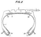
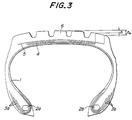
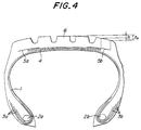
- Figs. 1 to 4 are shown various embodiments of pneumatic radial tires according to the invention.
- numeral 1 is a radial carcass toroidally extending between a pair of bead cores 2a and 2b.
- the carcass 1 is comprised of one carcass ply in the illustrated embodiments.
- the carcass 1 is provided about each of the bead cores 2a, 2b with three bead portion reinforcing layers 3a, 3b, two of which layers being turned around the bead core from outside of the tire to inside thereof.
- a belt 4, a belt reinforcing layer 5 (or 5a and 5b in Figs. 2 and 4) and a tread 6 are laid on the carcass 1 in the radial direction of the tire in this order.
- the belt 4 is formed by extending a rubberized strip 8 containing plural cords 7 (or a single cord) slantly arranged with respect to an equatorial plane O of the tire from one widthwise end of the belt to the other widthwise end thereof, bending at the other end so as to change the inclination with respect to the equatorial plane O in an opposite direction, extending from the other end to the one end, again bending at the one end so as to change the inclination with respect to the equatorial plane O in an opposite direction, and repeatedly conducting the above procedure to zigzag and continuously extend the strip substantially in the circumferential direction of the tire.
- the resulting belt 4 has a two-layer structure.
- the belt reinforcing layer 5 (or 5a, 5b) arranged outside the belt 4 is comprised of at least one rubberized cord ply containing plural cords arranged in parallel with each other.
- the belt reinforcing layer is formed by laminating two rubberized cord plies so as to cross the cords of these plies with each other, while the belt reinforcing layer in Figs. 3 and 4 is comprised of a single rubberized cord ply.
- the belt reinforcing layer 5 (or 5a, 5b) is arranged so as to cover each side portion of the tread including at least a tread end.
- the belt reinforcing layer 5 is arranged so as to cover a region corresponding to the full width of the tread, while the belt reinforcing layer 5a or 5b is arranged so as to cover only a region corresponding to each side portion of the tread.
- JP-Y-48-96259 discloses a method wherein a rubberized cord strip is returned 1-4 times by a given belt width in a rotating axial direction of the tire every winding in the circumferential direction of the tire and shifted by a given strip width before or after the wound strip in the circumferential direction every return to form a belt.
- a belt as shown in Fig. 5 can be obtained.
- the above method restricts the inclination cord angle with respect to the equatorial plane of the tire to a narrow range. Therefore, if it is intended to set the inclination cord angle within a favorable range from the viewpoint of performance in accordance with the width and circumferential length of the belt, it is desirable to adjust the inclination cord angle within a wider range.
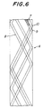
- the formation of the belt is carried out by determining a circumferential pitch for shifting a rubberized strip 8 containing one or more cords 7 therein before or after the wound strip in the circumferential direction so that an interval between a first wound strip 8 and next wound strip 8 is rendered into a given length by rotating the tire N times (integral number) every bending M times (integral number) at both belt ends as shown in Fig. 6.
- Fig. 6 is shown a state that the strip 8 is started from a position 9 and bent M times at both belt ends during the rotation of the tire N times to arrive at a position 10 adjacent to the starting point 9.
- the wound strip it is possible to arrange the wound strip at substantially a desired inclination cord angle with respect to the equatorial plane without generating a gap between the adjacent wound strips.
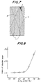
- the belt obtained by this method is shown in Fig. 7.
- a crossing line 11 apparently showing an interweave of the strip 8 is created as shown in Fig. 7.
- a belt obtained by laminating plural rubberized cord plies each containing a large number of cords therein so as to cross the cords of these plies with each other (hereinafter referred to as a conventional belt) is widely used and has cut surfaces of the cords at each ply end, so that there is a problem that belt end separation is easily caused starting from the cut surface of the cord.
- the zigzag belt creates no shifting of cord between upper and lower plies at the belt end and does not lower the belt tension at the belt end different from the conventional belt, so that it provides a hoop effect higher than that of the conventional belt.
- the inventors have examined the relation between the crown shape of the tread and the rigidity of the belt on the shoulder wear in detail and acquired the following knowledge.
- the zigzag belt is arranged in a region having a small diameter difference with respect to the central portion of the tread. Even if the width of the zigzag belt is made relatively narrow as compared with the conventional belt in order to develop the high hoop effect at the belt end, the zigzag belt can still maintain the carcass shape as a role of the belt. Further, when the belt width is made narrow, the rigidity in the circumferential direction at the shoulder portion of the tread can be reduced, whereby it is possible to absorb the diameter difference.
- a belt reinforcing layer made from a rubberized ply having a given width is arranged between the belt and the tread at a region ranging from at least an end portion of the belt to the tread end portion, whereby the movement of tread rubber at both sides of the belt is restrained to control the occurrence of shoulder wear.
- a distance h from an intersect between a normal line of a rotational axis of the tire passing through an outermost widthwise end of the belt and an outer surface of the tread to a position of maximum tire diameter is not more than 65% of a distance h 0 from an intersect between a normal line of a rotational axis of the tire passing through an outermost widthwise end of the belt reinforcing layer and an outer surface of the tread to the position of maximum tire diameter as shown in Figs. 1 to 4.
- the outermost end of the belt reinforcing layer in the widthwise direction of the belt is located near to the tread end portion, preferably within a range of 85-95% of a distance between both side ends of a ground contact area of the tread.
- the position of the outermost end of the belt may be determined from the outermost end of the belt reinforcing layer as a standard. If the width of the belt is too narrow, the maintenance of the carcass shape may be obstructed, so that it is preferable that the width of the belt is at least 50% of the maximum width of the carcass at radial section.
- the belt reinforcing layer has a two-ply structure of crossing cords of these plies with each other.
- the belt reinforcing layer is comprised of plural plies, if the inclination cord angle of the belt reinforcing layer with respect to the equatorial plane is small, the diameter difference at the tread end arranging the belt reinforcing layer becomes large and also the deformation of the belt reinforcing layer becomes large, so that the interlaminar shearing strain between the belt and the belt reinforcing layer increases to facilitate the occurrence of separation between the layers.
- it is desirable to reduce the interlaminar shearing strain by making the inclination cord angle of the belt reinforcing layer larger than that of the belt.
- the belt according to the invention has no cut surface of cord resulting in the occurrence of separation failure, even if the inclination cord angle of the belt is small, belt end separation hardly occurs. Therefore, the inclination cord angle of the belt with respect to the equatorial plane is preferably within a range of 10-30°. Moreover, sufficient hoop effect is obtained even if the width of the belt is narrow as previously mentioned.
- the inclination cord angle of the belt reinforcing layer is preferably larger by at least 5° than that of the belt or within a range of 20-50° with respect to the equatorial plane of the tire.
- Each of these test tires is mounted onto a rim of 7.5 x 22.5 size and inflated under an internal pressure of 7.5 kgf/cm 2 .
- Such a tire is mounted onto an idle shaft of a so-called 2D-4 vehicle in which two tires are mounted onto each side of a driving shaft and idle shaft on a rear wheel of the vehicle and run on a paved road under normal load over a distance of 20,000 km, and thereafter a worn state of the tread surface is measured.
- the measured results are also shown in Table 1, in which a value obtained by dividing an average of maximum worn depth in ribs at both tread ends by a maximum worn depth in a rib at the central portion of the tread is represented by an index of shoulder wear.
- pneumatic radial tires realizing control of shoulder wear together with avoidance of belt end separation and having an excellent durability.
Landscapes
- Engineering & Computer Science (AREA)
- Mechanical Engineering (AREA)
- Tires In General (AREA)
Claims (6)
- Pneumatique radial comprenant une carcasse radiale (1) s'étendant toroïdalement entre une paire de tringles (2a, 2b), une ceinture (4) superposée autour de la carcasse, et une bande de roulement (6) appliquée sur celle-ci, la ceinture (4) étant formée par une bande caoutchoutée s'étendant en zigzag et en continu (8), contenant un ou plusieurs câblés (7), pratiquement dans la direction circonférentielle de la bande de roulement, de sorte à être inclinés par rapport à un plan équatorial (O) du pneumatique, d'une extrémité vers l'autre extrémité au niveau des deux bords latéraux de la ceinture, par un pliage au niveau de chaque bord latéral; caractérisé en ce qu'une couche de renforcement de ceinture (5; 5a; 5b) est appliquée entre la ceinture et la bande de roulement, la couche de renforcement de ceinture (5; 5a; 5b) étant formée par agencement d'une nappe de câblés caoutchoutée contenant plusieurs câblés inclinés par rapport au plan équatorial dans une région correspondant au moins à une région latérale de la bande de roulement; la ceinture (4) et la couche de renforcement de ceinture (5; 5a; 5b) satisfaisant à une relation selon laquelle une distance (h), allant d'un point d'intersection entre une normale d'un axe de rotation du pneumatique, traversant l'extrémité la plus externe dans le sens de la largeur de la ceinture et une surface externe de la bande de roulement, vers une position correspondant au diamètre maximal du pneumatique, ne représente pas plus de 65% d'une distance (h0) allant d'un point d'intersection entre une normale d'un axe de rotation du pneumatique, traversant l'extrémité la plus externe dans le sens de la largeur de la couche de renforcement de ceinture et une surface externe de la bande de roulement vers la position correspondant au diamètre maximal du pneumatique.
- Pneumatique radial selon la revendication 1, caractérisé en ce que la couche de renforcement de ceinture (5; 5a; 5b) est composée de deux nappes de câblés caoutchoutées stratifiées, les câblés de ces nappes se croisant les uns les autres, et ayant un angle d'inclinaison des nappes par rapport au plan équatorial (O) supérieur à celui de la ceinture (4).
- Pneumatique radial selon les revendications 1 ou 2, caractérisé en ce que l'extrémité la plus externe de la couche de renforcement de ceinture (5; 5a; 5b) dans le sens de la largeur de la ceinture est agencée dans un intervalle représentant 85 à 95% d'une distance entre les extrémités d'une zone de contact au sol de la bande de roulement.
- Pneumatique radial selon l'une quelconque des revendications 1 à 3, caractérisé en ce que la largeur de la ceinture (4) représente au moins 50% de la largeur maximale de la carcasse (1) au niveau de la section radiale.
- Pneumatique radial selon l'une quelconque des revendications 1 à 4, caractérisé en ce que la ceinture (4) a un angle d'inclinaison des nappes de 10 à 30% par rapport au plan équatorial (O) du pneumatique.
- Pneumatique radial selon l'une quelconque des revendications 1 à 5, caractérisé en ce que la couche de renforcement de ceinture (5; 5a, 5b) a un angle d'inclinaison des nappes de 20 à 50° par rapport au plan équatorial (O) du pneumatique.
Applications Claiming Priority (2)
| Application Number | Priority Date | Filing Date | Title |
|---|---|---|---|
| JP104397/93 | 1993-04-30 | ||
| JP10439793 | 1993-04-30 |
Publications (2)
| Publication Number | Publication Date |
|---|---|
| EP0622253A1 EP0622253A1 (fr) | 1994-11-02 |
| EP0622253B1 true EP0622253B1 (fr) | 1996-10-09 |
Family
ID=14379604
Family Applications (1)
| Application Number | Title | Priority Date | Filing Date |
|---|---|---|---|
| EP94302894A Expired - Lifetime EP0622253B1 (fr) | 1993-04-30 | 1994-04-22 | Bandages pneumatiques radiaux |
Country Status (4)
| Country | Link |
|---|---|
| US (1) | US5465773A (fr) |
| EP (1) | EP0622253B1 (fr) |
| DE (1) | DE69400668T2 (fr) |
| ES (1) | ES2095717T3 (fr) |
Families Citing this family (18)
| Publication number | Priority date | Publication date | Assignee | Title |
|---|---|---|---|---|
| JPH04173404A (ja) * | 1990-11-06 | 1992-06-22 | Sumitomo Rubber Ind Ltd | 空気入りタイヤ |
| JPH07242105A (ja) * | 1994-03-04 | 1995-09-19 | Bridgestone Corp | 重荷重用空気入りタイヤ |
| US5636641A (en) | 1994-07-25 | 1997-06-10 | Advanced Cardiovascular Systems, Inc. | High strength member for intracorporeal use |
| JP3532981B2 (ja) * | 1994-12-13 | 2004-05-31 | 株式会社ブリヂストン | 空気入りラジアルタイヤ |
| US5837077A (en) * | 1995-08-18 | 1998-11-17 | The Yokohama Rubber, Co., Ltd. | Pneumatic vehicle tire having belt wound from flattened tubular tape |
| FR2757799B1 (fr) * | 1996-12-27 | 1999-02-05 | Michelin & Cie | Armature de sommet pour pneumatique d'avion |
| JP3198077B2 (ja) * | 1997-06-27 | 2001-08-13 | 住友ゴム工業株式会社 | 空気入りタイヤ |
| EP1072444B1 (fr) * | 1998-10-20 | 2006-08-30 | Bridgestone Corporation | Pneu radial resistant |
| FR2827221A1 (fr) * | 2001-07-16 | 2003-01-17 | Michelin Soc Tech | Pneumatique pour engin lourd |
| US20040154727A1 (en) * | 2003-02-11 | 2004-08-12 | Weissert James Thomas | Method and apparatus for manufacturing carcass plies for a tire |
| EP1977911B1 (fr) * | 2006-01-27 | 2011-05-25 | The Yokohama Rubber Co., Ltd. | Pneu a flancs renforces |
| US20090133797A1 (en) * | 2007-11-27 | 2009-05-28 | The Goodyear Tire & Rubber Company | Pneumatic tire |
| US8079392B2 (en) * | 2008-12-19 | 2011-12-20 | The Goodyear Tire & Rubber Company | Alternating straight/wavy reinforcement structure for pneumatic tire |
| US20100154974A1 (en) * | 2008-12-19 | 2010-06-24 | Francois Pierre Charles Gerard Georges | Method of making a pneumatic tire |
| US9168789B2 (en) | 2008-12-19 | 2015-10-27 | The Goodyear Tire & Rubber Company | Truck tire |
| US20100154964A1 (en) * | 2008-12-19 | 2010-06-24 | Francois Pierre Charles Gerard Georges | Pneumatic tire |
| US20100154965A1 (en) * | 2008-12-19 | 2010-06-24 | Roland Willibrord Krier | Offset zigzag belt structure for a pneumatic tire |
| FR3089454A3 (fr) * | 2018-12-05 | 2020-06-12 | Michelin & Cie | Pneumatique pour véhicule de Génie Civil, comprenant une armature de sommet à renforts métalliques trancannée |
Family Cites Families (18)
| Publication number | Priority date | Publication date | Assignee | Title |
|---|---|---|---|---|
| GB808341A (en) * | 1954-06-29 | 1959-02-04 | Dunlop Rubber Co | Improvements in or relating to pneumatic tyres |
| US3422874A (en) * | 1965-10-18 | 1969-01-21 | Deering Milliken Res Corp | Tire and method of making it by applying strip of rubber coated continuous tire cord of low extensibility to the carcass in flat form and simultaneously shaping and vulcanizing to final tire shape |
| US3550667A (en) * | 1967-12-27 | 1970-12-29 | Goodrich Co B F | Pneumatic tire |
| US3616001A (en) * | 1968-05-20 | 1971-10-26 | Deering Milliken Res Corp | Vibratory method for securing a continuous thread on a support surface |
| US3598166A (en) * | 1968-06-06 | 1971-08-10 | Deering Milliken Res Corp | Endless reinforcement for pneumatic tires |
| US3589426A (en) * | 1969-04-02 | 1971-06-29 | Deering Milliken Res Corp | Method for producing endless reinforcements for pneumatic tires |
| US3729365A (en) * | 1970-09-03 | 1973-04-24 | Deering Milliken Res Corp | Endless reinforcement and method for producing same |
| US3674079A (en) * | 1970-10-23 | 1972-07-04 | Deering Milliken Res Corp | Method for producing endless reinforcements for vulcanized pneumatic tires |
| US3748203A (en) * | 1971-04-12 | 1973-07-24 | Deering Milliken Res Corp | Method and apparatus for positioning a plurality of continuous stripson a support surface |
| JPS5439981B2 (fr) * | 1972-03-24 | 1979-11-30 | ||
| US4002789A (en) * | 1974-01-10 | 1977-01-11 | Deering Milliken Research Corporation | Endless reinforcement |
| JPS54159902A (en) * | 1978-06-07 | 1979-12-18 | Toyo Tire & Rubber Co Ltd | Radial tire |
| US4600456A (en) * | 1984-08-02 | 1986-07-15 | Armstrong Rubber Company | Method and apparatus for forming woven endless tire reinforcing belts |
| US4838966A (en) * | 1986-11-12 | 1989-06-13 | The Armstrong Rubber Co. | Woven endless tire reinforcing belt and method for producing same |
| JPS6428007A (en) * | 1987-07-21 | 1989-01-30 | Sumitomo Rubber Ind | Pneumatic tire |
| JPH01223004A (ja) * | 1988-03-01 | 1989-09-06 | Bridgestone Corp | 高内圧・重荷重用空気入りラジアルタイヤ |
| FR2665121B1 (fr) * | 1990-07-27 | 1994-12-23 | Michelin & Cie | Pneumatique dote d'une bande de roulement ayant des nervures laterales dont la surface est radialement en retrait par rapport aux autres nervures. |
| JP2628939B2 (ja) * | 1991-02-28 | 1997-07-09 | 住友ゴム工業株式会社 | 空気入りタイヤ |
-
1994
- 1994-04-19 US US08/229,749 patent/US5465773A/en not_active Expired - Lifetime
- 1994-04-22 ES ES94302894T patent/ES2095717T3/es not_active Expired - Lifetime
- 1994-04-22 DE DE69400668T patent/DE69400668T2/de not_active Expired - Lifetime
- 1994-04-22 EP EP94302894A patent/EP0622253B1/fr not_active Expired - Lifetime
Also Published As
| Publication number | Publication date |
|---|---|
| US5465773A (en) | 1995-11-14 |
| ES2095717T3 (es) | 1997-02-16 |
| EP0622253A1 (fr) | 1994-11-02 |
| DE69400668T2 (de) | 1997-02-27 |
| DE69400668D1 (de) | 1996-11-14 |
Similar Documents
| Publication | Publication Date | Title |
|---|---|---|
| EP0622253B1 (fr) | Bandages pneumatiques radiaux | |
| EP0595653B1 (fr) | Bandage pneumatique | |
| EP0484075B1 (fr) | Pneumatique radial pour moto | |
| EP0887208A2 (fr) | Bandage pneumatique | |
| US7789120B2 (en) | Tire having a composite belt structure | |
| EP0346106A1 (fr) | Bandage pneumatique | |
| EP0736400B1 (fr) | Pneumatiques à carcasse radiale pour poids lourds | |
| EP0531136B1 (fr) | Pneumatiques à carcasse radiale capables de performances élevées | |
| EP1201464B1 (fr) | Bandages pneumatiques radiaux | |
| EP1481821B1 (fr) | Bandage pneumatique radial | |
| EP0488734B1 (fr) | Bandage pneumatique radial pour voiture de tourisme | |
| EP2476544B1 (fr) | Pneu et procédé de formation de couche à courroie circonférentielle correspondante | |
| US6708747B1 (en) | Pneumatic radial tires | |
| JPH07112763B2 (ja) | 空気入りラジアルタイヤ | |
| JPH03204307A (ja) | 乗用車用ラジアルタイヤ | |
| EP0716940B1 (fr) | Bandages pneumatiques radiaux | |
| EP0755811A2 (fr) | Pneumatique pour véhicules à deux roues | |
| EP0541368B1 (fr) | Pneumatiques à carcasse radiale pour véhicules à deux roues | |
| EP0486274B1 (fr) | Pneumatique radial | |
| JP3495081B2 (ja) | 空気入りラジアルタイヤ | |
| EP0835768B1 (fr) | Bandages pneumatiques | |
| EP1211103B1 (fr) | Pneumatique avec une ceinture segmentée | |
| JPH07323703A (ja) | 空気入りラジアルタイヤ | |
| JPH03220001A (ja) | 高速走行用空気入りラジアルタイヤ | |
| JPH05330310A (ja) | 空気入りタイヤ |
Legal Events
| Date | Code | Title | Description |
|---|---|---|---|
| PUAI | Public reference made under article 153(3) epc to a published international application that has entered the european phase |
Free format text: ORIGINAL CODE: 0009012 |
|
| AK | Designated contracting states |
Kind code of ref document: A1 Designated state(s): DE ES FR GB IT |
|
| 17P | Request for examination filed |
Effective date: 19941017 |
|
| 17Q | First examination report despatched |
Effective date: 19951117 |
|
| GRAH | Despatch of communication of intention to grant a patent |
Free format text: ORIGINAL CODE: EPIDOS IGRA |
|
| GRAH | Despatch of communication of intention to grant a patent |
Free format text: ORIGINAL CODE: EPIDOS IGRA |
|
| GRAA | (expected) grant |
Free format text: ORIGINAL CODE: 0009210 |
|
| AK | Designated contracting states |
Kind code of ref document: B1 Designated state(s): DE ES FR GB IT |
|
| ITF | It: translation for a ep patent filed | ||
| REF | Corresponds to: |
Ref document number: 69400668 Country of ref document: DE Date of ref document: 19961114 |
|
| ET | Fr: translation filed | ||
| REG | Reference to a national code |
Ref country code: ES Ref legal event code: FG2A Ref document number: 2095717 Country of ref document: ES Kind code of ref document: T3 |
|
| PLBE | No opposition filed within time limit |
Free format text: ORIGINAL CODE: 0009261 |
|
| STAA | Information on the status of an ep patent application or granted ep patent |
Free format text: STATUS: NO OPPOSITION FILED WITHIN TIME LIMIT |
|
| 26N | No opposition filed | ||
| REG | Reference to a national code |
Ref country code: GB Ref legal event code: IF02 |
|
| PGFP | Annual fee paid to national office [announced via postgrant information from national office to epo] |
Ref country code: GB Payment date: 20100325 Year of fee payment: 17 |
|
| PGFP | Annual fee paid to national office [announced via postgrant information from national office to epo] |
Ref country code: ES Payment date: 20100423 Year of fee payment: 17 |
|
| PGFP | Annual fee paid to national office [announced via postgrant information from national office to epo] |
Ref country code: IT Payment date: 20100421 Year of fee payment: 17 Ref country code: DE Payment date: 20100430 Year of fee payment: 17 |
|
| PGFP | Annual fee paid to national office [announced via postgrant information from national office to epo] |
Ref country code: FR Payment date: 20110426 Year of fee payment: 18 |
|
| REG | Reference to a national code |
Ref country code: DE Ref legal event code: R119 Ref document number: 69400668 Country of ref document: DE |
|
| REG | Reference to a national code |
Ref country code: DE Ref legal event code: R119 Ref document number: 69400668 Country of ref document: DE |
|
| GBPC | Gb: european patent ceased through non-payment of renewal fee |
Effective date: 20110422 |
|
| PG25 | Lapsed in a contracting state [announced via postgrant information from national office to epo] |
Ref country code: IT Free format text: LAPSE BECAUSE OF NON-PAYMENT OF DUE FEES Effective date: 20110422 Ref country code: GB Free format text: LAPSE BECAUSE OF NON-PAYMENT OF DUE FEES Effective date: 20110422 |
|
| REG | Reference to a national code |
Ref country code: ES Ref legal event code: FD2A Effective date: 20120524 |
|
| PG25 | Lapsed in a contracting state [announced via postgrant information from national office to epo] |
Ref country code: ES Free format text: LAPSE BECAUSE OF NON-PAYMENT OF DUE FEES Effective date: 20110423 |
|
| REG | Reference to a national code |
Ref country code: FR Ref legal event code: ST Effective date: 20121228 |
|
| PG25 | Lapsed in a contracting state [announced via postgrant information from national office to epo] |
Ref country code: FR Free format text: LAPSE BECAUSE OF NON-PAYMENT OF DUE FEES Effective date: 20120430 |
|
| PG25 | Lapsed in a contracting state [announced via postgrant information from national office to epo] |
Ref country code: DE Free format text: LAPSE BECAUSE OF NON-PAYMENT OF DUE FEES Effective date: 20111031 |