EP0623920B1 - Disque optique, appareil de lecture de celui-ci ainsi que méthode d'enregistrement et de lecture de celui-ci - Google Patents
Disque optique, appareil de lecture de celui-ci ainsi que méthode d'enregistrement et de lecture de celui-ci Download PDFInfo
- Publication number
- EP0623920B1 EP0623920B1 EP94303138A EP94303138A EP0623920B1 EP 0623920 B1 EP0623920 B1 EP 0623920B1 EP 94303138 A EP94303138 A EP 94303138A EP 94303138 A EP94303138 A EP 94303138A EP 0623920 B1 EP0623920 B1 EP 0623920B1
- Authority
- EP
- European Patent Office
- Prior art keywords
- information
- basis
- surface deformed
- optical disc
- detection signals
- Prior art date
- Legal status (The legal status is an assumption and is not a legal conclusion. Google has not performed a legal analysis and makes no representation as to the accuracy of the status listed.)
- Expired - Lifetime
Links
- 230000003287 optical effect Effects 0.000 title claims description 61
- 238000000034 method Methods 0.000 title claims description 23
- 238000001514 detection method Methods 0.000 claims description 33
- 230000001678 irradiating effect Effects 0.000 claims description 8
- 239000000758 substrate Substances 0.000 claims description 6
- 102100036464 Activated RNA polymerase II transcriptional coactivator p15 Human genes 0.000 description 10
- 101000713904 Homo sapiens Activated RNA polymerase II transcriptional coactivator p15 Proteins 0.000 description 10
- 229910004444 SUB1 Inorganic materials 0.000 description 10
- 238000010586 diagram Methods 0.000 description 10
- 101150023658 SUB4 gene Proteins 0.000 description 9
- 230000014509 gene expression Effects 0.000 description 6
- 239000004065 semiconductor Substances 0.000 description 5
- 239000012634 fragment Substances 0.000 description 4
- 238000003909 pattern recognition Methods 0.000 description 3
- 101150080287 SUB3 gene Proteins 0.000 description 2
- 238000004364 calculation method Methods 0.000 description 2
- 238000010276 construction Methods 0.000 description 2
- 229920005668 polycarbonate resin Polymers 0.000 description 2
- 239000004431 polycarbonate resin Substances 0.000 description 2
- 229910004438 SUB2 Inorganic materials 0.000 description 1
- 101100311330 Schizosaccharomyces pombe (strain 972 / ATCC 24843) uap56 gene Proteins 0.000 description 1
- 229910052782 aluminium Inorganic materials 0.000 description 1
- XAGFODPZIPBFFR-UHFFFAOYSA-N aluminium Chemical compound [Al] XAGFODPZIPBFFR-UHFFFAOYSA-N 0.000 description 1
- 238000006243 chemical reaction Methods 0.000 description 1
- 238000007796 conventional method Methods 0.000 description 1
- 239000000284 extract Substances 0.000 description 1
- 230000006870 function Effects 0.000 description 1
- 229910052751 metal Inorganic materials 0.000 description 1
- 239000002184 metal Substances 0.000 description 1
- 230000002093 peripheral effect Effects 0.000 description 1
- 101150018444 sub2 gene Proteins 0.000 description 1
Images


Classifications
-
- G—PHYSICS
- G11—INFORMATION STORAGE
- G11B—INFORMATION STORAGE BASED ON RELATIVE MOVEMENT BETWEEN RECORD CARRIER AND TRANSDUCER
- G11B7/00—Recording or reproducing by optical means, e.g. recording using a thermal beam of optical radiation by modifying optical properties or the physical structure, reproducing using an optical beam at lower power by sensing optical properties; Record carriers therefor
- G11B7/12—Heads, e.g. forming of the optical beam spot or modulation of the optical beam
- G11B7/13—Optical detectors therefor
- G11B7/131—Arrangement of detectors in a multiple array
-
- G—PHYSICS
- G11—INFORMATION STORAGE
- G11B—INFORMATION STORAGE BASED ON RELATIVE MOVEMENT BETWEEN RECORD CARRIER AND TRANSDUCER
- G11B7/00—Recording or reproducing by optical means, e.g. recording using a thermal beam of optical radiation by modifying optical properties or the physical structure, reproducing using an optical beam at lower power by sensing optical properties; Record carriers therefor
- G11B7/004—Recording, reproducing or erasing methods; Read, write or erase circuits therefor
- G11B7/005—Reproducing
-
- G—PHYSICS
- G11—INFORMATION STORAGE
- G11B—INFORMATION STORAGE BASED ON RELATIVE MOVEMENT BETWEEN RECORD CARRIER AND TRANSDUCER
- G11B7/00—Recording or reproducing by optical means, e.g. recording using a thermal beam of optical radiation by modifying optical properties or the physical structure, reproducing using an optical beam at lower power by sensing optical properties; Record carriers therefor
- G11B7/24—Record carriers characterised by shape, structure or physical properties, or by the selection of the material
- G11B7/2407—Tracks or pits; Shape, structure or physical properties thereof
- G11B7/24085—Pits
- G11B7/24088—Pits for storing more than two values, i.e. multi-valued recording for data or prepits
Definitions
- the present invention is related with an optical disc, an apparatus for reproducing the optical disc, and a method of recording and reproducing the optical disc.
- the reproducing apparatus when music and image information is recorded on an optical disc 92, the information is converted into a signal, which parameter is a pit length of an information pit 91 on an information recording surface 95.
- the reproducing apparatus irradiates a laser light onto the information pit 91 to form a laser beam light spot LS having a predetermined diameter, detects the diffracted and reflected light by a light detector, which consists of a photodiode etc., and outputs it as an electric signal. Then, the reproducing apparatus extracts the recorded music and image information out of this electric signal by applying a signal conversion process contrary to the process at the time of recording, and outputs it.
- the compact disc (CD), the laser video disc (LVD) etc. are known as such an optical disc.
- a reference numeral 93 represents a substrate, which consists of polycarbonate resin etc.
- a reference numeral 94 represents a protection layer.
- the signal is read out by use of the change in the reflected light quantity depending on the existence of the pit at the time of scanning the optical beam on the optical disc.
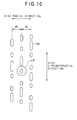
- the information recording density is greatly influenced by the value of a track pitch P 1 i.e. the interval between adjacent turns of the track each of which is a center line of the pit array of the information pit 91 as shown in FIG. 10, and the value of the diameter of the beam spot LS of the laser light irradiated onto the information pit 91.
- the track pitch should be made wide enough with respect to the diameter of the beam spot LS, resulting in the obstacle to high density recording of the optical disc.
- the diameter of the beam spot LS of the laser light is further reduced.
- the wavelength ⁇ may be reduced or the numerical aperture NA may be increased.
- the minimum track pitch which does not cause the crosstalk becomes about 1.6 ⁇ m. This value is employed by many optical discs presently available.
- European Patent 0553573 published on 04.08.93 discloses an optical disc having an information recording surface including a track (T) spirally formed on said surface, with a plurality of information units (U) formed on said track each having predetermined unit lengths (L) in both the disc peripheral direction and the disc radial direction. The information is recorded in the form of an information pit in each of the information units.
- the information pits have a plurality of pit patterns each of which is formed as combination of pit fragments (PP) having the substantially same shape.
- the combination of the fragments (PP) is, however, limited to sixteen patterns of information pits including a case of using no pit fragment (O) to a case of using all pit fragments (F).
- an object of the present invention to provide an optical disc, an apparatus for reproducing the optical disc, and a method of recording and reproducing the optical disc, which enables high density recording by a simple construction even under the condition of the laser light wavelength and the numerical aperture of the objective lens, which are presently available.
- an optical disc comprising: a substrate in a disc shape having an information record surface on which information is recorded; a track (T) spirally formed on the information record surface in a circumferential direction of the optical disc, and having a predetermined track pitch in a radial direction of the optical disc, a plurality of information units (U) arranged in the circumferential direction on the track, each unit having a square shape, a predetermined unit length in the circumferential direction and a predetermined unit length in the radial direction; and a plurality of surface deformed portions, each of which is formed in one of the information units respectively and comprises a plurality of surface deformed pieces (p) having substantially the same form as each other, characterized in that the surface deformed portions having at least M kinds of forms (M ⁇ 2, M: natural number), which are different, in directions of M kinds on a plane of the information record surface, from each other by a combination of existences of the surface deformed pieces, each of the surface deformed portions having a plane
- the above object of the present invention can be also achieved by an apparatus for reproducing the above described optical disc of the present invention.
- the reproducing apparatus is provided with a light irradiating means for irradiating a laser light having a predetermined wavelength onto the information record surface under an optical condition of a predetermined numerical aperture; an optical detecting means having M x K divided light receiving surfaces (K: natural number) such that a line parallel to the disc circumferential direction corresponds to one of division lines, for converting light incident on the light receiving surfaces into electric signals to output light detection signals respectively; an optical system for directing the reflected laser light, which is diffracted and reflected by the surface deformed portions onto a centre portion of the light receiving surface in case that the laser light is irradiated onto a centre line of the track; and an operating means for obtaining an information signal corresponding to the form of the surface deformed portion on the basis of the light detection signals to output the information signal; wherein the operating means includes means for obtaining the symmetrical axis of the surface deformed portion
- the above object of the present invention can be also achieved by a method of recording and reproducing the above described optical disc, provided with the steps of: irradiating a laser light having a predetermined wavelength onto the information record surface under an optical condition of a predetermined numerical aperture; directing the reflected laser light, which is diffracted and reflected by the surface deformed portions, onto a centre portion of M x K divided light receiving surfaces (K: natural number) of an optical detecting means in which a line parallel to the disc circumferential direction corresponds to one of division lines, in case that the laser light is irradiated onto a centre line of the track; converting light incident on the light receiving surfaces into electric signals to output light detection signals respectively, by the optical detecting means; and obtaining an information signal corresponding to the information converted into the form of the surface deformed portion on the basis of the light detection signals; wherein in the information signal obtaining step, the symmetrical axis of the surface deformed portion and the direction of the surface deformed portion are firstly obtained on the basis of the light detection
- high density recording is performed by making two or more pieces of information be recorded by one surface deformed portion (for example, a pit).
- various forms, which are distinguished to each other, are given to the pits as a method of recording information on the optical disc by a high density.
- 8 kinds of forms, which are distinguished to each other, are utilized, 8 kinds (3 bits) of information can be recorded in one pit, so that compared with the conventional method of detecting only the existence of a pit, a high density record can be realized.
- each of the pit may be arranged in such a state that the center of the pit is shifted from a center of a reading laser light to a certain direction, which is defined as the direction of the pit.
- the pits have 4 kinds of directions, and are distinguished and detected as different pits respectively which directions differ from each other. Further, for example, the pits, which directions are the same to each other but which sizes are different from each other, are different from each other in the reflected light quantity, so that the pits can be further distinguished and detected as different pits by use of the reflected light quantity.
- the directions of the pits are M kinds, and the sizes of the pits are N kinds, there exist M ⁇ N kinds of the distinguishable pits, so that M ⁇ N kinds of information can be held by one pit.
- FIG. 1A indicates an external appearance of a compact disc as an optical disc, for example.
- One track T is formed on a compact disc 1.
- the track T is in a spiral shape on the whole, which goes to the outer circumferential side from the inner circumferential side of the disc.
- FIG. 1B indicates a cross section of the compact disc 1 of FIG. 1A.
- the compact disc 1 includes a transparent substrate 2, which consists of polycarbonate resin etc..
- An information pit 4 as a surface deformed portion is formed on one surface i.e. an information record surface 3 of the substrate 2.
- the surface of the substrate 2 on which the pit 4 is formed i.e. the information record surface 3, is covered with a metal vapor deposited film as a reflection film 5, such as aluminum, and further covered with a protection layer 6.
- an arrow 7 indicates the direction in which a reading beam is irradiated.
- high density recording is performed by making two or more pieces of information be held by one pit 4.
- it will be explained in full detail, with referring to FIGs. 2A to 2C, and FIG. 3.
- FIG. 2A The relationship between the pit and the reading beam is shown in FIG. 2A, in which a pit P is arranged in such a state that the center thereof is shifted from a center O of a reading beam LS to a certain direction D.
- the direction D is defined as the direction of the pit P.
- the pits having 4 kinds of directions are shown in FIG. 2B, in which each of the pits I to IV is distinguished and detected respectively as a pit which direction D differs from each other.
- FIG. 2B the pits having 4 kinds of directions
- the pits I, II and III which directions are the same to each other but which sizes are different from each other, are different from each other in the reflected light quantity, they can be distinguished and detected as different pits by use of the reflected light quantity as well as the direction of the pit.
- the directions of the pits are M kinds, and the sizes of the pits are N kinds, there exist M ⁇ N kinds of the distinguishable pits, so that M ⁇ N kinds of information can be held by one pit.
- 16 kinds of the distinguishable pits are formed from one pit.
- the pit of A1 type consists of 5 pieces of the pit pieces p smeared with black in the figure, which direction is "->" and which size is "large”.
- the whole area around each pit enclosed by the dotted line is defined as an information unit U, and a position C of a x mark is defined as a center point of the information unit.
- FIG. 4A and FIG. 4B indicate the information unit U and a detector 30 for optical detection, respectively.
- the pit has a form symmetrical with respect to one of axes AA', BB', CC' and DD'. Therefore, the intensity distribution on the detector 30 is supposed to have a form symmetrical with respect to one of axes aa', bb', cc' and dd' in FIG. 4B. Therefore, the detection of the symmetrical axis i.e. detecting which axis it is symmetrical with respect to, is performed as the first stage of the detection.
- the direction of the pit is limited in two directions. For example, if the symmetrical axis is the axis cc', the direction of the pit is either upward or downward. It is the second stage of the detection to decide one of those two directions.
- FIG. 5 indicates the detector 30, which consists of eight detector pieces 8-1 to 8-8, and an operating circuit 32, which includes four information signal operating units 9-1 to 9-4.
- Detection signals d 1 to d 8 of the optical intensity from the eight detector pieces 8-1 to 8-8 are supplied to the operating circuit 32.
- the information signal operating units 9-1 to 9-4 in the operating circuit 32 carry out the process of the detection signals d 1 to d 8 according to following expressions (4) to (7), to output difference signals SUB1 to SUB4 respectively.
- the operating circuit 32 has a focus error signal operating unit 50, which will be mentioned later.
- SUB1 (d 1 + d 2 + d 3 + d 4 ) - (d 5 + d 6 + d 7 + d 8 ) ...
- the symmetrical axis is detected by finding the minimum value of the signals
- the symmetrical axis will be the axis cc' if the signal
- the intensity difference in the direction of the symmetrical axis is taken into consideration. It is enough to compare the intensities of the upper half of the detector (d 3 +d 4 +d 5 +d 6 ) and the lower half of the detector (d 7 +d 8 +d 1 +d 2 ), since the symmetrical axis is the axis cc' in the present example. Namely, it is judged whether the pit is in the upward direction or the downward direction by checking the + sign of the difference signal SUB3.
- the calculation is performed on the basis of a scaler analysis theory.
- the arrangement of the pits is shown in FIG. 6.
- a center pit is a pit 4 which is to be read, and pits having various forms are arranged around it.
- the reference mark LS represents the reading beam.
- Unit Interval ( ⁇ ) 1.20 ⁇ m
- Unit Length ( ⁇ ) 0.75 ⁇ m
- the pit 4 of A1 type shown in FIG. 3, is disposed at the center position.
- the calculated values are shown in FIG. 7.
- the values in FIG. 7 are values when the incident light quantity is normalized to 1.
- the method of detecting the pit becomes as in a following Table 2, according to the aforementioned rule of the present invention.
- the pits of A1 to A8 and B1 to B8 types can be distinguished from each other.
- FIG. 8 indicates a constitution of a compact disc player, which has the detector 30 and the operating circuit 32 of FIG. 5.
- a compact disc player 100 is provided with: an optical pickup 11 for reading information from a compact disc (CD) 1; a signal processing unit 12 for processing the read out information signal; a pickup controlling unit 13 for controlling the optical pickup 11; a system controller 14 for carrying out a generalization control of the compact disc player 100 on the whole; an inputting and displaying unit 15 by which various operation commands are inputted and various data are displayed; and a memory unit 16 for storing data necessary for the data process in the system controller 14.
- CD compact disc
- a signal processing unit 12 for processing the read out information signal
- a pickup controlling unit 13 for controlling the optical pickup 11
- a system controller 14 for carrying out a generalization control of the compact disc player 100 on the whole
- an inputting and displaying unit 15 by which various operation commands are inputted and various data are displayed
- a memory unit 16 for storing data necessary for the data process in the system controller 14.
- the optical pickup 11 is provided with: a semiconductor laser 21 for generating and irradiating a laser light; a collimator lens 22 for changing the irradiated laser light to a parallel beam; a beam splitter 23 for passing the parallel beam; a 1/4 wavelength plate 24 for giving an optical path difference of 1/4 wavelength to the parallel beam from the beam splitter 23; an objective lens 25 for condensing the laser light from the 1/4 wavelength plate 24 onto the information record surface 3 of the CD 1; a condenser lens 28 for condensing a reflected laser beam, which is reflected by the reflection film 5, passes through the objective lens 25 and the 1/4 wavelength plate 24, and which optical path is bent by a right angle at the reflection surface of the beam splitter 23; a prism mirror 29 for directing the reflected laser beam from the condenser lens 28 toward an eight divided photodetector 30; the eight divided photodetector 30 for receiving the reflected laser beam from the prism mirror 29; and a two divided photodetector 31 for receiving the reflected laser beam
- the signal processing unit 12 is provided with: an operating circuit 32 for receiving the output signals from the eight divided photodetector 30, giving a predetermined operation to the output signals, and outputting the results; a subtracter 33 for receiving the output signals from the two divided photodetector 31, and outputting the difference output as a tracking error signal TE; a digital signal processing circuit 34 for receiving the outputs from the operating circuit 32, applying a digital signal process, and demodulating to output information signals; a D/A converter 35 for converting the digital output from the digital signal processing circuit 34 to an analog signal; and output terminals 36L and 36R for outputting the output from the D/A converter 35 to the external; a semiconductor laser driving circuit 39D for driving the semiconductor laser 21; and a laser output controlling circuit 39 for controlling the semiconductor laser driving circuit 39D.
- the pickup controlling unit 13 is provided with: a tracking drive circuit 37 for receiving the tracking error signal TE, which is the output from the subtracter 33, and controlling a tracking actuator 26; and a focusing drive circuit 38 for controlling a focusing actuator 27 on the basis of the focusing error signal FE, which is another output of operating circuit 32.
- the system controller 14 controls the digital signal processing circuit 34, the tracking drive circuit 37 and the laser output controlling circuit 39 on the basis of the instructions from the inputting and displaying unit 15, and transmits and receives data to and from the memory unit 16.
- the more detailed constitutions of the eight divided photodetector 30 and the operating circuit 32 are shown in FIG. 5.
- the eight divided photodetector 30 has the eight light receiving areas i.e. the eight detector pieces 8-1 to 8-8.
- the operating circuit 32 has the information signal operating units 9-1 to 9-4, and the focus error signal operating unit 50.
- the information signals SUB1 to SUB4 are outputted from the information signal operating units 9-1 to 9-4, respectively.
- the focusing error signal FE is outputted from the focus error signal operating unit 50.
- the direction of the division line C-C' of the eight divided photodetector 30 is parallel to the circumferential direction of the disc.
- the optical system is constituted such that the center point of the reflected light spot is coincident with the center point of the eight divided photodetector 30, when the center of the laser spot from the objective lens is irradiated on the center line of the track.
- the photoelectrically converted light detection signals d 1 to d 8 are outputted from the respective eight divided light receiving areas i.e. the eight detector pieces 8-1 to 8-8 of the eight divided photodetector 30, and are inputted into the respective information signal operating units 9-1 to 9-4 and the focus error signal operating unit 50.
- the information signal operating units 9-1 to 9-4 process the respective detection signals d 1 to d 8 on the basis of the aforementioned expressions (4) to (7), and output the respective difference signals SUB1 to SUB4.
- the focus error signal operating unit 50 outputs the focusing error signal FE expressed by a following expression (8).
- FE d 1 + d 2 + d 5 + d 6 - (d 3 + d 4 + d 7 + d 8 )
- the pits can be distinguished on the basis of the difference signals SUB1 to SUB4 from the respective information signal operating units 9-1 to 9-4, as aforementioned.
- the pits are different in both of the direction and the size from each other, it becomes necessary to distinguish the pits on the basis of the difference signals SUB1 to SUB4 from the information signal operating units 9-1 to 9-4, as well as the whole light quantity SUM of the light detection signals d 1 to d 8 , as aforementioned.
- the operating circuit 32 of FIG. 8 is constructed to have a function of adding all of the light detection signals d 1 to d 8 and outputting the whole light quantity SUM.
- one surface deformed portion can hold many pieces of information by changing the direction of the form of the surface deformed portion. And, by changing not only the direction but also the size of the form of the surface deformed portion, one surface deformed portion can hold even more pieces of information. Therefore, high density recording becomes possible without narrowing the track pitch according to the present embodiment.
- the surface deformed portion can be distinguished by detecting the direction of the form of the surface deformed portion, the influence of the positional offset of the pattern of the surface deformed portion is little and the construction for detecting the surface deformed portion is rather simple as compared with the case where the pattern recognition of the pattern of the surface deformed portion itself is carried out.
Landscapes
- Physics & Mathematics (AREA)
- Optics & Photonics (AREA)
- Optical Recording Or Reproduction (AREA)
- Optical Record Carriers And Manufacture Thereof (AREA)
- Optical Head (AREA)
Claims (8)
- Disque optique (1) comprenant : un substrat (2) en forme de disque ayant une surface d'enregistrement d'informations (3), sur laquelle des informations sont enregistrées ; une piste (T) formée en spirale sur la surface d'enregistrement d'informations dans une direction circonférentielle du disque optique, et ayant un pas de piste prédéterminé dans une direction radiale du disque optique, une pluralité d'unités d'informations (U) disposées dans la direction circonférentielle sur la piste, chaque unité ayant une forme carrée, une longueur d'unité prédéterminée dans la direction circonférentielle et une longueur d'unité prédéterminée dans la direction radiale ; et une pluralité de parties de surface déformées (4), dont chacune est formée dans une des unités d'informations respectivement et comprend une pluralité d'éléments déformés de surface (p) ayant substantiellement la même forme que chaque autre, caractérisée en ce que les parties de surface déformées ayant au moins M sortes de formes (M > 2, M : un nombre naturel), qui sont différentes, en directions de M sortes sur un plan de la surface d'enregistrement d'informations, les unes des autres par une combinaison d'existences des éléments déformés de surface, chacune des parties de surface déformées ayant une forme de figure plane substantiellement symétrique par rapport à la ligne droite passant à travers un point central de l'unité d'informations comme un axe de symétrie, chacune des parties de surface déformées ayant une hauteur ou une profondeur optique prédéterminée ; où les parties de surface (4) ont M x N sortes de formes (N > 2, N : nombre naturel), qui sont différentes, en directions de M sortes et en dimensions de N sortes sur le plan de la surface d'enregistrement d'informations, les unes des autres par une combinaison d'existences des éléments déformés de surface.
- Disque optique selon la revendication 1 ; dans lequel chacune des unités d'informations (U) est divisée en 3 x 3 zones dans chacune desquelles un élément déformé de surface respectif (p) existe sélectivement ou n'existe pas en fonction des informations enregistrées.
- Disque optique selon la revendication 1 ou 2, dans lequel chacun des éléments déformés de surface (p) a une forme carrée sur le plan de la surface d'enregistrement d'informations.
- Disque optique selon l'une quelconque des revendications précédentes, dans lequel le disque optique comprend en outre un film de réflexion (5) couvrant la surface d'enregistrement d'informations, et une couche de protection (6) couvrant le film de réflexion.
- Appareil (100) pour reproduire un disque optique (1) selon l'une quelconque des revendications précédentes dans lequel l'appareil (100) comprend : un moyen d'irradiation de lumière (21, 22, 23, 24, 25) pour irradier une lumière laser ayant une longueur d'onde prédéterminée sur la surface d'enregistrement d'informations sous une condition optique d'une ouverture numérique prédéterminée ; un moyen de détection optique (30) ayant M x K surfaces divisés de réception de lumière (K : nombre naturel) pour qu'une ligne parallèle à la direction circonférentielle du disque corresponde à une des lignes de division, pour convertir l'incidence de lumière sur les surfaces de réception de lumière en signaux électriques pour fournir respectivement des signaux de détection de lumière ; un système optique (23, 24, 25, 28, 29) pour diriger la lumière laser réfléchie, qui est diffractée et réfléchie par les parties de surface déformées sur une partie centrale de la surface de réception de lumière dans le cas où la lumière laser est irradiée sur une ligne centrale de la piste ; et un moyen de fonctionnement (32) pour obtenir un signal d'informations correspondant à la forme de la partie de surface déformée sur la base des signaux de détection de lumière pour fournir le signal d'informations ; caractérisé en ce que le moyen de fonctionnement (32) comprend un moyen pour obtenir l'axe de symétrie de la partie de surface déformée sur la base des signaux de détection de lumière, et un moyen pour obtenir la direction de la partie de surface déformée sur la base des signaux de détection de lumière, le moyen de fonctionnement obtenant le signal d'informations sur la base de l'axe de symétrie obtenu et de la direction obtenue ; et où le moyen de fonctionnement (32) comprend en outre un moyen pour obtenir la dimension de la partie de surface déformée sur la base des signaux de détection de lumière.
- Appareil selon la revendication 5, dans lequel le moyen de fonctionnement (32) comprend un moyen (50) pour obtenir un signal d'erreur de focalisation (FE) sur la base des signaux de détection de lumière.
- Procédé d'enregistrement et de reproduction d'un disque optique (1) selon l'une quelconque des revendications 1 à 4, le procédé comprenant les étapes d'irradiation d'une lumière laser ayant une longueur d'onde prédéterminée sur la surface d'enregistrement d'informations sous une condition optique d'une ouverture numérique prédéterminée, de direction de la lumière laser réfléchie, qui est diffractée et réfléchie par les parties de surface déformées, sur une partie centrale de M x K surfaces de réception de lumière divisées (K : nombre naturel) d'un moyen de détection optique (30) où une ligne parallèle à la direction circonférentielle du disque correspond à une des lignes de division, dans le cas où la lumière laser est irradiée sur la ligne centrale de la piste ; conversion de la lumière incidente sur les surfaces de réception de lumière en signaux électriques pour fournir des signaux de détection de lumière respectivement, par le moyen de détection optique ; et obtention d'un signal d'informations correspondant aux informations converties sous la forme de la partie de surface déformée sur la base des signaux de détection de lumière ; où dans l'étape d'obtention du signal d'informations, l'axe de symétrie de la partie de surface déformée et la direction de la partie de surface déformée sont d'abord obtenus sur la base des signaux de détection de lumière, pour obtenir le signal d'informations sur la base de l'axe de symétrie obtenu et de la direction obtenue ; et où dans l'étape d'obtention du signal d'informations, la dimension de la partie de surface déformée est obtenue sur la base des signaux de détection de lumière.
- Procédé selon la revendication 7, dans lequel le procédé comprend en outre les étapes de :
obtention d'un signal d'erreur de focalisation (FE) sur la base des signaux de détection de lumière ; et la réalisation d'une commande de suivi de focalisation du disque optique sur la base du signal d'erreur de focalisation tout en détectant la lumière laser réfléchie.
Applications Claiming Priority (2)
| Application Number | Priority Date | Filing Date | Title |
|---|---|---|---|
| JP10571193A JP3224901B2 (ja) | 1993-05-06 | 1993-05-06 | 光ディスク、光ディスク再生装置及び光ディスクの記録再生方法 |
| JP105711/93 | 1993-05-06 |
Publications (2)
| Publication Number | Publication Date |
|---|---|
| EP0623920A1 EP0623920A1 (fr) | 1994-11-09 |
| EP0623920B1 true EP0623920B1 (fr) | 1999-02-24 |
Family
ID=14414927
Family Applications (1)
| Application Number | Title | Priority Date | Filing Date |
|---|---|---|---|
| EP94303138A Expired - Lifetime EP0623920B1 (fr) | 1993-05-06 | 1994-04-29 | Disque optique, appareil de lecture de celui-ci ainsi que méthode d'enregistrement et de lecture de celui-ci |
Country Status (4)
| Country | Link |
|---|---|
| US (1) | US5572508A (fr) |
| EP (1) | EP0623920B1 (fr) |
| JP (1) | JP3224901B2 (fr) |
| DE (1) | DE69416611T2 (fr) |
Families Citing this family (15)
| Publication number | Priority date | Publication date | Assignee | Title |
|---|---|---|---|---|
| JP2738337B2 (ja) * | 1995-03-31 | 1998-04-08 | 日本電気株式会社 | 光再生媒体の再生方法及び再生装置 |
| US5946288A (en) * | 1995-03-31 | 1999-08-31 | Nec Corporation | Optical recording medium having recording pits of different shapes |
| JP3159363B2 (ja) * | 1996-02-16 | 2001-04-23 | 日本電気株式会社 | 光再生媒体とその再生方法 |
| US6262954B1 (en) * | 1997-09-30 | 2001-07-17 | Kabushiki Kaisha Toshiba | Optical disk apparatus |
| WO1999034358A2 (fr) * | 1997-12-30 | 1999-07-08 | Lou David Y | Support d'enregistrement optique multidimensionnel et son appareil d'enregistrement et de reproduction |
| US6826143B1 (en) | 2000-01-14 | 2004-11-30 | Lucent Technologies Inc. | Multi-dimensional optical disk |
| US7522480B2 (en) | 2001-01-25 | 2009-04-21 | Dphi Acquisitions, Inc. | Digital tracking servo system with multi-track seek with an acceleration clamp |
| JP2006510143A (ja) * | 2002-12-12 | 2006-03-23 | コーニンクレッカ フィリップス エレクトロニクス エヌ ヴィ | 区分化光検出器を有するビット検出装置 |
| US7180834B2 (en) * | 2003-01-06 | 2007-02-20 | The Boeing Company | Apparatus and methods for digital data recording |
| US7345987B2 (en) * | 2003-01-21 | 2008-03-18 | Kenley Earl Brinkerhoff | Optical disc which stores digital information in informational units which diffract a line of laser light at one of 1024 angles and a corresponding light detecting apparatus for reproducing information from said optical disc |
| EP1683137A1 (fr) * | 2003-10-29 | 2006-07-26 | Koninklijke Philips Electronics N.V. | Appareil d'enregistrement et procede d'enregistrement d'informations sur un support d'enregistrement sous la forme de marquages creux |
| US20080008061A1 (en) * | 2004-05-13 | 2008-01-10 | Koninklijke Philips Electronics, N.V. | Spot Aberrations in a Two-Dimensional Optical Storage System |
| US20050281187A1 (en) * | 2004-06-17 | 2005-12-22 | Sharp Kabushiki Kaisha | Optical memory device and optical reproducing device |
| US20090238056A1 (en) * | 2004-12-13 | 2009-09-24 | Koninklijke Philips Electronics, N.V. | Optical storage effect using a separate reference beam interface |
| US9056422B2 (en) * | 2013-04-09 | 2015-06-16 | Massachusetts Institute Of Technology | Methods and apparatus for encoded textures |
Family Cites Families (13)
| Publication number | Priority date | Publication date | Assignee | Title |
|---|---|---|---|---|
| JPS59207433A (ja) * | 1983-05-12 | 1984-11-24 | Sony Corp | 高密度記録再生方式 |
| JPS63153743A (ja) * | 1986-07-10 | 1988-06-27 | Hitachi Maxell Ltd | 光情報記録媒体及びその製造方法 |
| JP2578459B2 (ja) * | 1988-01-25 | 1997-02-05 | キヤノン株式会社 | 情報記録媒体、情報記録媒体用基板の製造方法及び情報記録媒体用基板の成形用型 |
| US5249175A (en) * | 1988-09-09 | 1993-09-28 | Matsushita Electric Industrial Co., Ltd. | Optical information recording medium and information recording and reproducing method therefor |
| JPH03219434A (ja) * | 1988-12-27 | 1991-09-26 | Canon Inc | 光学的情報記録媒体 |
| JP2612329B2 (ja) * | 1988-12-27 | 1997-05-21 | シャープ株式会社 | 光メモリ素子並びに光メモリ再生装置 |
| NL9100408A (nl) * | 1991-03-07 | 1992-10-01 | Philips Nv | Informatie-uitleesstelsel, alsmede een registratiedrager en uitleesinrichting voor toepassing in een dergelijk stelsel. |
| JPH0528507A (ja) * | 1991-07-19 | 1993-02-05 | Pioneer Electron Corp | 光学式情報記録媒体およびその再生装置 |
| JP3173839B2 (ja) * | 1992-01-17 | 2001-06-04 | パイオニア株式会社 | 記録媒体用情報再生装置及び再生方法 |
| JP3067874B2 (ja) * | 1992-01-20 | 2000-07-24 | パイオニア株式会社 | 光ディスク、光ディスク再生装置及び光ディスクの記録再生方法 |
| US5331626A (en) * | 1992-01-20 | 1994-07-19 | Pioneer Electronic Corporation | Recording medium and information recording and reproducing apparatus therefor |
| JP3067873B2 (ja) * | 1992-01-20 | 2000-07-24 | パイオニア株式会社 | 光ディスク及び光ディスク再生装置 |
| JP3095871B2 (ja) * | 1992-04-09 | 2000-10-10 | パイオニア株式会社 | 光学式ディスクおよびその情報再生方法 |
-
1993
- 1993-05-06 JP JP10571193A patent/JP3224901B2/ja not_active Expired - Fee Related
-
1994
- 1994-04-29 EP EP94303138A patent/EP0623920B1/fr not_active Expired - Lifetime
- 1994-04-29 DE DE69416611T patent/DE69416611T2/de not_active Expired - Fee Related
-
1995
- 1995-09-18 US US08/529,788 patent/US5572508A/en not_active Expired - Fee Related
Also Published As
| Publication number | Publication date |
|---|---|
| EP0623920A1 (fr) | 1994-11-09 |
| JPH06318325A (ja) | 1994-11-15 |
| DE69416611T2 (de) | 1999-09-16 |
| US5572508A (en) | 1996-11-05 |
| DE69416611D1 (de) | 1999-04-01 |
| JP3224901B2 (ja) | 2001-11-05 |
Similar Documents
| Publication | Publication Date | Title |
|---|---|---|
| EP0623920B1 (fr) | Disque optique, appareil de lecture de celui-ci ainsi que méthode d'enregistrement et de lecture de celui-ci | |
| EP0219170B1 (fr) | Appareil de lecture ou d'enregistrement d'une structure d'information optique disposée en forme de piste | |
| US4800547A (en) | Optical record carrier scanning apparatus with scanning beam focus error detection | |
| US4011400A (en) | Apparatus for reading an optically readable reflecting information structure | |
| US5359591A (en) | Optical disc having information pits in form of plurality of fragments arranged in symmetrical pattern | |
| EP0881638B1 (fr) | Discriminateur de disque optique | |
| GB2059057A (en) | Photo-electric focussing error detection | |
| EP0661698A1 (fr) | Tête optique à superrésolution utilisant un séparateur optique | |
| EP0628954B1 (fr) | Méthode et appareil de reproduction et d'enregistrement d'information sur disque optique, et détecteur de lumière utilisé dans cet appareil | |
| US5717682A (en) | Optical disk having information pits of different lengths and shapes | |
| EP0633566B1 (fr) | Disque optique, appareil de reproduction d'un tel disque, et procédé d'enregistrement et reproduction de celui-ci | |
| JP3145751B2 (ja) | 光ピックアップ装置 | |
| US5953304A (en) | Optical disc recording or playback device with corrected focus optical scanning | |
| US4633454A (en) | Optical information pickup apparatus | |
| EP0762402A1 (fr) | Tête de lecture optique à lecture améliorée de milieus avec des creux de profondeurs différentes | |
| US20070247984A1 (en) | Optical Record Carrier and Optical Scanning Device | |
| US6788644B1 (en) | Devuce and method for forming a focus error signal based on ohase difference between corresponding parts of detector signals | |
| EP0292258B1 (fr) | Appareil d'enregistrement et de reproduction d'information optique | |
| US6781104B1 (en) | Device for scanning an optical record carrier | |
| EP1763876B1 (fr) | Procede et systeme pour la generation d'une erreur de signal d'aberration spherique | |
| US6347066B1 (en) | Optical pickup and optical disk apparatus | |
| JPS6310325A (ja) | 光学式ヘツド装置 | |
| JPH0636339A (ja) | 光学式再生装置 | |
| JPH02173939A (ja) | 光検出装置 | |
| JP2006004524A (ja) | 光メモリ素子および光再生装置 |
Legal Events
| Date | Code | Title | Description |
|---|---|---|---|
| PUAI | Public reference made under article 153(3) epc to a published international application that has entered the european phase |
Free format text: ORIGINAL CODE: 0009012 |
|
| AK | Designated contracting states |
Kind code of ref document: A1 Designated state(s): DE FR GB |
|
| 17P | Request for examination filed |
Effective date: 19950421 |
|
| 17Q | First examination report despatched |
Effective date: 19970709 |
|
| GRAG | Despatch of communication of intention to grant |
Free format text: ORIGINAL CODE: EPIDOS AGRA |
|
| GRAG | Despatch of communication of intention to grant |
Free format text: ORIGINAL CODE: EPIDOS AGRA |
|
| GRAH | Despatch of communication of intention to grant a patent |
Free format text: ORIGINAL CODE: EPIDOS IGRA |
|
| GRAH | Despatch of communication of intention to grant a patent |
Free format text: ORIGINAL CODE: EPIDOS IGRA |
|
| GRAA | (expected) grant |
Free format text: ORIGINAL CODE: 0009210 |
|
| AK | Designated contracting states |
Kind code of ref document: B1 Designated state(s): DE FR GB |
|
| REG | Reference to a national code |
Ref country code: GB Ref legal event code: 746 Effective date: 19990302 |
|
| REF | Corresponds to: |
Ref document number: 69416611 Country of ref document: DE Date of ref document: 19990401 |
|
| ET | Fr: translation filed | ||
| REG | Reference to a national code |
Ref country code: FR Ref legal event code: D6 |
|
| PLBE | No opposition filed within time limit |
Free format text: ORIGINAL CODE: 0009261 |
|
| STAA | Information on the status of an ep patent application or granted ep patent |
Free format text: STATUS: NO OPPOSITION FILED WITHIN TIME LIMIT |
|
| 26N | No opposition filed | ||
| REG | Reference to a national code |
Ref country code: GB Ref legal event code: IF02 |
|
| PGFP | Annual fee paid to national office [announced via postgrant information from national office to epo] |
Ref country code: FR Payment date: 20060410 Year of fee payment: 13 |
|
| PGFP | Annual fee paid to national office [announced via postgrant information from national office to epo] |
Ref country code: GB Payment date: 20060426 Year of fee payment: 13 |
|
| PGFP | Annual fee paid to national office [announced via postgrant information from national office to epo] |
Ref country code: DE Payment date: 20060427 Year of fee payment: 13 |
|
| GBPC | Gb: european patent ceased through non-payment of renewal fee |
Effective date: 20070429 |
|
| PG25 | Lapsed in a contracting state [announced via postgrant information from national office to epo] |
Ref country code: DE Free format text: LAPSE BECAUSE OF NON-PAYMENT OF DUE FEES Effective date: 20071101 |
|
| PG25 | Lapsed in a contracting state [announced via postgrant information from national office to epo] |
Ref country code: GB Free format text: LAPSE BECAUSE OF NON-PAYMENT OF DUE FEES Effective date: 20070429 |
|
| PG25 | Lapsed in a contracting state [announced via postgrant information from national office to epo] |
Ref country code: FR Free format text: LAPSE BECAUSE OF NON-PAYMENT OF DUE FEES Effective date: 20070430 |