EP0624778A1 - Dispositif de mesure de position - Google Patents
Dispositif de mesure de position Download PDFInfo
- Publication number
- EP0624778A1 EP0624778A1 EP94107106A EP94107106A EP0624778A1 EP 0624778 A1 EP0624778 A1 EP 0624778A1 EP 94107106 A EP94107106 A EP 94107106A EP 94107106 A EP94107106 A EP 94107106A EP 0624778 A1 EP0624778 A1 EP 0624778A1
- Authority
- EP
- European Patent Office
- Prior art keywords
- group
- magnetoresistive elements
- elements
- measuring device
- measuring
- Prior art date
- Legal status (The legal status is an assumption and is not a legal conclusion. Google has not performed a legal analysis and makes no representation as to the accuracy of the status listed.)
- Granted
Links
- 230000000737 periodic effect Effects 0.000 claims abstract description 5
- 238000005259 measurement Methods 0.000 claims description 10
- 238000011156 evaluation Methods 0.000 claims description 5
- 230000001419 dependent effect Effects 0.000 claims description 4
- 239000004020 conductor Substances 0.000 abstract description 6
- 239000000463 material Substances 0.000 description 4
- 230000002411 adverse Effects 0.000 description 1
- 230000003321 amplification Effects 0.000 description 1
- 238000010276 construction Methods 0.000 description 1
- 238000011161 development Methods 0.000 description 1
- 230000018109 developmental process Effects 0.000 description 1
- 230000000694 effects Effects 0.000 description 1
- 238000005516 engineering process Methods 0.000 description 1
- 238000004519 manufacturing process Methods 0.000 description 1
- 238000003199 nucleic acid amplification method Methods 0.000 description 1
- 238000005496 tempering Methods 0.000 description 1
Images


Classifications
-
- G—PHYSICS
- G01—MEASURING; TESTING
- G01D—MEASURING NOT SPECIALLY ADAPTED FOR A SPECIFIC VARIABLE; ARRANGEMENTS FOR MEASURING TWO OR MORE VARIABLES NOT COVERED IN A SINGLE OTHER SUBCLASS; TARIFF METERING APPARATUS; MEASURING OR TESTING NOT OTHERWISE PROVIDED FOR
- G01D5/00—Mechanical means for transferring the output of a sensing member; Means for converting the output of a sensing member to another variable where the form or nature of the sensing member does not constrain the means for converting; Transducers not specially adapted for a specific variable
- G01D5/12—Mechanical means for transferring the output of a sensing member; Means for converting the output of a sensing member to another variable where the form or nature of the sensing member does not constrain the means for converting; Transducers not specially adapted for a specific variable using electric or magnetic means
- G01D5/14—Mechanical means for transferring the output of a sensing member; Means for converting the output of a sensing member to another variable where the form or nature of the sensing member does not constrain the means for converting; Transducers not specially adapted for a specific variable using electric or magnetic means influencing the magnitude of a current or voltage
- G01D5/142—Mechanical means for transferring the output of a sensing member; Means for converting the output of a sensing member to another variable where the form or nature of the sensing member does not constrain the means for converting; Transducers not specially adapted for a specific variable using electric or magnetic means influencing the magnitude of a current or voltage using Hall-effect devices
- G01D5/145—Mechanical means for transferring the output of a sensing member; Means for converting the output of a sensing member to another variable where the form or nature of the sensing member does not constrain the means for converting; Transducers not specially adapted for a specific variable using electric or magnetic means influencing the magnitude of a current or voltage using Hall-effect devices influenced by the relative movement between the Hall device and magnetic fields
-
- G—PHYSICS
- G01—MEASURING; TESTING
- G01P—MEASURING LINEAR OR ANGULAR SPEED, ACCELERATION, DECELERATION, OR SHOCK; INDICATING PRESENCE, ABSENCE, OR DIRECTION, OF MOVEMENT
- G01P13/00—Indicating or recording presence, absence, or direction, of movement
- G01P13/02—Indicating direction only, e.g. by weather vane
- G01P13/04—Indicating positive or negative direction of a linear movement or clockwise or anti-clockwise direction of a rotational movement
Definitions
- the invention relates to a position measuring device according to the preamble of claim 1.
- Such a position measuring device is used in particular in a machine tool for measuring the relative position of a tool with respect to a workpiece to be machined.
- EP 0 151 002 B1 describes a magnetic position measuring device for measuring the relative position of two objects that are movable relative to one another, in which a periodic measurement division is scanned by a scanning unit according to FIG. 19 by means of two groups of four magnetoresistive elements each to generate zero-symmetrical output signals.
- the four magnetoresistive elements of the two groups with the output signals of the phase angles 0 ° and 180 ° become a first half-bridge circuit in the form of a series connection and the magnetoresistive elements of the two groups are connected to the output signals of the phase positions 90 ° and 270 ° in the form of a series circuit to form a second half-bridge circuit; at the center taps of the two half-bridge circuits there are two zero-symmetrical output signals with a mutual phase offset of 90 ° for obtaining position measurement values in a downstream evaluation device.
- This position measuring device has the disadvantage, however, that the connecting conductor tracks of the magnetoresistive elements cross one another several times, so that an insulating layer must be provided between the crossing connecting conductor tracks, which are applied in layering technology, and the necessary tempering of which causes an increase in the hysteresis of the two zero-symmetrical output signals.
- This additional provision of the insulating layer and the crossover layer makes the scanning unit more expensive and can lead to an increased scrap in production.
- DE-PS 37 19 328 shows a similar magnetic position measuring device, in which a periodic measurement division is scanned by a scanning unit according to FIG. 2A by means of four groups of four magnetoresistive elements each to produce zero-symmetrical output signals.
- the four magnetoresistive elements of each group are no longer arranged together within one division period of the measuring division; there is in particular between the magnetoresistive element with the output signal of the phase angle 0 ° and the magnetoresistive element with the output signal of the phase position 180 ° (push-pull elements) and between the magnetoresistive element with the output signal of the phase position 90 ° and the magnetoresistive element with the output signal of the phase position 270 ° (push-pull elements) of the same group in the measuring direction a distance of over five graduation periods Graduation. It is therefore only possible to filter out interferences that extend over more than five division periods, since in this case the interferences influence the associated push-pull elements equally. In contrast, short-wave
- the invention is based on the object of specifying an arrangement of magnetoresistive elements in a position measuring device of the type mentioned, in which crossovers of the connecting conductor tracks are largely avoided and in which even short-wave interferences have no effect on the measuring accuracy.
- the advantages achieved by the invention consist in particular in that the proposed arrangement of the magnetoresistive elements prevents crossings of their connecting conductor tracks, so that there is a simplification and cheaper construction of the scanning unit as well as hysteresis-free output signals. Furthermore, short-wave interferences on the signal parameters of the output signals obtained are effectively compensated for, so that the measurement accuracy and the measurement resolution are further increased.
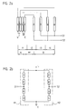
- a first position measuring device is shown schematically in a longitudinal view, in which a material measure 1 made of a magnetizable material is attached to a first object 2 in any manner.
- the material measure 1 has on one surface a periodic measuring graduation 3 with regions NS magnetized alternately with opposite poles in the measuring direction X, at the region boundaries of which two north poles NN and two south poles SS adjoin one another.
- the measuring graduation 3 has a graduation period t which is defined by the pole spacing of each area NS.
- a scanning unit 5 is connected to a second object 4, which scans the measuring graduation 3 of the material measure 1 to generate position-dependent output signals which position measurement values for the relative position of the two objects 2, 4 are formed in a downstream evaluation device.
- these strip-shaped magnetoresistive elements An, Bn of the two groups A, B extend perpendicular to the measuring direction X and are arranged parallel to one another in the measuring direction X.
- first magnetoresistive element A1 with the output signal of the phase position 0 ° at the first position "0 °”
- the second magnetoresistive element A2 with the output signal of the phase position 90 ° at the second position "90 °”
- the third magnetoresistive element A3 with the output signal of the phase position 180 ° at the third position "180 °”
- the fourth magnetoresistive element A4 with the output signal of the phase position 270 ° at the fourth position "270 °” of the first division period t1.
- the four magnetoresistive elements B1 to B4 of the second group B are arranged in the adjacent graduation periods t2, t3, t4 of the measuring graduation 3.
- the mutual distance of the magnetoresistive Elements B1 to B4 is 3t / 4.
- the Nth magnetoresistive element at one group A is directly electrically connected to the Nth magnetoresistive element Bn of the other group B, that is to say connected in series.
- the respectively connected elements An, Bn of one group An and the other group Bn have the same phase position in relation to the division.
- the element A4 with the phase angle 270 ° is connected in series with the element B4 with the phase angle 270 °, the element A3 with the phase angle 180 ° with the element B3 with the phase angle 180 °, the element A2 with the phase angle 90 ° with the Element B2 with the phase angle 90 ° and element A1 with the phase angle 0 ° with element B1 with the phase angle 0 °.
- the two groups A, B of the basic arrangement are spaced apart by the center distance M1 of a division period t.
- the scanning unit 5 with respect to the measuring graduation 3 has a first zero-symmetrical output signal S1 with the phase position 0 ° at the center tap of the first half-bridge circuit H1 and a second zero-symmetrical output signal S2 with the phase position 90 ° at the center tap of the second half-bridge circuit H2, the signal periods of the division period t of the measuring division 3 correspond.
- the phase difference of 90 ° between the two zero-symmetrical output signals S1, S2 enables discrimination of the measuring direction X.
- the two zero-symmetrical output signals S1, S2 are fed to an evaluation device (not shown) with an interpolation unit for obtaining position measurement values for the relative position of the two objects 2, 4.
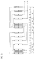
- the basic arrangement according to FIG. 2a is supplemented by a further basic arrangement according to FIG. 2a, which has a third group C each consisting of four magnetoresistive elements C1 to C4 and a fourth group D each consisting of four magnetoresistive elements D1 to D4.
- the two basic arrangements are connected in series and have a mutual center distance M2 of a division period t.
- Each element Bn of one group B is connected in series with the in-phase element Cn of the other group C. These connections can also be made without crossings by the chosen arrangement.
- a first zero-symmetrical output signal S1 with the phase position 0 ° is present at the center tap of the first half-bridge circuit H1 and a second zero-symmetrical output signal S2 with the phase position 90 ° is present at the center tap of the second half-bridge circuit H2, the signal periods of the division period t correspond to measuring graduation 3.
- the phase difference of 90 ° between the two zero-symmetrical output signals S1, S2 enables the measurement direction X to be discriminated.
- the two zero-symmetrical output signals S1, S2 are fed to an evaluation device, not shown, with an interpolation unit for obtaining position measurement values for the relative position of the two objects 2, 4.
- the magnetoresistive elements Cn, Dn of the second basic arrangement are arranged within the half bridges H3, H4, as is the arrangement of the elements An, Bn of the first basic arrangement with the half bridges H1, H2 which has already been described in detail. A further explanation is therefore unnecessary. In a manner not shown, more than two basic arrangements can also be connected in parallel.
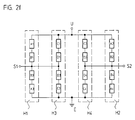
- FIGS. 2c and 2d Another advantageous possibility is to connect one or more of these series circuits in parallel to the series circuit shown in FIGS. 2c and 2d.
- the elements of this further series connection are designated A1n, B1n.
- This arrangement is shown in Figure 2g.
- the circuit for this is shown in detail in FIG. 2h. It can be seen that a further half bridge H3 is connected in parallel in order to generate the signal S1 of the first half bridge H1. Another half bridge H4 is also connected in parallel to generate the signal S2 of the second half bridge H2.
- the distance between the two series connections corresponds to a division period t.
- the magnetoresistive elements An, Bn of the basic arrangements can also be interconnected to form full bridges, as shown in FIGS. 3 described below.
- the strip-shaped magnetoresistive elements An, Bn of the two groups A, B extend perpendicular to the measuring direction X and are arranged parallel to one another in the measuring direction X.
- first magnetoresistive element A1 with the output signal of the phase position 0 ° at the first position "0 °”
- the second magnetoresistive element A2 with the output signal of the phase position 90 ° at the second position "90 °”
- the third magnetoresistive element A3 with the output signal of the phase position 180 ° at the third position "180 °”
- the fourth magnetoresistive element A4 with the output signal of the phase position 270 ° at the fourth position "270 °” of the first division period t1.
- the four magnetoresistive elements B1 to B4 of the second group B are arranged in the adjacent graduation periods t2, t3, t4 of the measuring graduation 3.
- the mutual distance between the magnetoresistive elements B1 to B4 is 3t / 4.
- the distance M1 of the last element A4 of the first group A to the first Element B2 of the second group B is t / 2.
- the element A4 with the phase angle 270 ° is thus electrically connected to the element B2 with the phase angle 90 °, the element A3 with the phase angle 180 ° with the element B1 with the phase angle 0 °, the element A2 with the phase angle 90 ° with the element B4 with the phase angle 270 ° and the element A1 with the phase angle 0 ° with the element B3 with the phase angle 180 °.
- Each element on one group A is connected to the opposite phase element Bn of the other group B.
- the selected arrangement means that the connecting lines between the elements An in one group A and the elements Bn in the other group B run without crossing.
- FIG. 3b shows in detail how the individual magnetoresistive elements An, Bn are connected together.
- the element A1 of the first group A with the phase position 0 ° forms a branch of a first half bridge
- the element B3 of the second group B with the phase position 180 ° is arranged, at the center tap signal S1b with the phase position 0 ° is present.
- a second half bridge with the elements A3, B1 is arranged parallel to this first half bridge.
- the antiphase element A3 of the same group A is arranged parallel to the element A1 and the antiphase element B1 of the same group B is arranged parallel to the element B3.
- the signals S1a and S2b which are 180 ° out of phase with one another, are tapped at the center tap.
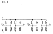
- Both half bridges form a full bridge V1, a supply voltage U being connected to elements A1, A3 and ground E being connected to elements B3, B1.
- a second full bridge V2 is arranged parallel to this first full bridge B1. It is constructed in the same way as the full bridge V1.
- One half bridge is formed by elements A2 and B4, the other half bridge by elements A4 and B2.
- the signals S2a and S2b which are phase-shifted from one another by 180 ° are tapped at the center taps.
- phase position of the elements A2, A4, B4, B2 of the second full bridge V2 differs from the phase position of the elements A1, A3, B3, B1 of the first full bridge V1 by 90 °, so that the phase position of the signals S1a, S1b also differs from that Phase position of the signals S2a, S2b differs by 90 °.
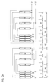
- FIGS. 3a, 3b Analogous to the already described arrangements according to FIG. 2, several basic arrangements according to FIGS. 3a, 3b can be connected together to form series connections, parallel connections or combined series-parallel connections. Such a series connection of two basic arrangements is shown in FIGS. 3c and 3d. Seen in the measuring direction X, the first group C with the elements Cn of the second basic arrangement is arranged at a distance M2 from a division period t in addition to the last element B3 of the first basic arrangement. Each element Bn of the one basic arrangement is connected in series with the in-phase element Cn of the further basic arrangement, and the elements Bn, Cn are connected to one another without crossing.
- the second group D of the second basic arrangement is next to the elements An of the first group A of the first basic arrangement at a distance M2 arranged from a division period t.
- the in-phase elements Dn, An at the two groups D, A are each connected in series and connected to one another without crossing.
- FIGS. 3a, 3b Another possibility is to connect several basic arrangements in accordance with FIGS. 3a, 3b in parallel. This arrangement is shown in Figures 3e and 3f. The two basic arrangements are arranged next to each other with a mutual distance M2 of t / 2. The same signal taps are connected to each other.
- the signals S1a, S1b and S2a, S2b are fed to a differential amplifier, at whose outputs the signals S1, phase-shifted with respect to one another, are then fed , S2 queue up.
- magnetoresistive elements can also be arranged in each group of the basic arrangements, this applies to all exemplary embodiments.
- the crossing-free connection of the magnetoresistive elements An, Bn of one group A with the other group B is essential according to the invention. This is due to the arrangements described, that is, the order selected of the elements An, Bn reached.
- the connecting lines of these elements An, Bn are laid out in such a way that starting from the center M1 of groups A, B, the connecting lines of the Nth elements An, Bn run closer to the elements An, Bn than the connecting lines of (N + 1) -th elements An, Bn, with all connecting lines running parallel to one another.
- the index n of the elements defines the phase position of the elements in relation to the measuring graduation 3.
- the index N corresponds to a sequential numbering of the successive elements, starting from a reference point.
- the invention is not limited to the length measuring device shown, it can also be used with angle measuring devices.
- the measuring graduation and possibly also the magnetoresistive elements for scanning the measuring graduation are then not linear, but are arranged on an arc or a closed circle.
- all-round scanning can also advantageously be implemented according to the invention if the basic arrangements with the magnetoresistive elements are arranged over the entire circumference.
Landscapes
- Physics & Mathematics (AREA)
- General Physics & Mathematics (AREA)
- Transmission And Conversion Of Sensor Element Output (AREA)
- Measurement Of Length, Angles, Or The Like Using Electric Or Magnetic Means (AREA)
Applications Claiming Priority (2)
| Application Number | Priority Date | Filing Date | Title |
|---|---|---|---|
| DE4316221 | 1993-05-14 | ||
| DE4316221A DE4316221C2 (de) | 1993-05-14 | 1993-05-14 | Positionsmeßeinrichtung |
Publications (2)
| Publication Number | Publication Date |
|---|---|
| EP0624778A1 true EP0624778A1 (fr) | 1994-11-17 |
| EP0624778B1 EP0624778B1 (fr) | 1998-07-01 |
Family
ID=6488129
Family Applications (1)
| Application Number | Title | Priority Date | Filing Date |
|---|---|---|---|
| EP94107106A Expired - Lifetime EP0624778B1 (fr) | 1993-05-14 | 1994-05-06 | Dispositif de mesure de position |
Country Status (4)
| Country | Link |
|---|---|
| US (1) | US5430374A (fr) |
| EP (1) | EP0624778B1 (fr) |
| JP (1) | JP2813757B2 (fr) |
| DE (2) | DE4316221C2 (fr) |
Cited By (2)
| Publication number | Priority date | Publication date | Assignee | Title |
|---|---|---|---|---|
| DE19507303A1 (de) * | 1995-03-02 | 1996-09-05 | Siemens Ag | Sensoreinrichtung mit einer Brückenschaltung von magnetoresistiven Sensorelementen |
| EP0877228A1 (fr) * | 1997-05-09 | 1998-11-11 | Brown & Sharpe Tesa S.A. | Capteur de type magnétorésistif pour mesure de dimension |
Families Citing this family (19)
| Publication number | Priority date | Publication date | Assignee | Title |
|---|---|---|---|---|
| DE4430467A1 (de) * | 1994-08-27 | 1995-10-19 | Danfoss As | Anordnung zum Messen der Lage eines beweglichen Gegenstands |
| DE4442371A1 (de) * | 1994-11-29 | 1996-05-30 | Heidenhain Gmbh Dr Johannes | Maßverkörperung |
| US6246233B1 (en) | 1994-12-30 | 2001-06-12 | Northstar Technologies Inc. | Magnetoresistive sensor with reduced output signal jitter and temperature compensation |
| WO1998016802A1 (fr) * | 1996-10-16 | 1998-04-23 | Dr. Johannes Heidenhain Gmbh | Indicateur optique de position |
| JP3004924B2 (ja) † | 1996-11-01 | 2000-01-31 | 株式会社ミツトヨ | 磁気エンコーダ |
| JP4001989B2 (ja) * | 1996-11-29 | 2007-10-31 | ドクトル・ヨハネス・ハイデンハイン・ゲゼルシヤフト・ミツト・ベシユレンクテル・ハフツング | 位置測定装置の走査部材 |
| DE19652562C2 (de) * | 1996-12-17 | 1999-07-22 | Heidenhain Gmbh Dr Johannes | Positionsmeßeinrichtung |
| US5936400A (en) * | 1996-12-23 | 1999-08-10 | Federal Products Co. | Magnetoresistive displacement sensor and variable resistor using a moving domain wall |
| DE59806597D1 (de) * | 1997-08-07 | 2003-01-23 | Heidenhain Gmbh Dr Johannes | Abtasteinheit für eine optische Positionsmesseinrichtung |
| EP0924491B1 (fr) | 1997-12-22 | 2000-08-23 | Brown & Sharpe Tesa S.A. | Circuit électronique pour dispositif de mesure de dimension à électrodes magnétorésistives |
| DE10032143C2 (de) | 1999-09-30 | 2002-07-18 | Heidenhain Gmbh Dr Johannes | Ferraris-Sensor und Verfahren zum Betrieb eines Ferraris-Sensors |
| JP2001124554A (ja) * | 1999-10-22 | 2001-05-11 | Asahi Optical Co Ltd | 磁気式エンコーダを備えた測量機 |
| JP2001124589A (ja) * | 1999-10-22 | 2001-05-11 | Asahi Optical Co Ltd | 磁気式エンコーダを搭載した測量機 |
| US6674280B1 (en) * | 1999-12-31 | 2004-01-06 | Honeywell International Inc. | Position detection apparatus with distributed bridge sensor |
| US6411081B1 (en) | 2000-02-10 | 2002-06-25 | Siemens Ag | Linear position sensor using magnetic fields |
| JP3930227B2 (ja) * | 2000-06-14 | 2007-06-13 | ペンタックス株式会社 | 磁気式エンコーダおよび磁気式エンコーダを搭載した測量機 |
| US7408343B2 (en) * | 2004-11-18 | 2008-08-05 | Honeywell International Inc. | Position detection utilizing an array of magnetic sensors with irregular spacing between sensing elements |
| US10649043B2 (en) * | 2014-04-28 | 2020-05-12 | Infineon Technologies Ag | Magnetic field sensor device configured to sense with high precision and low jitter |
| EP2955492B1 (fr) * | 2014-06-13 | 2017-05-10 | Nxp B.V. | Système de capteur avec une configuration de pont complet de quatre éléments de détection résistifs |
Citations (3)
| Publication number | Priority date | Publication date | Assignee | Title |
|---|---|---|---|---|
| GB2163852A (en) * | 1984-08-30 | 1986-03-05 | Sokkisha | Measuring apparatus using magnetoresistance elements |
| US4845456A (en) * | 1988-01-11 | 1989-07-04 | Alps Electric Co., Ltd. | Magnetic sensor |
| EP0493260A1 (fr) * | 1990-12-28 | 1992-07-01 | Sony Corporation | Capteur de position magnetorésistive |
Family Cites Families (7)
| Publication number | Priority date | Publication date | Assignee | Title |
|---|---|---|---|---|
| EP0151002B1 (fr) * | 1984-01-25 | 1991-08-28 | Matsushita Electric Industrial Co., Ltd. | Détecteur magnétique |
| JPH0820271B2 (ja) * | 1984-10-03 | 1996-03-04 | 株式会社日立製作所 | 位置や速度を検出する装置 |
| GB2191589B (en) * | 1986-06-10 | 1990-06-13 | Nippon Musical Instruments Mfg | Sensor |
| JPH02264818A (ja) * | 1989-04-05 | 1990-10-29 | Seiko Epson Corp | 磁気エンコーダー |
| JP2924236B2 (ja) * | 1991-03-20 | 1999-07-26 | ソニー・プレシジョン・テクノロジー株式会社 | 磁気センサおよび位置検出装置 |
| JP2898480B2 (ja) * | 1992-09-14 | 1999-06-02 | 日東電工株式会社 | 加熱剥離性接着剤及び粘着部材 |
| DE4233331C2 (de) * | 1992-10-05 | 1995-06-01 | Inst Mikrostrukturtechnologie | Anordnung zur Bestimmung von Positionen |
-
1993
- 1993-05-14 DE DE4316221A patent/DE4316221C2/de not_active Expired - Fee Related
-
1994
- 1994-04-26 JP JP6088830A patent/JP2813757B2/ja not_active Expired - Fee Related
- 1994-05-06 EP EP94107106A patent/EP0624778B1/fr not_active Expired - Lifetime
- 1994-05-06 US US08/239,043 patent/US5430374A/en not_active Expired - Fee Related
- 1994-05-06 DE DE59406355T patent/DE59406355D1/de not_active Expired - Fee Related
Patent Citations (3)
| Publication number | Priority date | Publication date | Assignee | Title |
|---|---|---|---|---|
| GB2163852A (en) * | 1984-08-30 | 1986-03-05 | Sokkisha | Measuring apparatus using magnetoresistance elements |
| US4845456A (en) * | 1988-01-11 | 1989-07-04 | Alps Electric Co., Ltd. | Magnetic sensor |
| EP0493260A1 (fr) * | 1990-12-28 | 1992-07-01 | Sony Corporation | Capteur de position magnetorésistive |
Cited By (4)
| Publication number | Priority date | Publication date | Assignee | Title |
|---|---|---|---|---|
| DE19507303A1 (de) * | 1995-03-02 | 1996-09-05 | Siemens Ag | Sensoreinrichtung mit einer Brückenschaltung von magnetoresistiven Sensorelementen |
| EP0877228A1 (fr) * | 1997-05-09 | 1998-11-11 | Brown & Sharpe Tesa S.A. | Capteur de type magnétorésistif pour mesure de dimension |
| US6191578B1 (en) | 1997-05-09 | 2001-02-20 | Brown & Sharpe Tesa S.A. | Magnetoresistive sensor for high precision measurements of lengths and angles |
| EP1329695A1 (fr) * | 1997-05-09 | 2003-07-23 | Tesa SA | Capteur de type magnétorésistif pour mesure de dimension |
Also Published As
| Publication number | Publication date |
|---|---|
| EP0624778B1 (fr) | 1998-07-01 |
| DE59406355D1 (de) | 1998-08-06 |
| DE4316221A1 (de) | 1994-11-17 |
| US5430374A (en) | 1995-07-04 |
| JP2813757B2 (ja) | 1998-10-22 |
| JPH0755502A (ja) | 1995-03-03 |
| DE4316221C2 (de) | 1995-11-23 |
Similar Documents
| Publication | Publication Date | Title |
|---|---|---|
| EP0624778B1 (fr) | Dispositif de mesure de position | |
| EP0554518B1 (fr) | Dispositif de mesure de position | |
| EP0121652B1 (fr) | Système pour le mesurage digital d'une longueur ou d'un angle | |
| DE69815743T2 (de) | Magnetische Codiervorrichtung mit Referenzimpuls | |
| EP0766066B1 (fr) | Dispositif magnétique pour déterminer la position ainsi que la procédure de son opération | |
| EP0620416B1 (fr) | Système de mesure magnétique | |
| DE3047809C2 (fr) | ||
| EP1462770A2 (fr) | Capteur de Hall avec décalage compensé | |
| EP0628789A1 (fr) | Dispositif de mesure de position | |
| DE19855685A1 (de) | Induktive Positionsmeßeinrichtung | |
| DE3324578A1 (de) | Vorrichtung zur kapazitiven messung einer verschiebung | |
| DE10011176C2 (de) | Zweidimensionaler Lagesensor mit magnetischem Widerstand | |
| DE1498137C3 (de) | Verfahren und Anordnung zum Interpolieren | |
| DE4422868C2 (de) | Vorrichtung zum Bestimmen eines Drehwinkels eines Magneten | |
| DE4237540A1 (de) | Verfahren zur hochauflösenden Messung von Linear- und Drehpositionen | |
| DE9321026U1 (de) | Positionsmeßeinrichtung | |
| EP0228579B1 (fr) | Tablette à digitaliser ainsi que son procédé de commande | |
| EP0784199B1 (fr) | Dispositif détecteur magnétique | |
| WO2023016691A1 (fr) | Ensemble bobine secondaire pour système codeur à induction, et système codeur à induction | |
| DE3127672A1 (de) | Einrichtung zur gleisfreilaengenmessung | |
| DE19729312A1 (de) | Absolutes magnetisches Längenmeßsystem | |
| EP0199026B1 (fr) | Table de mesure pour système de détermination de coordonnées | |
| EP0517690B1 (fr) | Système de mesure incrémentale | |
| EP0676620B1 (fr) | Système magnétique de mesure | |
| EP0384330B1 (fr) | Procédé pour la détection de la position par résolveur et synchro |
Legal Events
| Date | Code | Title | Description |
|---|---|---|---|
| PUAI | Public reference made under article 153(3) epc to a published international application that has entered the european phase |
Free format text: ORIGINAL CODE: 0009012 |
|
| 17P | Request for examination filed |
Effective date: 19940521 |
|
| AK | Designated contracting states |
Kind code of ref document: A1 Designated state(s): DE FR GB |
|
| GRAG | Despatch of communication of intention to grant |
Free format text: ORIGINAL CODE: EPIDOS AGRA |
|
| GRAG | Despatch of communication of intention to grant |
Free format text: ORIGINAL CODE: EPIDOS AGRA |
|
| GRAH | Despatch of communication of intention to grant a patent |
Free format text: ORIGINAL CODE: EPIDOS IGRA |
|
| 17Q | First examination report despatched |
Effective date: 19971119 |
|
| GRAH | Despatch of communication of intention to grant a patent |
Free format text: ORIGINAL CODE: EPIDOS IGRA |
|
| RBV | Designated contracting states (corrected) |
Designated state(s): DE FR GB |
|
| GRAA | (expected) grant |
Free format text: ORIGINAL CODE: 0009210 |
|
| AK | Designated contracting states |
Kind code of ref document: B1 Designated state(s): DE FR GB |
|
| ET | Fr: translation filed | ||
| GBT | Gb: translation of ep patent filed (gb section 77(6)(a)/1977) |
Effective date: 19980713 |
|
| REF | Corresponds to: |
Ref document number: 59406355 Country of ref document: DE Date of ref document: 19980806 |
|
| PLBE | No opposition filed within time limit |
Free format text: ORIGINAL CODE: 0009261 |
|
| STAA | Information on the status of an ep patent application or granted ep patent |
Free format text: STATUS: NO OPPOSITION FILED WITHIN TIME LIMIT |
|
| 26N | No opposition filed | ||
| REG | Reference to a national code |
Ref country code: GB Ref legal event code: IF02 |
|
| PGFP | Annual fee paid to national office [announced via postgrant information from national office to epo] |
Ref country code: FR Payment date: 20060519 Year of fee payment: 13 |
|
| PGFP | Annual fee paid to national office [announced via postgrant information from national office to epo] |
Ref country code: GB Payment date: 20060522 Year of fee payment: 13 |
|
| GBPC | Gb: european patent ceased through non-payment of renewal fee |
Effective date: 20070506 |
|
| REG | Reference to a national code |
Ref country code: FR Ref legal event code: ST Effective date: 20080131 |
|
| PG25 | Lapsed in a contracting state [announced via postgrant information from national office to epo] |
Ref country code: GB Free format text: LAPSE BECAUSE OF NON-PAYMENT OF DUE FEES Effective date: 20070506 |
|
| PG25 | Lapsed in a contracting state [announced via postgrant information from national office to epo] |
Ref country code: FR Free format text: LAPSE BECAUSE OF NON-PAYMENT OF DUE FEES Effective date: 20070531 |
|
| PGFP | Annual fee paid to national office [announced via postgrant information from national office to epo] |
Ref country code: DE Payment date: 20080523 Year of fee payment: 15 |
|
| PG25 | Lapsed in a contracting state [announced via postgrant information from national office to epo] |
Ref country code: DE Free format text: LAPSE BECAUSE OF NON-PAYMENT OF DUE FEES Effective date: 20091201 |