EP0627525A1 - Multiple section special trackwork fastener - Google Patents
Multiple section special trackwork fastener Download PDFInfo
- Publication number
- EP0627525A1 EP0627525A1 EP93304389A EP93304389A EP0627525A1 EP 0627525 A1 EP0627525 A1 EP 0627525A1 EP 93304389 A EP93304389 A EP 93304389A EP 93304389 A EP93304389 A EP 93304389A EP 0627525 A1 EP0627525 A1 EP 0627525A1
- Authority
- EP
- European Patent Office
- Prior art keywords
- top plate
- trackwork
- end portion
- load
- fastener
- Prior art date
- Legal status (The legal status is an assumption and is not a legal conclusion. Google has not performed a legal analysis and makes no representation as to the accuracy of the status listed.)
- Withdrawn
Links
- 229920001971 elastomer Polymers 0.000 claims abstract description 26
- 239000000806 elastomer Substances 0.000 claims abstract description 26
- 230000000452 restraining effect Effects 0.000 claims description 14
- 229910000831 Steel Inorganic materials 0.000 claims description 4
- 239000010959 steel Substances 0.000 claims description 4
- 244000043261 Hevea brasiliensis Species 0.000 claims description 2
- 229920006311 Urethane elastomer Polymers 0.000 claims description 2
- 239000000853 adhesive Substances 0.000 claims description 2
- 230000001070 adhesive effect Effects 0.000 claims description 2
- 229920003052 natural elastomer Polymers 0.000 claims description 2
- 229920001194 natural rubber Polymers 0.000 claims description 2
- 229920001084 poly(chloroprene) Polymers 0.000 claims description 2
- 229920003048 styrene butadiene rubber Polymers 0.000 claims description 2
- 230000001419 dependent effect Effects 0.000 claims 5
- 230000006835 compression Effects 0.000 abstract 2
- 238000007906 compression Methods 0.000 abstract 2
- 210000002105 tongue Anatomy 0.000 description 18
- 238000000034 method Methods 0.000 description 13
- 230000008569 process Effects 0.000 description 10
- 239000000463 material Substances 0.000 description 9
- 238000000465 moulding Methods 0.000 description 4
- 238000002955 isolation Methods 0.000 description 3
- 230000035939 shock Effects 0.000 description 3
- 238000001125 extrusion Methods 0.000 description 2
- 229910001204 A36 steel Inorganic materials 0.000 description 1
- 241000269350 Anura Species 0.000 description 1
- 239000004677 Nylon Substances 0.000 description 1
- 230000004075 alteration Effects 0.000 description 1
- 230000008901 benefit Effects 0.000 description 1
- 239000010960 cold rolled steel Substances 0.000 description 1
- 238000000748 compression moulding Methods 0.000 description 1
- 239000004020 conductor Substances 0.000 description 1
- 238000010276 construction Methods 0.000 description 1
- 238000010292 electrical insulation Methods 0.000 description 1
- 238000001746 injection moulding Methods 0.000 description 1
- 238000009434 installation Methods 0.000 description 1
- 238000004519 manufacturing process Methods 0.000 description 1
- 238000012986 modification Methods 0.000 description 1
- 230000004048 modification Effects 0.000 description 1
- 229920001778 nylon Polymers 0.000 description 1
- 238000001721 transfer moulding Methods 0.000 description 1
- 238000004073 vulcanization Methods 0.000 description 1
Images



Classifications
-
- E—FIXED CONSTRUCTIONS
- E01—CONSTRUCTION OF ROADS, RAILWAYS, OR BRIDGES
- E01B—PERMANENT WAY; PERMANENT-WAY TOOLS; MACHINES FOR MAKING RAILWAYS OF ALL KINDS
- E01B7/00—Switches; Crossings
- E01B7/22—Special sleepers for switches or crossings; Fastening means therefor
-
- E—FIXED CONSTRUCTIONS
- E01—CONSTRUCTION OF ROADS, RAILWAYS, OR BRIDGES
- E01B—PERMANENT WAY; PERMANENT-WAY TOOLS; MACHINES FOR MAKING RAILWAYS OF ALL KINDS
- E01B9/00—Fastening rails on sleepers, or the like
- E01B9/38—Indirect fastening of rails by using tie-plates or chairs; Fastening of rails on the tie-plates or in the chairs
- E01B9/40—Tie-plates for flat-bottom rails
- E01B9/42—Tie-plates for flat-bottom rails of two or more parts
-
- E—FIXED CONSTRUCTIONS
- E01—CONSTRUCTION OF ROADS, RAILWAYS, OR BRIDGES
- E01B—PERMANENT WAY; PERMANENT-WAY TOOLS; MACHINES FOR MAKING RAILWAYS OF ALL KINDS
- E01B9/00—Fastening rails on sleepers, or the like
- E01B9/62—Rail fastenings incorporating resilient supports
Definitions
- the invention relates to the area of trackwork fasteners for railway rails. More particularly, the invention is directed to the area of elastomeric trackwork fasteners for supporting loads, providing vibration isolation, shock attenuation, and electrical insulation for the special trackwork areas of railways such as turnouts, crossovers, crossings and switches.
- Trackwork fasteners of the resilient-type flexibly attach the railroad rail to a supporting structure such as a railroad tie or concrete abutment. Again, at turnouts, crossovers, crossings and switches, the problem arises of how to fasten the rail at these junctures.
- US patent 2,424,916 to Stedman describes one such method which uses a resilient base plate. Rapid transit systems which have a high voltage third rail further require the trackwork fastener to insulate the rail from the support structure.
- the rail is resiliently supported to provide shock attenuation and vibration isolation of the support structure.
- One such resilient trackwork fastener for the abovementioned rapid transit installations is described in US patent 3,576,293 to Landis. In all cases, a top portion of the trackwork fastener is secured to the rail by suitable means such as the spring clips described in the commonly assigned US patent 4,307,837 issued to Leingang.
- the invention provides an elastomeric assembly adapted for use with a top plate and which together comprise a special trackwork fastener for switches, turnouts, crossovers, crossings and the like which is simple, modular in construction, inexpensive to manufacture and substantially fully supports the top plate.
- the special trackwork fastener which may be modular and can be completely assembled to fit any particular special trackwork situation in the field.
- it may have a number of standard components which are mechanically interlocked.
- the present invention also provides a special trackwork fastener which has a fully supported top plate; which is easier and light to handle; in which one of the portions can be cut to size in the field; and/or in which at least one of the center portion and end portion is bonded in a variety of different lengths as standard components.
- an elastomeric assembly which is adapted for use with a top plate and together comprise a trackwork fastener which provides the abovementioned objects and which includes a first end portion, a second end portion, at least two securing elements and which may include a center portion. Further, means are provided to restrain movement of the end portions and center portion relative to the top plate.
- the trackwork fastener of the present invention that a number of standard modules or components can be assembled to fit any special trackwork requirement in the field, thus eliminating the need for specially made parts for each type of crossing, crossover, switch and turnout situation; that the number of standard modules required to be assembled to make up the trackwork assembly reduces the weight that must be moved at once by the assembler, i.e., a number of small pieces rather than one large one; and/or that the top plate of the trackwork fastener is substantially fully supported along its length.
- the invention is a trackwork fastener of the elastomeric type for attaching a railroad rail to a support structure at special trackwork areas such as turnouts, crossovers, crossings, switches and the like.
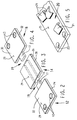
- a trackwork fastener 10 is shown which is comprised of a first end portion 12 , a center portion 14 , a second end portion 16 , securing elements 18 and top plate 20 .
- the top plate 20 includes a rail receiving surface 25 facing upward and a load bearing surface (not shown) opposing it, on the underside thereof said rail receiving surface 25 .
- the top plate 20 includes means for securing a railroad rail to the load receiving surface 25 , such as spring clip shoulders 21 or other suitable means.
- the top plate 20 is substantially fully supported along its length and is adaptable and can be modified in the field to meet the requirements of a wide variety of special trackwork applications.
- a first end portion 12 is shown, including a first end plate 22 , a first elastomer section 24 and at least one bore 13 through said first end portion 12 for accepting said securing element 18 (Fig. 1).
- the first end portion 12 includes a load receiving surface 29 on the first end plate 22 and a load reacting surface (not shown) on the opposite side, on the first elastomer section 24 . Either of these surfaces can contact the underside or load bearing surface (not shown) of the top plate 20 (Fig. 1).
- the first end plate 22 is preferably stamped from hot or cold rolled steel and is between 0.125 and 0.375 inches in thickness.
- the first elastomer section 24 is adjacent to said first end plate 22 , and preferably manufactured by bonding or molding from neoprene elastomer, natural rubber elastomer, styrene-butadiene elastomer or urethane elastomer or the like.
- neoprene elastomer natural rubber elastomer
- styrene-butadiene elastomer or urethane elastomer or the like there are two securing elements 18 through each first end portion 12 , and there needs to be at least two securing elements 18 for the trackwork fastener 10 , at least one per each of the first and second end portions 12 or 16 .
- the elastomer section 24 is preferably bonded by a suitable process, such as injection molding, transfer molding, compression molding or post vulcanization (PV) bonding to the first end plate 22 .
- PV post vulcanization
- a center portion 14 including a center plate 26 and a center elastomer section 28 .
- the center portion 14 includes a load receiving surface 29 and a load reacting surface (not shown) opposite it similar to the first end portion 12 .
- a channel 15 is formed through center elastomer section 28 to mesh with tongue 17 on first end portion 12 (Fig. 1). Together tongue 17 and channel 15 act as means 19 for restraining movement of the center portion 14 and end portions 12 and 16 relative to the top plate 20 (Fig. 1).
- the securing elements 18 are used in conjunction with the tongues 17 and channels 15 and further act as means 19 for restraining movement of said first and second end portions 12 and 16 and center portion 14 .
- the center plate 26 uses similar materials and processes as used for the first end portion 12 (Fig. 2).
- the channel 15 formed along the length of the center elastomer section 28 could also be formed by extrusion.
- a second end portion 16 is shown which is identical to first end portion 12 .
- the second end portion 16 also includes a load receiving surface 29 and a load reacting surface (not shown) opposite it, the same as first end portion 12 (Fig. 1).
- the second end plate 30 uses the same materials and processes as used for the first end portion 12 (Fig. 2).
- the securing elements 18 are accepted in the at least one bore 13 and preferably, there are two securing elements 18 (Fig. 1) inserted through the bores 13 in the second end portion 16 .
- a tongue 17 on second end portion 16 interacts with channel 15 .
- tongue 17 and channel 15 in conjunction with the securing means 18 (Fig. 1) act as means 19 for restraining movement of the center portion 14 and second end portion 16 relative to the top plate 20 (Fig. 1).
- the top plate 20 includes a rail receiving surface 25 which includes means for attaching a railroad rail on it, such as spring clip shoulders 21 .
- the spring clip shoulders 21 are preferably welded to the top plate 20 and are formed for receiving spring clips, such as Pandrol® clips, which attach the railroad rail to the rail receiving surface 25.
- Other means for attaching the railroad rail to the top plate 20 are acceptable such as bolting or clamping, as is known to those skilled in the art.
- the underside of the top plate 20 includes a load bearing surface (not shown) which supports the loads and is in contact with the first portion 12 , second portion 16 and center portion 14 , if one is used.
- a plurality of holes 23 formed through the top plate 20 receive the securing elements 18 (Fig.1). Preferably there are two holes in each end of the top plate, but only one is required. Similarly, a slot would perform the same function.
- the top plate 20 can be made to any desired length and the center portion 14 (Fig.2) can be cut or sawed to match a specified length in the field. The end portions 12 and 16 and the center portion 14 , together, will then substantially fully support the top plate 20 throughout its length. This cut to length feature makes the trackwork fastener 10 (Fig.1) easily adaptable to a wide variety of special trackwork applications.
- the top plate 20 is preferably stamped or flame cut from A36 steel and is between 0.6875 inches and 1.25 inches in thickness.
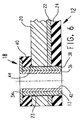
- the securing element 18 includes a washer 34 , preferably steel, a preferably steel inner member 36 including a bore 42 formed there through, a sleeve 38 of non-conducting material, preferably nylon, and an elastomer section 40 of preferably annular shape.
- the elastomer section 40 uses similar materials and processes as used for the first end portion 12 (Fig. 2). Undercut 44 allows the elastomer section 40 to be compressed without damaging the bond.
- the securing elements 18 are accepted in the at least one bore 13 in the first end portion 12 and the second end portion 16 .
- Bolting the securing element 18 through bore 42 to the supporting structure causes the load bearing surface (not shown) of the top plate 20 to contact the load receiving surface (not shown) on the first top plate 22 and slightly compress elastomer section 24 to urge the load reacting surface (not shown) into contact with the support structure.
- the sleeve 38 serves to insulate the inner member 36 from the top plate 20 and further act as a wear surface.
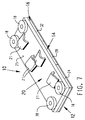
- a trackwork fastener 10 is shown which is similar to the embodiment of Fig. 1 except, the first end portion 12 , center portion 14 and second end portions 16 are flipped over such that the elastomer sections 24 , 28 , and 32 contact the top plate load bearing surface (not shown), when installed.
- first end portion 12 is shown, including a first end plate 22 , a first elastomer section 24 and at least one bore 13 there through.
- This first end portion 12 uses the same materials and processes as used for the first end portion 12 of (Fig. 2).
- the securing elements 18 act entirely as the means 19 for restraining movement relative to the top plate 20 (Fig. 7) because of the absence of the tongue 17 .
- center portion 14 including a center plate 26 and a center elastomer section 28 .
- a recess 48 is formed on one end of the center portion 14 to mesh with tongue 17 on one of end portions 12 or 16 (Fig. 10). Together tongue 17 and recess 48 act as means for restraining movement 19 of the center portion 14 and end portions 12 relative to the top plate 20 (Fig. 1) when used in conjunction with securing elements 18 (Fig. 7).
- the center portion 14 (Fig. 9) is shown for illustration purposes with a recess 48 on one end and no channel 15 or recess 48 on the other. Again, this center portion 14 uses similar materials and processes as used for the first end portion 12 in (Fig. 2).
- This embodiment further includes cored out areas 46 shown as rectangular shape and circular in shape.
- the size and shape of these cored out areas 46 can be adjusted to provide a desired spring rate per unit length.
- the spring rate per unit length for all the portions is in the range of 10,000 lb/in/in - 20,000 lb/in/in.
- the means 19 for restraining movement could be an adhesive used to secure the center portion 14 to the top plate 20 in conjunction with securing elements 18 .
- a second end portion 16 is shown.
- the second end plate 30 uses similar materials and processes as used for the first end portion 12 in (Fig. 2).
- a tongue 17 on second end portion 16 interacts with recess 48 .
- tongue 17 and recess 48 act as means 19 for restraining movement of the center portion 14 and second end portion 16 relative to the top plate 20 (Fig. 7).
- This embodiment further includes cored out areas 46 shown as having a rectangular shape.
- first end portion 12 is shown which is similar to that of the second end portion 16 of Fig. 10.
- the first end portion 12 uses similar materials and processes as the aforementioned.
- the first end portion 12 further includes a tongue 17 which extends from the elastomer section 24 and is preferably formed entirely from elastomer.
- This embodiment further includes cored out area 46 shown as circular shapes.
- FIG. 12 another embodiment of center portion 14 is shown.
- a channel 15 is formed along the length of the center portion 14 to mesh with tongue 17 on one of end portions 12 or 16 (Fig. 11 and 13).
- This embodiment further includes cored out area 46 shown in channel-type and circular shapes.
- the channel-type cored out areas 46 may be formed by extrusion, where the round cored out areas 46 would be formed by a molding operation.
- the center portion 14 uses similar materials and processes as in the aforementioned.
- a second end portion 16 is shown, which is identical to that of the first end portion 12 (Fig. 11).
- a trackwork fastener 10 is shown which is comprised of a first end portion 12 , a center portion 14 and a second end portion 16 , securing elements 18 , collectively referred to as the elastomeric assembly, and top plate 20 .
- the center portion 14 can be cut to length in the field or it can be manufactured by bonding or molding to a predetermined length.
- the center portion 14 and second end portion 16 is shown in an "as molded" condition.
- the center portion 14 , or first end portion 12 or any one thereof could be manufactured by molding and not bonded.
- first end portion 12 is shown which is identical to the embodiment in Fig. 11.
- a second end portion 16 is shown, including a second end plate 30 , a second elastomer section 32 and at least one bore 13 therethrough.
- the second end portion 16 uses similar materials and processes as in the aforementioned.
- This embodiment functions similarly to the aforementioned second end portions 16 , except it meshes with the first end portion 12 instead of a center portion 14 .
- this embodiment is a combined end portion and center portion. Again, this embodiment can be cut to length in the field. In addition, it needs no channel 15 and can be used with a first end portion 12 such as in Fig. 8.
Landscapes
- Engineering & Computer Science (AREA)
- Mechanical Engineering (AREA)
- Architecture (AREA)
- Civil Engineering (AREA)
- Structural Engineering (AREA)
- Railway Tracks (AREA)
Abstract
A special trackwork fastener (10) for supporting a railroad rail and attaching it to a support structure. The trackwork fastener (10) is modularly constructed and includes a top plate (20), resilient end portions (12) and (16), optional resilient center portion (14), and securing elements (18). The special trackwork fastener (10) has the versatility to be used in a large number of special trackwork situations such as turnouts, crossovers, crossings and switches or the like, which require a variety of lengths of trackwork fastener (10). The vertical compression stiffness and adjustability in length is provided by two opposed end portions (12),(16) and an optional center portion (14) which is molded or cut to length such that the portions collectively match the length of the top plate (20) and therefore the top plate (20) is fully supported along its length. The elastomer portions can be cored out to provide the desired compression stiffness.
Description
- The invention relates to the area of trackwork fasteners for railway rails. More particularly, the invention is directed to the area of elastomeric trackwork fasteners for supporting loads, providing vibration isolation, shock attenuation, and electrical insulation for the special trackwork areas of railways such as turnouts, crossovers, crossings and switches.
- In the olden days of railroad transportation, the rails were directly fastened to wooden railroad ties with railroad spikes. At turnouts, crossovers, crossings and switches, where there are special support and securing requirements, special fasteners were used to allow fastening of the rails to the support structure. Such special fasteners are described in US patent 1,126,530 to Liebmann.
- Trackwork fasteners of the resilient-type flexibly attach the railroad rail to a supporting structure such as a railroad tie or concrete abutment. Again, at turnouts, crossovers, crossings and switches, the problem arises of how to fasten the rail at these junctures. US patent 2,424,916 to Stedman describes one such method which uses a resilient base plate. Rapid transit systems which have a high voltage third rail further require the trackwork fastener to insulate the rail from the support structure. In addition, the rail is resiliently supported to provide shock attenuation and vibration isolation of the support structure. One such resilient trackwork fastener for the abovementioned rapid transit installations is described in US patent 3,576,293 to Landis. In all cases, a top portion of the trackwork fastener is secured to the rail by suitable means such as the spring clips described in the commonly assigned US patent 4,307,837 issued to Leingang.
- Further development in the area of resilient trackwork fasteners for turnouts, crossovers, crossings and switches led to the development of the trackwork fastener described in the commonly assigned Us patent 5,022,584 to Sherrick, which is herein incorporated by reference. Generally, a special trackwork fastener needs to be adaptable to a large number of special trackwork situations, it needs to be simple, cost effective and easily installed with as many standard components as possible. The trackwork fastener concept also needs to be such that it can be adapted and made to fit many special trackwork situations in the field.
- In light of the requirements for a special trackwork fastener the invention provides an elastomeric assembly adapted for use with a top plate and which together comprise a special trackwork fastener for switches, turnouts, crossovers, crossings and the like which is simple, modular in construction, inexpensive to manufacture and substantially fully supports the top plate.
- The special trackwork fastener which may be modular and can be completely assembled to fit any particular special trackwork situation in the field.
- Additionally or alternatively it may have a number of standard components which are mechanically interlocked.
- The present invention also provides a special trackwork fastener which has a fully supported top plate; which is easier and light to handle; in which one of the portions can be cut to size in the field; and/or in which at least one of the center portion and end portion is bonded in a variety of different lengths as standard components.
- It is a feature of at least some of the embodiments of the present invention to provide an elastomeric assembly which is adapted for use with a top plate and together comprise a trackwork fastener which provides the abovementioned objects and which includes a first end portion, a second end portion, at least two securing elements and which may include a center portion. Further, means are provided to restrain movement of the end portions and center portion relative to the top plate.
- It is an advantage of at least some embodiments of the trackwork fastener of the present invention that a number of standard modules or components can be assembled to fit any special trackwork requirement in the field, thus eliminating the need for specially made parts for each type of crossing, crossover, switch and turnout situation; that the number of standard modules required to be assembled to make up the trackwork assembly reduces the weight that must be moved at once by the assembler, i.e., a number of small pieces rather than one large one; and/or that the top plate of the trackwork fastener is substantially fully supported along its length.
- Additional inventive features will become apparent after reading the accompanying detailed descriptions.
-
- Fig.1
- is an isometric view of an embodiment of the trackwork fastener showing one method of assembly;
- Fig.2
- is an isometric view of one end portion of the trackwork fastener;
- Fig.3
- is an isometric view of the center portion of the trackwork fastener showing the channel;
- Fig.4
- is an isometric view of the other end portion of the trackwork fastener showing the tongue;
- Fig.5
- is an isometric view of a portion of the top plate of the trackwork fastener;
- Fig.6
- is an partial side sectioned view of the securing element used to fasten the top plate and end portions to the supporting structure;
- Fig.7
- is an isometric view of another method of assembly of the trackwork fastener wherein the plates are adjacent the supporting structure;
- Fig.8
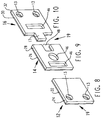
- is an isometric view of an end portion of the trackwork fastener showing without a cored out area;
- Fig.9
- is an isometric view of a center portion of the trackwork fastener showing the cored out area and the recess for accepting the tongue formed on an end portion;
- Fig. 10
- is an isometric view of an end portion of the trackwork fastener showing a cored out area and the tongue for accepting and meshing with the recess formed on the center portion;
- Fig. 11
- is an isometric view of an end portion of the trackwork fastener showing another type of cored out area and the tongue for meshing with the channel formed on the center portion;
- Fig. 12
- is an isometric view of a center portion of the trackwork fastener showing two types of cored out areas and the channel for accepting the tongue formed on an end portion;
- Fig. 13
- is an isometric view of an end portion of the trackwork fastener;
- Fig. 14
- is an isometric view of another embodiment of the trackwork fastener showing a molded end portion and center portion;
- Fig. 15
- is an isometric view of an end portion of the trackwork fastener; and
- Fig. 16
- is an isometric view of another end portion of the trackwork fastener.
- In the following, the invention will be described in detail with respect to the preferred embodiments, the attached illustrations, and drawings, wherein like elements will be designated by like reference numerals. The invention is a trackwork fastener of the elastomeric type for attaching a railroad rail to a support structure at special trackwork areas such as turnouts, crossovers, crossings, switches and the like.
- Referring now to Fig. 1, a
trackwork fastener 10 is shown which is comprised of afirst end portion 12, acenter portion 14, asecond end portion 16, securingelements 18 andtop plate 20. Thetop plate 20 includes arail receiving surface 25 facing upward and a load bearing surface (not shown) opposing it, on the underside thereof saidrail receiving surface 25. Thetop plate 20 includes means for securing a railroad rail to theload receiving surface 25, such asspring clip shoulders 21 or other suitable means. As will become apparent, in thistrackwork fastener 10, thetop plate 20 is substantially fully supported along its length and is adaptable and can be modified in the field to meet the requirements of a wide variety of special trackwork applications. - Now referring to Fig. 2, a
first end portion 12 is shown, including afirst end plate 22, afirst elastomer section 24 and at least one bore 13 through saidfirst end portion 12 for accepting said securing element 18 (Fig. 1). Thefirst end portion 12 includes aload receiving surface 29 on thefirst end plate 22 and a load reacting surface (not shown) on the opposite side, on thefirst elastomer section 24. Either of these surfaces can contact the underside or load bearing surface (not shown) of the top plate 20 (Fig. 1). Thefirst end plate 22 is preferably stamped from hot or cold rolled steel and is between 0.125 and 0.375 inches in thickness. - The
first elastomer section 24 is adjacent to saidfirst end plate 22, and preferably manufactured by bonding or molding from neoprene elastomer, natural rubber elastomer, styrene-butadiene elastomer or urethane elastomer or the like. Preferably, there are two securingelements 18 through eachfirst end portion 12, and there needs to be at least two securingelements 18 for thetrackwork fastener 10, at least one per each of the first andsecond end portions elastomer section 24 is preferably bonded by a suitable process, such as injection molding, transfer molding, compression molding or post vulcanization (PV) bonding to thefirst end plate 22. - Now referring to Fig. 3, a
center portion 14 is shown, including acenter plate 26 and acenter elastomer section 28. Thecenter portion 14 includes aload receiving surface 29 and a load reacting surface (not shown) opposite it similar to thefirst end portion 12. Achannel 15 is formed throughcenter elastomer section 28 to mesh withtongue 17 on first end portion 12 (Fig. 1). Togethertongue 17 andchannel 15 act as means 19 for restraining movement of thecenter portion 14 andend portions elements 18 are used in conjunction with thetongues 17 andchannels 15 and further act as means 19 for restraining movement of said first andsecond end portions center portion 14. Thecenter plate 26 uses similar materials and processes as used for the first end portion 12 (Fig. 2). Thechannel 15 formed along the length of thecenter elastomer section 28 could also be formed by extrusion. - Now referring to Fig. 4, a
second end portion 16 is shown which is identical tofirst end portion 12. Thesecond end portion 16 also includes aload receiving surface 29 and a load reacting surface (not shown) opposite it, the same as first end portion 12 (Fig. 1). Thesecond end plate 30 uses the same materials and processes as used for the first end portion 12 (Fig. 2). - Again, the securing elements 18 (Fig. 1) are accepted in the at least one bore 13 and preferably, there are two securing elements 18 (Fig. 1) inserted through the
bores 13 in thesecond end portion 16. Atongue 17 onsecond end portion 16 interacts withchannel 15. Togethertongue 17 andchannel 15 in conjunction with the securing means 18 (Fig. 1) act as means 19 for restraining movement of thecenter portion 14 andsecond end portion 16 relative to the top plate 20 (Fig. 1). - Referring now to Fig. 5, wherein a
top plate 20 is shown. Thetop plate 20 includes arail receiving surface 25 which includes means for attaching a railroad rail on it, such as spring clip shoulders 21. The spring clip shoulders 21 are preferably welded to thetop plate 20 and are formed for receiving spring clips, such as Pandrol® clips, which attach the railroad rail to therail receiving surface 25. Other means for attaching the railroad rail to thetop plate 20 are acceptable such as bolting or clamping, as is known to those skilled in the art. The underside of thetop plate 20 includes a load bearing surface (not shown) which supports the loads and is in contact with thefirst portion 12,second portion 16 andcenter portion 14, if one is used. - A plurality of
holes 23 formed through thetop plate 20 receive the securing elements 18 (Fig.1). Preferably there are two holes in each end of the top plate, but only one is required. Similarly, a slot would perform the same function. Thetop plate 20 can be made to any desired length and the center portion 14 (Fig.2) can be cut or sawed to match a specified length in the field. Theend portions center portion 14, together, will then substantially fully support thetop plate 20 throughout its length. This cut to length feature makes the trackwork fastener 10 (Fig.1) easily adaptable to a wide variety of special trackwork applications. Thetop plate 20 is preferably stamped or flame cut from A36 steel and is between 0.6875 inches and 1.25 inches in thickness. - Now referring to Fig. 6, a securing
element 18 is shown as it is installed. The securingelement 18 includes awasher 34, preferably steel, a preferably steelinner member 36 including abore 42 formed there through, a sleeve 38 of non-conducting material, preferably nylon, and anelastomer section 40 of preferably annular shape. Theelastomer section 40 uses similar materials and processes as used for the first end portion 12 (Fig. 2). Undercut 44 allows theelastomer section 40 to be compressed without damaging the bond. The securingelements 18 are accepted in the at least one bore 13 in thefirst end portion 12 and thesecond end portion 16. - Bolting the securing
element 18 throughbore 42 to the supporting structure causes the load bearing surface (not shown) of thetop plate 20 to contact the load receiving surface (not shown) on the firsttop plate 22 and slightly compresselastomer section 24 to urge the load reacting surface (not shown) into contact with the support structure. The sleeve 38 serves to insulate theinner member 36 from thetop plate 20 and further act as a wear surface. - Referring now to Fig. 7, a
trackwork fastener 10 is shown which is similar to the embodiment of Fig. 1 except, thefirst end portion 12,center portion 14 andsecond end portions 16 are flipped over such that theelastomer sections - In Fig. 8, another embodiment of
first end portion 12 is shown, including afirst end plate 22, afirst elastomer section 24 and at least one bore 13 there through. Thisfirst end portion 12 uses the same materials and processes as used for thefirst end portion 12 of (Fig. 2). Similarly, by using two securingelements 18 through theend portion 12, theend portion 12 is prevented from rotating relative to the top plate (Fig. 7). In essence, in this embodiment, the securingelements 18 act entirely as themeans 19 for restraining movement relative to the top plate 20 (Fig. 7) because of the absence of thetongue 17. - Now referring to Fig. 9, another embodiment of
center portion 14 is shown, including acenter plate 26 and acenter elastomer section 28. A recess 48 is formed on one end of thecenter portion 14 to mesh withtongue 17 on one ofend portions 12 or 16 (Fig. 10). Togethertongue 17 and recess 48 act as means for restrainingmovement 19 of thecenter portion 14 andend portions 12 relative to the top plate 20 (Fig. 1) when used in conjunction with securing elements 18 (Fig. 7). The center portion 14 (Fig. 9) is shown for illustration purposes with a recess 48 on one end and nochannel 15 or recess 48 on the other. Again, thiscenter portion 14 uses similar materials and processes as used for thefirst end portion 12 in (Fig. 2). - This embodiment further includes cored out
areas 46 shown as rectangular shape and circular in shape. The size and shape of these cored outareas 46 can be adjusted to provide a desired spring rate per unit length. By way of example and not by limitation, the spring rate per unit length for all the portions is in the range of 10,000 lb/in/in - 20,000 lb/in/in. Further, as shown by the left end of thecenter portion 14, no tongue or recess need be present. The means 19 for restraining movement could be an adhesive used to secure thecenter portion 14 to thetop plate 20 in conjunction with securingelements 18. - Now referring to Fig. 10, a
second end portion 16 is shown. Thesecond end plate 30 uses similar materials and processes as used for thefirst end portion 12 in (Fig. 2). Atongue 17 onsecond end portion 16 interacts with recess 48. Togethertongue 17 and recess 48 act as means 19 for restraining movement of thecenter portion 14 andsecond end portion 16 relative to the top plate 20 (Fig. 7). This embodiment further includes cored outareas 46 shown as having a rectangular shape. - Now referring to Fig. 11, another embodiment of
first end portion 12 is shown which is similar to that of thesecond end portion 16 of Fig. 10. Thefirst end portion 12 uses similar materials and processes as the aforementioned. Thefirst end portion 12 further includes atongue 17 which extends from theelastomer section 24 and is preferably formed entirely from elastomer. This embodiment further includes cored outarea 46 shown as circular shapes. - Now referring to Fig. 12, another embodiment of
center portion 14 is shown. Achannel 15 is formed along the length of thecenter portion 14 to mesh withtongue 17 on one ofend portions 12 or 16 (Fig. 11 and 13). This embodiment further includes cored outarea 46 shown in channel-type and circular shapes. The channel-type cored outareas 46 may be formed by extrusion, where the round cored outareas 46 would be formed by a molding operation. Thecenter portion 14 uses similar materials and processes as in the aforementioned. - Now referring to Fig. 13, a
second end portion 16 is shown, which is identical to that of the first end portion 12 (Fig. 11). - Referring now to Fig. 14, a
trackwork fastener 10 is shown which is comprised of afirst end portion 12, acenter portion 14 and asecond end portion 16, securingelements 18, collectively referred to as the elastomeric assembly, andtop plate 20. Thecenter portion 14 can be cut to length in the field or it can be manufactured by bonding or molding to a predetermined length. In this embodiment, thecenter portion 14 andsecond end portion 16 is shown in an "as molded" condition. Furthermore, thecenter portion 14, orfirst end portion 12 or any one thereof could be manufactured by molding and not bonded. - Now referring to Fig. 15, an embodiment of
first end portion 12 is shown which is identical to the embodiment in Fig. 11. - Finally, referring to Fig. 16, a
second end portion 16 is shown, including asecond end plate 30, asecond elastomer section 32 and at least one bore 13 therethrough. Thesecond end portion 16 uses similar materials and processes as in the aforementioned. This embodiment functions similarly to the aforementionedsecond end portions 16, except it meshes with thefirst end portion 12 instead of acenter portion 14. In essence, this embodiment is a combined end portion and center portion. Again, this embodiment can be cut to length in the field. In addition, it needs nochannel 15 and can be used with afirst end portion 12 such as in Fig. 8. - From the foregoing, it should be apparent that the present invention now provides a novel, inexpensive and very adaptable trackwork fastener for switches, turnouts, crossovers, frogs and the like which substantially fully supports the top plate along its length and provides the desired spring rate for vibration isolation and shock attenuation. While several embodiments of the present invention have been described in detail, various modifications, alterations and changes may be made without departing from the spirit and scope of the present invention defined in the appended claims.
Claims (15)
- A trackwork fastener for attaching a railroad rail to a support structure, including a top plate, means for securing said railroad rail to a rail receiving surface, a plurality of holes formed through said top plate, said top plate including a load-bearing surface opposite said rail-receiving surface, said trackwork fastener being characterized by(a) a first end portion for supporting said top plate, said first end portion including a first elastomer section and means for restraining movement relative to said top plate, said first end portion having a load-receiving surface and a load-reacting surface opposing said load-receiving surface, one of said load-reacting surfaces of said first end portion and said load-receiving surface of said first end portion contacting said load-bearing surface of said top plate;(b) a second end portion for supporting said top plate, including a second elastomer section and means for restraining movement relative to said top plate, said second end portion including a load-receiving surface and a load-reacting surface opposing said load-receiving surface, one of said load-receiving surface of said second end portion and said load-reacting surface of said second end portion contacting said load-bearing surface of said top plate, said second end portion being movable relative to said first end portion in a direction which is generally transverse to said railroad rail;(c) means for attaching said first and second end portions to said top plate;whereby said top plate is fully supported along its length.
- The trackwork fastener according to Claim 1 further characterized by a center portion for supporting said top plate including a center plate and a center elastomer section adjacent thereto, said center plate having a load-receiving surface and said center elastomer section having a load-reacting surface opposing said load-receiving surface, at least one of said center portion and said first and second end portions including means for restraining movement of said first and second end portions and said center portion relative to said top plate, said load-receiving surface of said center plate contacting said load-bearing surface of said top plate.
- A trackwork fastener according to Claim 1 or Claim 2 further characterized by said means for securing said rail including spring clip shoulders which are adapted for use with spring clips.
- A trackwork fastener according to Claim 3 further characterized by said spring clip shoulders being welded to said top plate.
- A trackwork fastener according to any of the preceding claims characterized by said first end portion and said second end portion including at least two bores in each for receiving first and second securing elements.
- A trackwork fastener according to any one of the preceding claims further characterized by said first elastomer section being made of natural rubber elastomer, neoprene elastomer, urethane elastomer or styrene-butadiene elastomer.
- A trackwork fastener according to any one of the preceding claims further characterized by said top plate being manufactured from plate steel having a thickness range between 0.6875 and 1.25 inches.
- A trackwork fastener according to any one of the preceding claims further characterized by said first plate being manufactured from plate steel having a thickness range between 0.125 and 0.375 inches.
- A trackwork fastener according to Claim 2 or any of Claims 3 to 8 when dependent on Claim 2, further characterized by said means for restraining movement of said center portion relative to said top plate including a channel and a tongue.
- A trackwork fastener according to Claim 2 or any one of Claims 3 to 8 when dependent on Claim 2, further characterized by said means for restraining movement of said center portion relative to said top plate including a tongue and a recess.
- A trackwork fastener according to Claim 2 or any of Claims 3 to 8 dependent on Claim 2, further characterized by said means for restraining movement of said center portion relative to said top plate including an adhesive securing said center portion to said top plate.
- A trackwork fastener according to any one of the preceding claims, further characterized by said means for restraining movement of said end portion relative to said top plate including two securing elements extending first through said top plate and then through said end portion.
- A trackwork fastener according to any one of the preceding claims, further characterized by said at least two securing elements including a washer, an inner member, a non-conducting sleeve and an elastomer section.
- A trackwork fastener according to Claim 2 or any one of Claims 2 to 13 dependent on Claim 2, further characterized by at least one of said center portion and said first and second end portions including a cored out area.
- A trackwork fastener according to Claim 2 or any one of Claims 2 to 14 when dependent on Claim 2, further characterized by said center portion exhibition a spring rate per unit length between the ranges of 10,000-20,000 pounds/inch/inch.
Priority Applications (3)
| Application Number | Priority Date | Filing Date | Title |
|---|---|---|---|
| US07/872,465 US5249743A (en) | 1992-04-23 | 1992-04-23 | Multiple section special trackwork fastener |
| CA002097556A CA2097556A1 (en) | 1992-04-23 | 1993-06-02 | Multiple section special trackwork fastener |
| EP93304389A EP0627525A1 (en) | 1992-04-23 | 1993-06-04 | Multiple section special trackwork fastener |
Applications Claiming Priority (3)
| Application Number | Priority Date | Filing Date | Title |
|---|---|---|---|
| US07/872,465 US5249743A (en) | 1992-04-23 | 1992-04-23 | Multiple section special trackwork fastener |
| CA002097556A CA2097556A1 (en) | 1992-04-23 | 1993-06-02 | Multiple section special trackwork fastener |
| EP93304389A EP0627525A1 (en) | 1992-04-23 | 1993-06-04 | Multiple section special trackwork fastener |
Publications (1)
| Publication Number | Publication Date |
|---|---|
| EP0627525A1 true EP0627525A1 (en) | 1994-12-07 |
Family
ID=27169454
Family Applications (1)
| Application Number | Title | Priority Date | Filing Date |
|---|---|---|---|
| EP93304389A Withdrawn EP0627525A1 (en) | 1992-04-23 | 1993-06-04 | Multiple section special trackwork fastener |
Country Status (3)
| Country | Link |
|---|---|
| US (1) | US5249743A (en) |
| EP (1) | EP0627525A1 (en) |
| CA (1) | CA2097556A1 (en) |
Cited By (4)
| Publication number | Priority date | Publication date | Assignee | Title |
|---|---|---|---|---|
| DE19919506A1 (en) * | 1999-04-29 | 2000-11-30 | Thyssen Krupp Materials & Serv | Elastic rail mounting for tracks on permanent ways has base plate supported on side contact faces of sleeper or sub base |
| EP1079023A3 (en) * | 1999-08-23 | 2001-03-07 | Tae-Woong Choi | Elastic rail pad |
| KR100383578B1 (en) * | 1999-07-21 | 2003-05-14 | 최태웅 | A apparatus for preventing vibration of railroad and subway |
| EP3290583A1 (en) * | 2016-09-02 | 2018-03-07 | Duro Felguera Rail, S.A.U. | Modular rail fastening system |
Families Citing this family (10)
| Publication number | Priority date | Publication date | Assignee | Title |
|---|---|---|---|---|
| US5485955A (en) * | 1994-07-11 | 1996-01-23 | Kerr-Mcgee Chemical Corporation | Rail-tie fastening assembly for concrete tie |
| US5551632A (en) * | 1994-11-02 | 1996-09-03 | Illinois Tool Works Inc. | Elastomeric pad between railroad rail and railroad tie |
| US5551633A (en) * | 1994-11-02 | 1996-09-03 | Illinois Tool Works, Inc. | Elastomeric pad between railroad rail and railroad tie |
| US5549245A (en) * | 1994-11-02 | 1996-08-27 | Illinois Tool Works Inc. | Composite pad useful between railroad rail and railroad tie |
| DE102013104907A1 (en) * | 2013-05-13 | 2014-11-13 | Vossloh-Werke Gmbh | System for securing rails intended for rail vehicles, fastening point for rails, device for laying rails and shim |
| US9815947B2 (en) * | 2015-10-30 | 2017-11-14 | E I Du Pont De Nemours And Company | Substantially symmetrical 3-arm star block copolymers |
| HUE044057T2 (en) * | 2016-04-22 | 2019-09-30 | Schwihag Ag | Device for fixing a rail for rail vehicles |
| US10240299B2 (en) * | 2016-07-25 | 2019-03-26 | Progress Rail Services Corporation | Mechanism and system for fastening track rail to a substrate and track rail fastening method |
| DE102018117453A1 (en) * | 2018-07-19 | 2020-01-23 | Schwihag Ag Gleis- Und Weichentechnik | Rail fastening system |
| DE202018106074U1 (en) | 2018-10-24 | 2018-11-07 | Voestalpine Bwg Gmbh | Support for a rail |
Citations (7)
| Publication number | Priority date | Publication date | Assignee | Title |
|---|---|---|---|---|
| US1729134A (en) * | 1928-02-20 | 1929-09-24 | Andrew J Shurtz | Adjustable tie plate and rail clamp |
| US1745763A (en) * | 1929-02-09 | 1930-02-04 | Iida Masanao | Rail plate |
| GB529961A (en) * | 1939-06-13 | 1940-12-02 | Taylor Bros Sandiacre Ltd | Improvements in or relating to railway and like switches |
| US2424916A (en) * | 1943-08-26 | 1947-07-29 | Firestone Tire & Rubber Co | Base plate for frogs and crossings |
| US3576293A (en) * | 1969-02-26 | 1971-04-27 | Landis Sales Co | Direct fixation rail fastener apparatus |
| US3858804A (en) * | 1972-08-28 | 1975-01-07 | Hixson R M | Rail fastening assembly |
| US4307837A (en) * | 1980-06-13 | 1981-12-29 | Lord Corporation | Adjustable spring clip |
Family Cites Families (11)
| Publication number | Priority date | Publication date | Assignee | Title |
|---|---|---|---|---|
| US1126530A (en) * | 1913-08-27 | 1915-01-26 | Vignoles Rail Chair Company | Chair for frog and switch guard-rails. |
| US1550584A (en) * | 1924-06-20 | 1925-08-18 | John G Snyder | Tie and fastener |
| GB922658A (en) * | 1960-11-22 | 1963-04-03 | Burns Ltd J | Electrical insulators for railway tracks |
| GB1327814A (en) * | 1970-02-20 | 1973-08-22 | Molyneux G | Anchorages for track rails |
| US3784097A (en) * | 1972-10-13 | 1974-01-08 | Landis Sales Co | Direct fixation rail fastener |
| GB1472947A (en) * | 1974-07-13 | 1977-05-11 | Resilient Grip Ltd | Multi position rail fastenings |
| US4047663A (en) * | 1975-11-21 | 1977-09-13 | Clarke Reynolds | Rail plate having spring clips and lateral positioning means |
| US4325510A (en) * | 1980-06-23 | 1982-04-20 | Lord Corporation | Adjustable spring clip |
| DE3512987A1 (en) * | 1985-04-11 | 1986-10-16 | Phoenix Ag, 2100 Hamburg | ELASTIC RAIL BEARING |
| US4844338A (en) * | 1986-12-05 | 1989-07-04 | Lord Corporation | Rail fastener |
| US5022584A (en) * | 1988-12-27 | 1991-06-11 | Lord Corporation | Rail-fastening for rails |
-
1992
- 1992-04-23 US US07/872,465 patent/US5249743A/en not_active Expired - Fee Related
-
1993
- 1993-06-02 CA CA002097556A patent/CA2097556A1/en not_active Abandoned
- 1993-06-04 EP EP93304389A patent/EP0627525A1/en not_active Withdrawn
Patent Citations (7)
| Publication number | Priority date | Publication date | Assignee | Title |
|---|---|---|---|---|
| US1729134A (en) * | 1928-02-20 | 1929-09-24 | Andrew J Shurtz | Adjustable tie plate and rail clamp |
| US1745763A (en) * | 1929-02-09 | 1930-02-04 | Iida Masanao | Rail plate |
| GB529961A (en) * | 1939-06-13 | 1940-12-02 | Taylor Bros Sandiacre Ltd | Improvements in or relating to railway and like switches |
| US2424916A (en) * | 1943-08-26 | 1947-07-29 | Firestone Tire & Rubber Co | Base plate for frogs and crossings |
| US3576293A (en) * | 1969-02-26 | 1971-04-27 | Landis Sales Co | Direct fixation rail fastener apparatus |
| US3858804A (en) * | 1972-08-28 | 1975-01-07 | Hixson R M | Rail fastening assembly |
| US4307837A (en) * | 1980-06-13 | 1981-12-29 | Lord Corporation | Adjustable spring clip |
Cited By (4)
| Publication number | Priority date | Publication date | Assignee | Title |
|---|---|---|---|---|
| DE19919506A1 (en) * | 1999-04-29 | 2000-11-30 | Thyssen Krupp Materials & Serv | Elastic rail mounting for tracks on permanent ways has base plate supported on side contact faces of sleeper or sub base |
| KR100383578B1 (en) * | 1999-07-21 | 2003-05-14 | 최태웅 | A apparatus for preventing vibration of railroad and subway |
| EP1079023A3 (en) * | 1999-08-23 | 2001-03-07 | Tae-Woong Choi | Elastic rail pad |
| EP3290583A1 (en) * | 2016-09-02 | 2018-03-07 | Duro Felguera Rail, S.A.U. | Modular rail fastening system |
Also Published As
| Publication number | Publication date |
|---|---|
| CA2097556A1 (en) | 1994-12-03 |
| US5249743A (en) | 1993-10-05 |
Similar Documents
| Publication | Publication Date | Title |
|---|---|---|
| US5249743A (en) | Multiple section special trackwork fastener | |
| US3576293A (en) | Direct fixation rail fastener apparatus | |
| JP5227400B2 (en) | Rail fastening assembly parts | |
| RU2715918C1 (en) | Rail fastening system | |
| KR0144516B1 (en) | Floating Slab by Precast Plate | |
| US7261244B2 (en) | Tie plate | |
| US4561589A (en) | Rail fastening assembly | |
| HU224357B1 (en) | Track cover | |
| RU2385374C1 (en) | Anchor rail fastening and underterminal block of anchor rail fastening | |
| EP0376594B1 (en) | Rail-fastening for rails | |
| US4846401A (en) | Tie-down system for railroad grade crossing | |
| US4545527A (en) | Railroad grade crossing | |
| US4405081A (en) | Rail fastener with gauge adjustment | |
| KR100396349B1 (en) | Support for supporting rail of railway | |
| KR200373350Y1 (en) | RC(Reinforced Concrete) sleeper of wharf-type | |
| JPH04155001A (en) | Rail joining construction | |
| JP2596236Y2 (en) | Electric point mounting bracket | |
| CN111373096B (en) | Rail supporting and fastening device | |
| SU1664941A1 (en) | Device for enhancing transverse stability of track grid | |
| CA2244054A1 (en) | Rail fastener | |
| JP3137575B2 (en) | Sleeper tree | |
| RU93019604A (en) | RAIL STRETCHING | |
| CA3220113A1 (en) | Rail brace assembly | |
| SU1638234A1 (en) | Construction member | |
| DE59307894D1 (en) | FASTENING SYSTEM FOR RAILS UNDER SLEEVES OF A TRACK |
Legal Events
| Date | Code | Title | Description |
|---|---|---|---|
| PUAI | Public reference made under article 153(3) epc to a published international application that has entered the european phase |
Free format text: ORIGINAL CODE: 0009012 |
|
| AK | Designated contracting states |
Kind code of ref document: A1 Designated state(s): DE FR GB |
|
| STAA | Information on the status of an ep patent application or granted ep patent |
Free format text: STATUS: THE APPLICATION IS DEEMED TO BE WITHDRAWN |
|
| 18D | Application deemed to be withdrawn |
Effective date: 19950608 |