EP0627601A1 - Vorrichtung zur Regelung des Luftdurchflusses - Google Patents
Vorrichtung zur Regelung des Luftdurchflusses Download PDFInfo
- Publication number
- EP0627601A1 EP0627601A1 EP94303368A EP94303368A EP0627601A1 EP 0627601 A1 EP0627601 A1 EP 0627601A1 EP 94303368 A EP94303368 A EP 94303368A EP 94303368 A EP94303368 A EP 94303368A EP 0627601 A1 EP0627601 A1 EP 0627601A1
- Authority
- EP
- European Patent Office
- Prior art keywords
- spring
- vane
- airflow
- aperture
- spring means
- Prior art date
- Legal status (The legal status is an assumption and is not a legal conclusion. Google has not performed a legal analysis and makes no representation as to the accuracy of the status listed.)
- Withdrawn
Links
- 230000001105 regulatory effect Effects 0.000 title claims abstract description 15
- 230000006835 compression Effects 0.000 claims abstract description 11
- 238000007906 compression Methods 0.000 claims abstract description 11
- 230000009471 action Effects 0.000 claims abstract description 7
- 230000009021 linear effect Effects 0.000 claims abstract description 4
- 230000001276 controlling effect Effects 0.000 claims description 2
- 230000007246 mechanism Effects 0.000 description 4
- 230000008859 change Effects 0.000 description 3
- 238000006243 chemical reaction Methods 0.000 description 2
- 238000001816 cooling Methods 0.000 description 2
- 239000000463 material Substances 0.000 description 2
- 230000004048 modification Effects 0.000 description 2
- 238000012986 modification Methods 0.000 description 2
- 230000002441 reversible effect Effects 0.000 description 2
- 238000011144 upstream manufacturing Methods 0.000 description 2
- 238000007792 addition Methods 0.000 description 1
- 230000003247 decreasing effect Effects 0.000 description 1
- 230000001419 dependent effect Effects 0.000 description 1
- 230000000694 effects Effects 0.000 description 1
- 239000012634 fragment Substances 0.000 description 1
- 239000004033 plastic Substances 0.000 description 1
- 229920003023 plastic Polymers 0.000 description 1
- 230000004044 response Effects 0.000 description 1
- 230000000630 rising effect Effects 0.000 description 1
Images


Classifications
-
- G—PHYSICS
- G05—CONTROLLING; REGULATING
- G05D—SYSTEMS FOR CONTROLLING OR REGULATING NON-ELECTRIC VARIABLES
- G05D7/00—Control of flow
- G05D7/01—Control of flow without auxiliary power
- G05D7/0106—Control of flow without auxiliary power the sensing element being a flexible member, e.g. bellows, diaphragm, capsule
- G05D7/012—Control of flow without auxiliary power the sensing element being a flexible member, e.g. bellows, diaphragm, capsule the sensing element being deformable and acting as a valve
-
- F—MECHANICAL ENGINEERING; LIGHTING; HEATING; WEAPONS; BLASTING
- F24—HEATING; RANGES; VENTILATING
- F24F—AIR-CONDITIONING; AIR-HUMIDIFICATION; VENTILATION; USE OF AIR CURRENTS FOR SCREENING
- F24F11/00—Control or safety arrangements
- F24F11/70—Control systems characterised by their outputs; Constructional details thereof
- F24F11/72—Control systems characterised by their outputs; Constructional details thereof for controlling the supply of treated air, e.g. its pressure
- F24F11/74—Control systems characterised by their outputs; Constructional details thereof for controlling the supply of treated air, e.g. its pressure for controlling air flow rate or air velocity
- F24F11/75—Control systems characterised by their outputs; Constructional details thereof for controlling the supply of treated air, e.g. its pressure for controlling air flow rate or air velocity for maintaining constant air flow rate or air velocity
-
- F—MECHANICAL ENGINEERING; LIGHTING; HEATING; WEAPONS; BLASTING
- F24—HEATING; RANGES; VENTILATING
- F24F—AIR-CONDITIONING; AIR-HUMIDIFICATION; VENTILATION; USE OF AIR CURRENTS FOR SCREENING
- F24F13/00—Details common to, or for air-conditioning, air-humidification, ventilation or use of air currents for screening
- F24F13/08—Air-flow control members, e.g. louvres, grilles, flaps or guide plates
- F24F13/10—Air-flow control members, e.g. louvres, grilles, flaps or guide plates movable, e.g. dampers
- F24F13/14—Air-flow control members, e.g. louvres, grilles, flaps or guide plates movable, e.g. dampers built up of tilting members, e.g. louvre
- F24F13/15—Air-flow control members, e.g. louvres, grilles, flaps or guide plates movable, e.g. dampers built up of tilting members, e.g. louvre with parallel simultaneously tiltable lamellae
Definitions
- This invention relates to an air flow regulating device.
- a series of manually adjustable dampers could be used to give a required air flow from various air outlets.
- a window in a building can be manually adjusted so as to vary the airflow therethrough so as to compensate for exterior conditions such as wind force, wind direction,air temperature etc. Because wind conditions change continuously it is difficult, if not impossible to achieve any consistent flow manually.
- the present invention seeks to provide an airflow regulating device in which the device is sensitive to the condition of the arriving air and controls the airflow in response thereto in a relatively simple manner.
- an airflow regulating device for regulating the airflow through an opening comprising one or more vanes extending across an aperture and movable between a first position in which the airflow through the aperture is reduced to a minimum and a second position in which the airflow through the aperture is a maximum, a surface of said vane(s) being acted on by the airflow to move the vane(s) towards the first position and control means comprising non-linear compression spring means acting on the vane(s) so as to bias the vane(s) towards the second position and adjustment means for varying the action of the spring means, the non linearality of the spring means being such that spring strength increases when the compression force acting thereon increases and vice versa .
- the spring means may comprise a spirally wound spring of pyramidal exponential or parabolic shape.
- the spring means may comprise a plurality of springs of different strengths connected in series.
- the spring means comprises a spring formed from wire of varying cross sectional area.
- the spring strength of the spring means may be adjustable so as to vary the action of the vane(s) against the airflow.
- Temperature sensing means may be provided for controlling the spring strength in dependence thereon so as to increase the flow of air with increases in temperature and vice versa or to decrease the flow of air with increases of temperature and vice versa .
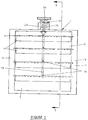
- an air flow regulating device is shown at 1 for regulating the air flow through an aperture such as an air intake into a building.
- the device 1 has an external casing 3 for location in the aperture and defining an air flow aperture 5 .
- Stretching across this aperture in a horizontal direction are a plurality of vanes 7 pivoted on rods 9 , the ends of which are located in bearings in the side walls 11 of the casing 3 .
- Each of the vanes 7 has a rigid rearwardly extending arm 15 centrally located and pivoted at the rear at 17 to a vertical connecting rod 19 so arranged that all the vanes 7 pivot together about the rods 9 .
- the movement of this connecting rod 19 is controlled by forces acting on the vanes 7 (moving the connecting rod upwards) and a control mechanism, generally indicated at 21 , (tending to move the connecting rod 19 downwards).
- control mechanism 21 is located at an angle ⁇ to the rod 19 so that it acts generally on a line connecting the ends of the arms 15 at the ends of their travel.
- the control mechanism comprises basically a spring 23 situated is a bore 25 in the upper side 27 of the casing 3 and acting, in compression, between a head 29 on the connecting rod 19 and an abutment 31 formed by a screw threaded cap 33 , screwable into the bore 25 .
- the threaded portion 35 of the cap 33 extends downwardly around the spring 23, the end position of the upper end of the spring 23 being adjusted by screwing the cap 33 in and out of the bore 25 .
- the compensating force of the spring 23 must be variable. This variation can be achieved in a number of different ways.
- Figures 4 to 7 show different spring arrangements which would be suitable for this purpose.
- Figure 4 shows a first form of spring 51 consisting of a constant dimensioned wire spring wound in a rising spiral so as to form a pyramidal shape. As the spring 51 is compressed, the spring resistance will increase to a maximum where the turns of the spring 51 are touching.
- Alternative shapes which could be used include exponential or parabolic.
- figure 5 shows a banked arrangement of three pyramidal springs 53 , 55 and 57 .
- Each of the springs 53 , 55 and 57 is formed from a different cross sectional area of wire, the spring 53 having the smallest area wire while the spring 57 has the largest area wire.
- the two upper springs 53 and 55 have their bases located on plates 59 which in turn sit on the tips of the springs 55 and 57 respectively.
- Figure 6 shows an alternative three spring arrangement with three springs 61 , 63 and 65 arranged so that the springs are connected with like ends together. This avoids the need of more than one plate 67 between the springs.
- Figure 7 shows a different approach to the single spring form.
- the spring 69 has the usual helical form, the variation in its strength being brought about by reducing the cross sectional area of the wire of which the spring 69 is wound.
- the wire is thinnest at the bottom and gradually thickens until it is at its thickest at the top.
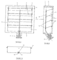
- FIGS 8 to 10 show a second form of a device in accordance with the invention.
- the rod 19 is located at the front of the vanes 7 and is pivotally connected thereto at 71 .
- each vane 7 is provided with a cut away portion 73 (see particularly figure 10), a pivot pin 75 being located across this cut away and being received in a socket arrangement 77 located on the rod 1 9.
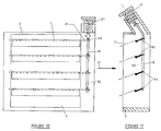
- Figures 11 and 12 show a third embodiment of the invention in which the rod 19 is located outside the aperture 5 so as to remove any obstruction to the passage of air between the vanes 7 and thus reduce the drag on the airflow.
- the pivot rods 9 at one end of the blades 7 is extended outwardly at 81 so as to pass into a chamber 83 adjacent to the aperture 5 and containing the rod 19 .
- these pivot rod extensions 81 are fixedly connected to lever arms 85 which rotate with the pivot rods 9 and thus with the vanes 7 .
- These arms 85 are pivoted to the control rod 19 at 89 .
- Figure 13 shows a modification to the embodiment shown in figures 8 to 10.
- This shows a thermal or electric actuator 91 mounted on the casing 3 by means of a mounting bracket 93 .
- the slider 97 Of the actuator 91 passes through the end cap 33 to engage the spring 23 .
- Suitable electric actuators include solenoids or motor actuators..
- Suitable thermal actuators include a thermally expanding wax device such as are often used in thermostatic regulator valves. This device would compress the spring 23 as the temperature increases, thereby increasing the air flow rate. As will be understood, this arrangement would usually be used with a cooling system and thus it would be the air flow rate of cooling air which would be controlled.
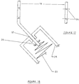
- Figure 14 shows an arrangement similar to figure 13 but arranged to decrease the air flow, for example, with increasing temperature. Thus, this arrangement could control the supply of hot air rather than cold air.
- the actuator 91 is mounted on the outside of a mounting bracket 9 4 and a reversing linkage 95 is provided to reverse the thrust provided by the actuator 91 .
- Figure 15 shows seven different configurations of vane which can be used to provide a specific characteristic of the conversion of the airflow into a force acting on the vane.
- Vane 38 is straight vane pivoted at one end.
- 40 shows a smoothly curved vane having an upwardly extending portion behind the pivot while 42 and 43 show two different aerodynamic shapes.
- 44 is a straight vane pivoted away from its ends and 46 and 48 show vanes having upwardly and downwardly extending rear portions respectively.
- Figures 16 and 17 show one example of obviating this problem.
- the rod 19 is provided with two hinge points 95 of the pin type whereby the arcuate movement of the rod 19 can be taken up to a large extent so as to provide a substantially linear action on the spring 23 .
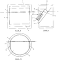
- Figures 18, 19 and 20 show embodiments in which only a single vane 7 is used.
- Figures 18 and 19 show the use of a substantially square vane 7 in a substantially square aperture 5 while figure 20 uses a circular vane 7 in a circular aperture 5 .
- the sides of the aperture 5 are squared off at 13 to avoid the vane 7 catching the circular casing 2 as the pivot axis 9 of the vane 7 is not diametral.
- Figure 19 also shows a variation of the actuating arrangement showing the use of the two pin type hinges 95 of figure 17.
- the connecting rod 19 has an upper part in the form of a connecting lever 85 which is located substantially at right angles to the rest of the rod 19 .
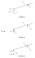
- Figures 21 to 23 show diagrammatically arrangements in which the vane shape, and therefore its effect, can be changed in dependence on the airflow.
- figure 21 shows an arrangement in which the vane 7 is provided with an extension part 101 pivoted at 103 between the positions shown in full and broken lines, the extension part 101 being biased towards its full line position by means of a light spring (not shown).
- Figure 22 is an arrangement similar to figure 21 but in this case, the extension part 101 is replaced with an extension part 105 which is produced from a flexible material such as rubber or suitable plastics material.
- Figure 23 again shows an arrangement similar to figure 21 but here an extension part 107 carries light weights 109 to give it bias.
- extension parts have been shown in connection with a flat vane 7 , they may equally well be used with any other type of vane, particularly those forms of vane shown in figure 15.
- variable strength springs which have been described could be replaced by a bank of a number of standard helical springs of different diameters and strengths. While this would produce a somewhat stepwise operation, this might well be sufficient for a number of purposes, particularly where a suitable number of individual springs were used.
- the invention provides an airflow regulating device in which the airflow can be controlled in dependence on the air pressure or air flow velocity. With suitable selection of the parameters of the control device, such control can approximate to a greater or lesser extent a constant airflow volume condition irrespective of the upstream pressure.
Landscapes
- Engineering & Computer Science (AREA)
- Physics & Mathematics (AREA)
- Fluid Mechanics (AREA)
- Chemical & Material Sciences (AREA)
- Combustion & Propulsion (AREA)
- Mechanical Engineering (AREA)
- General Engineering & Computer Science (AREA)
- General Physics & Mathematics (AREA)
- Automation & Control Theory (AREA)
- Air-Flow Control Members (AREA)
Applications Claiming Priority (6)
| Application Number | Priority Date | Filing Date | Title |
|---|---|---|---|
| GB939310150A GB9310150D0 (en) | 1993-05-15 | 1993-05-15 | This invention relates to an "airflow regulating device" |
| GB9310150 | 1993-05-15 | ||
| GB939320706A GB9320706D0 (en) | 1993-05-15 | 1993-10-07 | Air flow regulating device |
| GB9320706 | 1993-10-07 | ||
| GB9404556 | 1994-03-09 | ||
| GB9404556A GB2277987B (en) | 1993-05-15 | 1994-03-09 | Air flow regulating device |
Publications (1)
| Publication Number | Publication Date |
|---|---|
| EP0627601A1 true EP0627601A1 (de) | 1994-12-07 |
Family
ID=27266689
Family Applications (1)
| Application Number | Title | Priority Date | Filing Date |
|---|---|---|---|
| EP94303368A Withdrawn EP0627601A1 (de) | 1993-05-15 | 1994-05-11 | Vorrichtung zur Regelung des Luftdurchflusses |
Country Status (1)
| Country | Link |
|---|---|
| EP (1) | EP0627601A1 (de) |
Cited By (3)
| Publication number | Priority date | Publication date | Assignee | Title |
|---|---|---|---|---|
| GB2327121A (en) * | 1997-07-08 | 1999-01-13 | George Mclaughlin | Ventilator with an adjustable opening |
| EP0895041A3 (de) * | 1997-07-29 | 1999-10-06 | Samsung Electronics Co., Ltd. | Kühlschrank |
| EP1318358A3 (de) * | 2001-12-04 | 2005-06-08 | Emil Siegwart | Strömungsmengenregler |
Citations (4)
| Publication number | Priority date | Publication date | Assignee | Title |
|---|---|---|---|---|
| CH88609A (de) * | 1919-08-06 | 1921-03-16 | Bbc Brown Boveri & Cie | Federeinrichtung mit progressiv steigender Federkraft. |
| US3255963A (en) * | 1963-06-26 | 1966-06-14 | Boston Fluid Control Corp | Thermostatically determined constant volume fluid supply system |
| US3565105A (en) * | 1968-03-22 | 1971-02-23 | Nippon Aircon Center Co Ltd | Constant air volume device in air conditioning |
| US3955595A (en) * | 1973-11-15 | 1976-05-11 | Powers Regulator Company | Automatic fluid flow regulator |
-
1994
- 1994-05-11 EP EP94303368A patent/EP0627601A1/de not_active Withdrawn
Patent Citations (4)
| Publication number | Priority date | Publication date | Assignee | Title |
|---|---|---|---|---|
| CH88609A (de) * | 1919-08-06 | 1921-03-16 | Bbc Brown Boveri & Cie | Federeinrichtung mit progressiv steigender Federkraft. |
| US3255963A (en) * | 1963-06-26 | 1966-06-14 | Boston Fluid Control Corp | Thermostatically determined constant volume fluid supply system |
| US3565105A (en) * | 1968-03-22 | 1971-02-23 | Nippon Aircon Center Co Ltd | Constant air volume device in air conditioning |
| US3955595A (en) * | 1973-11-15 | 1976-05-11 | Powers Regulator Company | Automatic fluid flow regulator |
Cited By (4)
| Publication number | Priority date | Publication date | Assignee | Title |
|---|---|---|---|---|
| GB2327121A (en) * | 1997-07-08 | 1999-01-13 | George Mclaughlin | Ventilator with an adjustable opening |
| GB2327121B (en) * | 1997-07-08 | 2000-06-21 | George Mclaughlin | Wind operated ventilator |
| EP0895041A3 (de) * | 1997-07-29 | 1999-10-06 | Samsung Electronics Co., Ltd. | Kühlschrank |
| EP1318358A3 (de) * | 2001-12-04 | 2005-06-08 | Emil Siegwart | Strömungsmengenregler |
Similar Documents
| Publication | Publication Date | Title |
|---|---|---|
| US4147298A (en) | Fluid flow controller | |
| EP1711750B1 (de) | Mehrventildämpfer zur steuerung eines luftstroms und verfahren zur steuerung eines luftstroms | |
| US4474212A (en) | Proportional flow control valve | |
| US3976244A (en) | Adjustable air volume regulator having thermal motor actuator for effecting adjustment | |
| EP0627601A1 (de) | Vorrichtung zur Regelung des Luftdurchflusses | |
| US3495521A (en) | Manual adjustable control for air valve dampers | |
| US7296595B2 (en) | Adjustable flow rate valve | |
| US4306585A (en) | Constant flow valve | |
| US4042173A (en) | Method and apparatus for controlling volume air flow | |
| GB2277987A (en) | Air flow regulating device | |
| US3967642A (en) | Air volume regulator for air conditioning systems | |
| US3949607A (en) | Enthalpy control apparatus for air conditioning | |
| US4291832A (en) | System powered reset velocity controller | |
| US3942552A (en) | Wide range adjustable air volume regulator | |
| GB2104594A (en) | Shape memory effect i.e. engine air intake temperature control | |
| US4264035A (en) | Dual reset controller | |
| US3939868A (en) | Adjustable air volume regulator for air-conditioning systems | |
| GB2295034A (en) | Instantaneous water heater | |
| US4009826A (en) | Variable value constant volume flow device | |
| US3191615A (en) | Automatic fluid controller | |
| US4627569A (en) | Four function pneumatic controller | |
| CA1215607A (en) | Fluid flow control valves | |
| EP1026453B1 (de) | Lüftungsvorrichtung mit einem geschlitzten Rohr, die mit einem schwenkbaren Ventilelement verschliessbar ist | |
| US4467957A (en) | Flue flow regulator | |
| US4760955A (en) | Control system for heating and cooling apparatus of building |
Legal Events
| Date | Code | Title | Description |
|---|---|---|---|
| PUAI | Public reference made under article 153(3) epc to a published international application that has entered the european phase |
Free format text: ORIGINAL CODE: 0009012 |
|
| AK | Designated contracting states |
Kind code of ref document: A1 Designated state(s): BE DE DK ES FR IT NL SE |
|
| 17P | Request for examination filed |
Effective date: 19950501 |
|
| 17Q | First examination report despatched |
Effective date: 19960610 |
|
| STAA | Information on the status of an ep patent application or granted ep patent |
Free format text: STATUS: THE APPLICATION IS DEEMED TO BE WITHDRAWN |
|
| 18D | Application deemed to be withdrawn |
Effective date: 19981216 |