EP0631890B1 - Faltenbalg für den Einbau zwischen zwei gelenkig miteinander verbundene Fahrzeuge - Google Patents
Faltenbalg für den Einbau zwischen zwei gelenkig miteinander verbundene Fahrzeuge Download PDFInfo
- Publication number
- EP0631890B1 EP0631890B1 EP94110306A EP94110306A EP0631890B1 EP 0631890 B1 EP0631890 B1 EP 0631890B1 EP 94110306 A EP94110306 A EP 94110306A EP 94110306 A EP94110306 A EP 94110306A EP 0631890 B1 EP0631890 B1 EP 0631890B1
- Authority
- EP
- European Patent Office
- Prior art keywords
- bellows
- floor
- side walls
- rods
- roof
- Prior art date
- Legal status (The legal status is an assumption and is not a legal conclusion. Google has not performed a legal analysis and makes no representation as to the accuracy of the status listed.)
- Expired - Lifetime
Links
- 238000009434 installation Methods 0.000 claims abstract description 3
- 239000000463 material Substances 0.000 claims description 25
- 239000004744 fabric Substances 0.000 claims description 11
- 230000015572 biosynthetic process Effects 0.000 claims description 6
- 230000007613 environmental effect Effects 0.000 claims description 6
- 238000005755 formation reaction Methods 0.000 claims description 6
- 230000002093 peripheral effect Effects 0.000 claims 1
- 230000007306 turnover Effects 0.000 claims 1
- 230000007704 transition Effects 0.000 description 45
- 206010040954 Skin wrinkling Diseases 0.000 description 4
- 229910052751 metal Inorganic materials 0.000 description 4
- 239000002184 metal Substances 0.000 description 4
- 230000002787 reinforcement Effects 0.000 description 4
- 230000037303 wrinkles Effects 0.000 description 3
- 101100498160 Mus musculus Dach1 gene Proteins 0.000 description 2
- 238000010276 construction Methods 0.000 description 2
- 230000000694 effects Effects 0.000 description 2
- 229910000838 Al alloy Inorganic materials 0.000 description 1
- 238000005299 abrasion Methods 0.000 description 1
- 238000004026 adhesive bonding Methods 0.000 description 1
- 239000012237 artificial material Substances 0.000 description 1
- 230000002950 deficient Effects 0.000 description 1
- 230000001419 dependent effect Effects 0.000 description 1
- 238000011161 development Methods 0.000 description 1
- 230000018109 developmental process Effects 0.000 description 1
- 230000001771 impaired effect Effects 0.000 description 1
- 238000004519 manufacturing process Methods 0.000 description 1
- 239000005445 natural material Substances 0.000 description 1
- 239000002245 particle Substances 0.000 description 1
- 238000007665 sagging Methods 0.000 description 1
- 238000007789 sealing Methods 0.000 description 1
- 238000009958 sewing Methods 0.000 description 1
- 239000007787 solid Substances 0.000 description 1
- 239000004753 textile Substances 0.000 description 1
- XLYOFNOQVPJJNP-UHFFFAOYSA-N water Substances O XLYOFNOQVPJJNP-UHFFFAOYSA-N 0.000 description 1
Images


Classifications
-
- B—PERFORMING OPERATIONS; TRANSPORTING
- B60—VEHICLES IN GENERAL
- B60D—VEHICLE CONNECTIONS
- B60D5/00—Gangways for coupled vehicles, e.g. of concertina type
- B60D5/003—Bellows for interconnecting vehicle parts
-
- B—PERFORMING OPERATIONS; TRANSPORTING
- B62—LAND VEHICLES FOR TRAVELLING OTHERWISE THAN ON RAILS
- B62D—MOTOR VEHICLES; TRAILERS
- B62D47/00—Motor vehicles or trailers predominantly for carrying passengers
- B62D47/02—Motor vehicles or trailers predominantly for carrying passengers for large numbers of passengers, e.g. omnibus
- B62D47/025—Motor vehicles or trailers predominantly for carrying passengers for large numbers of passengers, e.g. omnibus articulated buses with interconnecting passageway, e.g. bellows
Definitions
- the invention relates to a bellows according to the preamble of Claim 1.
- Transitional devices between articulated Road and rail vehicles enable this to be switched of people from one vehicle to another.
- the transition device has a transition bridge.
- the transitional facility has a transitional protection on the tunnel bridge or the transition bridge encloses tubular.
- the transition facility is with both ends releasably connected to the vehicle front ends, it can also be cross-divided and both Parts can in turn be releasably connected to one another.
- bellows in the form of accordion are used used, the relative movements between two articulated vehicles coupled or connected as possible should hinder little.
- the bellows tracks between two terminal strips and it is created the zigzag shape of the whole, adopted from harmonica bellows of the bellows or it forms a bellows path between two Terminal strips a channel with a substantially semicircular cross-section; there is a bellows, but in practice is also considered a bellows.
- bellows floor A particular problem area with such bellows is the bellows floor.
- the lower transition floors settle in each half of the floor and these floor halves are in the area of the center of the vehicle with their long edges so close to each other that the bellows can be released can be closed and opened.
- This possibility to be able to open and close the bellows in this meadow, enables the open bellows when installing from above over the transition bridge and preferably also the dome between the vehicles and then to close, so that the transition area also at the Underside is protected against environmental influences. These environmental influences but now the bellows floor is special Dimensions exposed.
- the bellows wear in the area the bellows bottom is generally taken into account that the ground is no longer the continuation of the Balges in its entirety between the lower ends of the Bellows sidewalls, but their own, independently on and Removable assembly is the usual with the rest of the bellows Way two side walls and a roof releasably assigned is.
- the tunnel-shaped part of the bellows with bellows roof 2 and side walls 3, 4 extend as a unit from the lower one End of one side wall 3 or 4 over this side wall, a transition arch to the roof, the roof, a transition arch from the roof to the other side wall 4 or 3 and this other Sidewall to its lower end (Fig. 1).
- the range is from the bottom of one side wall up continuously zigzag-shaped towards the lower end of the other side wall Wrinkles formed from material webs 10, wherein two webs of material, one after the other a frame forming first outer terminal block 11 or by a first inner forming a frame Terminal block 12 held together are, that form the outer and inner bellows edges.
- the upper transition arch 13 and the lower transition arch 14 can be between two folds, those from the bottom of one side wall to the bottom End of the other side wall to the area of Transitional arch limited, one additional fold each be arranged as it is known per se and serves reduce the stiffening effect of the transition arches and to help ensure that the bellows circumference is almost the same Flexibility prevails with the already mentioned goal, relative movements between two articulated coupled To hinder vehicles as little as possible through the bellows.
- FIG. 4 A preferred bellows cross section in the area of the bellows base 5 is shown in FIG. 4. Between every two outer terminal strips designed as edge profile bars 16, designated by 11 in FIG. 3, is a web of material 17, designated 10 in Fig. 3, arranged so that a trough-shaped, approximately semicircular cross-section, where the curvature is directed towards the inside of the bellows is, i.e. the channels are open to the outside. So far also a known cross-sectional shape in the case of bellows Shape of a bellows before, which therefore need not be explained in more detail.
- a bellows floor 5 with such a cross-sectional shape is now as that remaining, tunnel-shaped bellows parts 2-4, 13, 14 as independent attachable and removable unit assigned, as it is purely schematic is shown in Fig. 5.
- the lower transition arch 14 are still part of the tunnel-shaped component 2-4, 13, 14, the bellows base 5 is between the lower transition bases 14 used and held with releasable fasteners 160.
- By overlapping lower transition arches 14 and floor 5 is indicated that the connection is designed so that no environmental influences in these areas either Get inside the bellows.
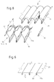
- Bellows formation of the bellows base 5 from a series of bars 170 those made of metal, e.g. an aluminum alloy or one Appropriate plastic can exist.
- the cross section these rods 170 can be oval or elliptical, such as it is shown in Fig. 6, the longer axis of the Ovals or the ellipse is vertical to provide the necessary rigidity to guarantee against sagging.
- the cross section however, the rod 170 can also be circular or the bars 170 can be suitable edge profiles. In the case an elliptical or circular cross section it is preferably hollow profiles.
- a majority of these Bars 170 are arranged parallel to one another, the rods 170 in the bellows or vehicle longitudinal direction follow each other.
- the bars 170 can be on both Ends be slotted, form end portions 18 as shown in FIG. 7 and with these slotted end sections 18 each Console 19 be plugged in, one at the bottom is firmly assigned to the first outer terminal strips 11.
- Respective Terminal strip 11 and respective bracket 19 can be welded together, glued or fixed in some other suitable way and be permanently connected.
- This detachable connection between the respective rod end 18 and the respective console 19 can by a split pin 20 or another suitable Fasteners are made.
- the bellows base 5 alone from a suitable Number of such rods 170 is formed, has the entirety of the bellows the necessary stability and if the connection between the rod ends 18 and the brackets 19 by means of the splint 20 is done in a proper manner, is the Compliance of the bellows according to the requirements not from the movements of the vehicles relative to each other impaired. If necessary, a spatial mobility be created in that the split pins 20 firmly held in the consoles 19 and the rod ends 18 around the Longitudinal axes of the split pins 20 are pivotable while the Consoles 19 so the first outer terminal strips 11 are assigned that they around a vertical axis are pivotable. It has to be the effect a rigid, rigidly connected plate should be avoided.
- the bellows stability achievable with the rods 170 is sufficient Not.
- the bars 170 must then be used as reinforcement in a bellows base assigned, the material of which in the bellows side walls and corresponds to the material used for the bellows roof, is in particular a rubberized fabric, the fabric is a preferably textile fabric in the usual way and Rubber for any impregnating natural or artificial Material stands.
- FIGS. 7 The installation of such a floor is shown in FIGS. 7 and it can be seen that despite the possibility of good Sealing around a bellows base of extremely small thickness or Height.
- Transition curve 14 is provided as an initially independent component (Fig. 1,5,7).
- Fig. 1,5,7 There are two material webs in each transition sheet 23 so many curved folds were formed, how it corresponds to the number of folds in the side walls.
- Each Material web 23 has a cross section 24 which is up to a terminal strip section 25 is sufficient, in which the respective two Material webs 23 held together along their inner edges are.
- Cut each of these terminal strips 25 begins at the bottom end of the material webs 23, runs over the cross cuts 24 of both webs of material out and ends at a distance a in front of the side wall Ends of the transition arch 14 of the pleat depth in the side walls corresponds.
- the two Material webs 23 on a length by a corresponding third Clamping strip 26 held together between the near-ground End of the distance a begins and at the cross cuts 24 ends.
- the material webs 23 form transition arches than their upper edges 27 at the cross cuts 24 run approximately horizontally like the bellows bottom to be continuous to end in sidewall-associated sections that vertical as the side walls.
- the two are still next to each other sidewall-side, free end sections of the material webs 23 in the respective fold of the respective side wall introduced by the dimension a, which corresponds to the depth of the folds, until the side walls of the terminal strips sections 25 or the third terminal strips 26 26 on one of the first inner terminal strips 12 of the respective side wall come into contact with the free side wall sections of the connecting part outside the area of the terminal strips 25 or the third terminal strips 26 26 or unfolded in the area of length a until they reach the Fasten material webs of a side wall fold and firmly these material webs are connected, for example by Gluing, sewing, vulcanizing.
- the connection can or should unsolvable between the transition part and the respective side wall be.
- the bellows base is designed as a corrugated bellows Fig. 4 is the connection of this floor with the respective bellows-shaped side wall or its lower transition arch 8, the side walls 3, 4 as in Fig. 7 shown and described are formed in Fig. 8 but only the bottom end of a lower Transition sheet 14 of a side wall is shown.
- the first inner terminal block 12 of the inner Wrinkle edges not brought up to the fold end, but ends by the dimension b before the end of the fold.
- every fold is now in the contour of the wave, it can be in the waves between each introduced two second outer terminal strips 16 of the bottom 5 and there with a Velcro fastener 27,28 placed close to the floor material and be releasably connected to it.
- the firmer, but also a detachable connection serves a first final training 29 of the respective terminal block 16 of the bumps, one corresponding second end formation 11a of the first outer terminal strips 11 and a corresponding connection profile 30 in connection with screws, rivets or the like, which by matching Holes of the two end formations 29, 11a and the connecting profile 30 and the bellows from the side wall or transition arch and floor are passed through.
- the first outer terminal strips 11 form in the roof area, in the side wall area and in the areas of the transition arch on the one hand and the second outer terminal strips 16 on the other
- Production of the detachable connection by means of the connection profiles 30 usual all-round intermediate frames of the bellows.
- the second outer terminal strips 16 define the ground clearance, these are made of abrasion-resistant material or can be and so the actual bellows material, that is coated fabric is protected from wear. Are but the second outer terminal strips 16 are actually worn, so the bellows bottom 5 can be removed in a simple manner, while side walls, The roof and transition arch remain in the installed state, the removed floor can be replaced by a replacement floor the expanded floor is not as entire assembly has become unusable; its repair is relatively easily possible because the defective become second outer terminal strips 16 and the bottom group is available for reuse.
- the second outer Terminal strips 16 functionally correspond to the bars 170 in the 7, they are "edge profiles" in the sense of Invention, the solution according to Fig. 8 represents the optimal Realization of the basic idea of the invention.
- a bellow bottom bellows main body consisting of roof, side walls and transition arch assignable interchangeably is shown in Fig. 9.
- a cloth 31 between the lower transition arches arranged to be smooth or folded like the side walls can. It's inlaid in the folds of the lower transition arch, so that there is an overlap and this state is fixed by using corresponding holes in the Fold the transition arch and into the existing one or through inserting formed folds of the floor cloth 31 a cord 32 is drawn, the ends of which are set in a suitable manner will.
Landscapes
- Engineering & Computer Science (AREA)
- Mechanical Engineering (AREA)
- Chemical & Material Sciences (AREA)
- Combustion & Propulsion (AREA)
- Transportation (AREA)
- Tents Or Canopies (AREA)
- Joints Allowing Movement (AREA)
- Diaphragms And Bellows (AREA)
- Air Bags (AREA)
- Body Structure For Vehicles (AREA)
Description
- Fig. 1
- einen als geschlossene Röhre mit zwei Seitenwänden, einem Dach, einem Boden sowie Übergangsbogen zwischen den Seitenwänden einerseits und dem Dach sowie dem Boden andererseits ausgebildeten Faltenbalg, wie er üblich ist und der Erfindung zugrundeliegt als Querschnitt;
- Fig. 2
- eine Seitenansicht eines Gelenkfahrzeuges im Bereich der einander zugekehrten Stirnseiten der gelenkig miteinander verbundenen Teilfahrzeuge, zwischen denen ein Faltenbalg eingebaut ist;
- Fig. 3
- in größerer Darstellung die Faltenkontur des Faltenbalges im Bereich des Daches, der Seitenwände und der Übergangsbogen, wie sie bei allen Ausführungsformen der Erfindung vorgesehen ist;
- Fig. 4
- in größerer Darstellung die Falten- bzw. Wellenkontur des Faltenbalges im Bereich des Balgbodens, wie sie bei einer Ausführungsform der Erfindung vorgesehen ist;
- Fig. 5
- einen Querschnitt durch einen erfindungsgemäß ausgebildeten Faltenbalg im unteren Balgbereich;
- Fig. 6
- in perspektivischer Darstellung einen erfindungsgemäßen Balgboden;
- Fig. 7
- als perspektivische Explosionsdarstellung einen erfindungsgemäßen Balg im unteren Bereich bzw. im Bereich des Übergangs zwischen einer Balgseitenwand und dem Balgboden;
- Fig. 8
- als perspektivische Explosionsdarstellung einen erfindungsgemäßen Balg in einer anderen Ausbildung im Bereich zwischen einem unteren Balgübergangsbogen und dem Balgboden und
- Fig. 9
- eine weitere erfindungsgemäße Balgausbildung.
Claims (16)
- Faltenbalg (1) für den Einbau zwischen zwei gelenkig miteinander verbundenen Fahrzeugen (6,7), der im eingebauten Zustand eine in Umfangsrichtung geschlossene, eine Übergangsbrücke umgebende Röhre mit Dach (2), Seitenwänden (3,4) und Boden (6) bildet, dadurch gekennzeichnet, daß die Röhre zweiteilig ist, deren oberes Teil (2-4) in Umfangsrichtung als Einheit aus Dach (2) und Seitenwänden (3,4) besteht und deren unteres Teil aus einer den Boden (5) bildenden selbstständig an- und ausbaubaren Baugruppe besteht, die über lösbare Befestigungsmittel im Bereich der unteren Enden der Seitenwände (3,4) mit diesen verbunden ist, sodaß nach Zuordnung der den Boden bildenden Baugruppe die in Umfangsrichtung geschlossene Röhre gebildet ist, wobei die Verbindung so ausgebildet ist, daß auch in diesen Bereichen keine Umgebungseinflüsse in das Innere des Faltenbalgs (1).
- Faltenbalg nach Anspruch 1, dessen Querschnitt im Einbauzustand die Form eines aufrechtstehenden Rechtecks mit abgerundeten Ecken hat, dadurch gekennzeichnet, daß die Seitenwände (3,4) des Balges (1) an den unteren Enden in Übergangsbögen (14) enden, mit deren den Seiten wänden (3,4) abgekehrten Enden der eine Baugruppe bildende Balgboden (5) lösbar verbunden ist.
- Faltenbalg nach Anspruch 1 oder 2, dadurch gekennzeichnet, daß der Faltenbalg (1) im Bereich des Daches (2) und der Seitenwände (3,4) gleichen Abstand zwischen inneren und äußeren Balg- bzw. Faltenkanten (11,12) hat und daß die Dicke des Faltenbalgbodens (5) wesentlich geringer ist als der Abstand zwischen inneren und äußeren Balgkanten (11,12) im Bereich von Dach (2) und Seitenwänden (3,4).
- Faltenbalg nach einem der Ansprüche 1 bis 3, dadurch gekennzeichnet, daß der Balgboden (5) die Form eines Wellenbalges (16,17) hat.
- Faltenbalg nach Anspruch 4, dadurch gekennzeichnet, daß die von der Materialbahn (17) des Wellenbalges (16,17) gebildeten Wellen des Balgbodens (5) nach innen gewölbt sind.
- Faltenbalg nach einem der Ansprüche 2 bis 5, dadurch gekennzeichnet, daß Falten des Faltenbalges vom freien Ende des einen unteren Übergangsbogens (14) über die anschließende Seitenwand (3 bzw. 4), das Dach (2) und die andere Seitenwand (4 bzw. 3) bis zum freien Ende des anderen unteren Übergangsbogens (14) durchgehend verlaufen und zwischen zwei aufeinanderfolgenden dieser Falten im Bereich der unteren Übergangsbogen (14) je eine Zwischenfalte angeordnet ist.
- Faltenbalg nach Anspruch 3, dadurch gekennzeichnet, daß der Faltenbalgboden (5) eine Mehrzahl von Stäben (170) aufweist, wobei die Stäbe 170 parallel zueinander angeordnet sind und die Stäbe (170) in Längsrichtung des Faltenbalgs (1) aufeinander folgen.
- Faltenbalg nach Anspruch 7, dadurch gekennzeichnet, daß die Stäbe (170) rotationssymmetrisch sind.
- Faltenbalg nach Anspruch 7, dadurch gekennzeichnet, daß die Querschnitte der Stäbe (170) Ellipsen bilden, deren längere Achsen hochkant stehen.
- Faltenbalg nach Anspruch 8 oder 9, dadurch gekennzeichnet, daß die Stäbe (170) Hohlprofile sind.
- Faltenbalg nach einem der Ansprüche 7 bis 9, dadurch gekennzeichnet, daß ein Tuch (21) glatt gespannt zwischen den freien Enden der unteren Übergangsbogen (14) angeordnet ist und die Stäbe (170) durch dem Tuch zugeordnete Schlaufen (22) geführt sind.
- Faltenbalg nach Anspruch 11 dadurch gekennzeichnet, daß das Tuch (21) gleichartig dem Material von Balgdach (2), Balgseitenwänden (3,4) und Übergangsbogen (13,14) ist und ein gummibeschichtetes Gewebe ist, das jedoch in sich elastich ist.
- Faltenbalg nach den Ansprüchen 4 und 5, dadurch gekennzeichnet, daß Kantprofilstäbe (16) einzelne Bahnen des Balgbodens (5) zusammenhalten, die zwischen je zwei Kantprofilstäben (16) mit etwa halbkreisförmigem Querschnitt nach oben gewölbt sind.
- Faltenbalg nach Anspruch 13 mit Kantprofilstäben (16), die vom freien Ende eines unteren Übergangsbogens (14) bis zum freien Ende des anderen unteren Übergangsbogens (14) verlaufen und Faltenbalgbahnen, Balgumkehrkanten bildend, zusammenhalten, dadurch gekennzeichnet, daß die Kantprofilstäbe (16) des Balgbodens (5) lösbar an zweite Endausbildungen (11a) der ersten äußeren Klemmleisten (11) von Dach (2) und Seitenwänden (3, 4) angeschlossen sind.
- Faltenbalg nach Anspruch 14, dadurch gekennzeichnet, daß die Balgbahnen der Balgseitenwände (3,4) bzw. deren untere Übergangsbögen (14) im Bereich der unteren Übergangsbögen (14) über die zweiten Endausbildungen (11a) hinweggeführt sind und an der Unterseite der Materialbahnen (17) des Balgbodens (5) anliegen und mit diesen dicht, aber lösbar verbunden sind.
- Faltenbalg nach Anspruch 15, dadurch gekennzeichnet, daß die dichte, aber lösbare Verbindung durch Klettbandverschlüsse erfolgt.
Applications Claiming Priority (4)
| Application Number | Priority Date | Filing Date | Title |
|---|---|---|---|
| DE4322098 | 1993-07-02 | ||
| DE19934322098 DE4322098A1 (de) | 1993-07-02 | 1993-07-02 | Übergangsschutzeinrichtung, insbesondere für Straßengelenkfahrzeuge |
| DE4341231A DE4341231A1 (de) | 1993-07-02 | 1993-12-03 | Faltenbalg zum Einbau als Übergangsschutz zwischen zwei gelenkig miteinander verbundenen Fahrzeugen |
| DE4341231 | 1993-12-03 |
Publications (2)
| Publication Number | Publication Date |
|---|---|
| EP0631890A1 EP0631890A1 (de) | 1995-01-04 |
| EP0631890B1 true EP0631890B1 (de) | 1998-04-08 |
Family
ID=25927339
Family Applications (1)
| Application Number | Title | Priority Date | Filing Date |
|---|---|---|---|
| EP94110306A Expired - Lifetime EP0631890B1 (de) | 1993-07-02 | 1994-07-02 | Faltenbalg für den Einbau zwischen zwei gelenkig miteinander verbundene Fahrzeuge |
Country Status (5)
| Country | Link |
|---|---|
| EP (1) | EP0631890B1 (de) |
| AT (1) | ATE164808T1 (de) |
| DE (2) | DE4341231A1 (de) |
| DK (1) | DK0631890T3 (de) |
| ES (1) | ES2115813T3 (de) |
Cited By (5)
| Publication number | Priority date | Publication date | Assignee | Title |
|---|---|---|---|---|
| DE10044303C1 (de) * | 2000-09-07 | 2001-10-31 | Contitech Elastomer Besch Gmbh | Durchgangsbalg für Gelenkfahrzeuge |
| DE10154033B4 (de) * | 2000-11-25 | 2006-10-19 | Hübner GmbH | Balg eines Übergangs zwischen zwei gelenkig miteinander verbundenen Fahrzeugen |
| EP1810852A1 (de) * | 2006-01-19 | 2007-07-25 | HÜBNER GmbH | Balg eines Übergangs zwischen zwei gelenkig miteinander verbundenen Fahrzeugen |
| EP2796306A1 (de) | 2013-04-25 | 2014-10-29 | Hübner GmbH & Co. KG | Übergang zwischen zwei gelenkig miteinander verbundenen Fahrzeugen |
| DE202013012585U1 (de) | 2013-04-25 | 2017-08-13 | HÜBNER GmbH & Co. KG | Übergang zwischen zwei gelenkig miteinander verbundenen Fahrzeugen |
Families Citing this family (14)
| Publication number | Priority date | Publication date | Assignee | Title |
|---|---|---|---|---|
| DE19721285A1 (de) * | 1997-05-21 | 1998-11-26 | Gebr Hennig Gmbh | Übergangsvorrichtung für zwei gelenkig miteinander verbundene Fahrzeuge |
| DE10023701A1 (de) * | 2000-05-09 | 2001-11-22 | Contitech Elastomer Besch Gmbh | Durchgangsbalg für Gelenkfahrzeuge |
| US6840529B2 (en) | 2002-10-17 | 2005-01-11 | David B. Call | Articulated pickup truck camper/trailer |
| ITBO20050031U1 (it) * | 2005-05-31 | 2006-12-01 | P E I Protezione Elaborazionei | Elemento di collegamento per profili di irrigidimento di un soffietto |
| DE102005039472B4 (de) * | 2005-08-20 | 2016-06-09 | Hübner GmbH | Fluggasttreppen- oder Fluggastbrückenabdichtung |
| ATE529276T1 (de) * | 2007-05-25 | 2011-11-15 | Hemscheidt Fahrwerktech Gmbh | Faltenbalg-anordnung für gelenkfahrzeuge sowie zugehöriger stoffboden |
| IT1390798B1 (it) * | 2008-07-31 | 2011-10-19 | Pei Protezioni Elaborazioni | Dispositivo di collegamento tra il soffietto ed il telaio di veicoli articolati. |
| ES2463866T3 (es) * | 2011-12-16 | 2014-05-29 | HÜBNER GmbH & Co. KG | Fuelle plegado o bien ondulado de unión entre dos vehículos unidos de forma articulada |
| EP2853462B1 (de) * | 2013-09-26 | 2019-02-27 | Hübner GmbH & Co. KG | Balg einer Übergangseinrichtung zwischen zwei gelenkig miteinander verbundener Fahrzeuge oder Fahrzeugteile oder Balg eines Vordachs einer Fluggastbrücke oder Fluggasttreppe |
| EP2998135B1 (de) * | 2014-09-19 | 2017-12-13 | Dellner Couplers AB | Übergang zum Verbinden eines ersten Fahrzeugteils mit einem zweiten Fahrzeugteil |
| ES2805061T3 (es) * | 2015-04-02 | 2021-02-10 | Huebner Gmbh & Co Kg | Fuelle, p. ej. de un paso entre dos vehículos unidos el uno con el otro de forma articulada |
| PL3741592T3 (pl) * | 2019-05-22 | 2022-01-31 | Ultimate Europe Transportation Equipment Gmbh | Element miecha |
| EP3798082A1 (de) | 2019-09-30 | 2021-03-31 | Dellner Couplers AB | Eckstück einer faltung eines balges einer gangway und verfahren zur herstellung solch eines eckstücks |
| EP4108538B1 (de) * | 2021-06-21 | 2024-04-03 | Dellner Couplers AB | Bälge für gangway, faltenbalg und gangway |
Family Cites Families (4)
| Publication number | Priority date | Publication date | Assignee | Title |
|---|---|---|---|---|
| US2193156A (en) * | 1939-03-17 | 1940-03-12 | Vernon F Antoine | Articulated vehicle construction |
| DE3612425A1 (de) * | 1986-04-12 | 1987-10-15 | Huebner Gummi & Kunststoff | Uebergangsschutz |
| DE3634641A1 (de) * | 1986-10-10 | 1988-04-14 | Huebner Gummi & Kunststoff | Faltenbalg |
| EP0544203B1 (de) * | 1991-11-27 | 1998-02-18 | HÜBNER GUMMI- UND KUNSTSTOFF GmbH | Faltenbalg für Gelenkfahrzeuge |
-
1993
- 1993-12-03 DE DE4341231A patent/DE4341231A1/de not_active Ceased
-
1994
- 1994-07-02 EP EP94110306A patent/EP0631890B1/de not_active Expired - Lifetime
- 1994-07-02 DK DK94110306T patent/DK0631890T3/da active
- 1994-07-02 ES ES94110306T patent/ES2115813T3/es not_active Expired - Lifetime
- 1994-07-02 AT AT94110306T patent/ATE164808T1/de active
- 1994-07-02 DE DE59405614T patent/DE59405614D1/de not_active Expired - Lifetime
Cited By (8)
| Publication number | Priority date | Publication date | Assignee | Title |
|---|---|---|---|---|
| DE10044303C1 (de) * | 2000-09-07 | 2001-10-31 | Contitech Elastomer Besch Gmbh | Durchgangsbalg für Gelenkfahrzeuge |
| DE10154033B4 (de) * | 2000-11-25 | 2006-10-19 | Hübner GmbH | Balg eines Übergangs zwischen zwei gelenkig miteinander verbundenen Fahrzeugen |
| EP1810852A1 (de) * | 2006-01-19 | 2007-07-25 | HÜBNER GmbH | Balg eines Übergangs zwischen zwei gelenkig miteinander verbundenen Fahrzeugen |
| DE102006002655A1 (de) * | 2006-01-19 | 2007-08-09 | Hübner GmbH | Balg eines Übergangs zwischen zwei gelenkig miteinander verbundenen Fahrzeugen |
| DE102006002655B4 (de) * | 2006-01-19 | 2008-03-06 | Hübner GmbH | Balg eines Übergangs zwischen zwei gelenkig miteinander verbundenen Fahrzeugen |
| US7568435B2 (en) | 2006-01-19 | 2009-08-04 | Hübner GmbH | Bellows of a connection between two hinge-linked vehicles |
| EP2796306A1 (de) | 2013-04-25 | 2014-10-29 | Hübner GmbH & Co. KG | Übergang zwischen zwei gelenkig miteinander verbundenen Fahrzeugen |
| DE202013012585U1 (de) | 2013-04-25 | 2017-08-13 | HÜBNER GmbH & Co. KG | Übergang zwischen zwei gelenkig miteinander verbundenen Fahrzeugen |
Also Published As
| Publication number | Publication date |
|---|---|
| ES2115813T3 (es) | 1998-07-01 |
| DE59405614D1 (de) | 1998-05-14 |
| DK0631890T3 (da) | 1999-01-04 |
| EP0631890A1 (de) | 1995-01-04 |
| DE4341231A1 (de) | 1995-06-08 |
| ATE164808T1 (de) | 1998-04-15 |
Similar Documents
| Publication | Publication Date | Title |
|---|---|---|
| EP0631890B1 (de) | Faltenbalg für den Einbau zwischen zwei gelenkig miteinander verbundene Fahrzeuge | |
| DE2404966C3 (de) | Endlose Gleisbandmatte fur ein Fahrzeug mit schwenkbarem Gleisband | |
| EP1741573B1 (de) | Spurfugenabdeckung bei Gelenkfahrzeugen | |
| DE3928379C2 (de) | ||
| DE9413320U1 (de) | Faltenbalg | |
| EP1391329B1 (de) | Falte oder Welle eines Balges oder Überganges zwischen zwei gelenkig miteinander verbundenen Fahrzeugen oder Fahrzeugteilen | |
| CH621303A5 (de) | ||
| EP2033827A2 (de) | Ablegbare Dachanordnung für ein Kraftfahrzeug | |
| EP2322363B1 (de) | Gelenkfahrzeug, z.B. Gelenkbus oder Schienenfahrzeug | |
| DE19821083B4 (de) | Balg eines Übergangs zwischen zwei gelenkig miteinander verbundenen Fahrzeugen oder Fahrzeugteilen | |
| DE4322098A1 (de) | Übergangsschutzeinrichtung, insbesondere für Straßengelenkfahrzeuge | |
| EP0653319B1 (de) | Faltenbalg als Übergangsschutz für Gelenkfahrzeuge | |
| DE2646663B2 (de) | Faltenbalg für Gelenkfahrzeuge | |
| EP0275365B1 (de) | Faltenbalg für Fahrzeugverbindungsdurchgänge | |
| DE4407805C2 (de) | Wagenkasten für Schienenfahrzeuge | |
| DE3613729C2 (de) | ||
| DE10005994C1 (de) | Schürzenfaltenbalg zur Abdeckung der Spurfuge eines Gelenkfahrzeuges | |
| DE102004005589B4 (de) | Aufstelldach für ein Fahrzeug, insbesondere für ein Champingfahrzeug | |
| DE3019896C2 (de) | ||
| EP0974473B1 (de) | Balg oder Element eines Balges eines Überganges zwischen zwei gelenkig miteinander verbundenen Fahrzeugen | |
| DE202018103500U1 (de) | Verbindungsorgan oder Gurtspanner für ein Verdeck auf einem Fahrzeug zur Beförderung von Lasten und Verdeck | |
| DE202022102312U1 (de) | Öffenbares Seitenplanenwandsystem | |
| EP0882612B1 (de) | Zusammenschiebbares Verdeck für Fahrzeugaufbauten u.Container | |
| DE69500750T2 (de) | Schmutzfänger | |
| DE19721285A1 (de) | Übergangsvorrichtung für zwei gelenkig miteinander verbundene Fahrzeuge |
Legal Events
| Date | Code | Title | Description |
|---|---|---|---|
| PUAI | Public reference made under article 153(3) epc to a published international application that has entered the european phase |
Free format text: ORIGINAL CODE: 0009012 |
|
| AK | Designated contracting states |
Kind code of ref document: A1 Designated state(s): AT BE CH DE DK ES FR GB GR IE IT LI LU MC NL PT SE |
|
| RBV | Designated contracting states (corrected) |
Designated state(s): AT BE CH DE DK ES FR GB GR IE IT LI NL PT SE |
|
| 17P | Request for examination filed |
Effective date: 19950616 |
|
| 17Q | First examination report despatched |
Effective date: 19960910 |
|
| GRAG | Despatch of communication of intention to grant |
Free format text: ORIGINAL CODE: EPIDOS AGRA |
|
| GRAG | Despatch of communication of intention to grant |
Free format text: ORIGINAL CODE: EPIDOS AGRA |
|
| GRAH | Despatch of communication of intention to grant a patent |
Free format text: ORIGINAL CODE: EPIDOS IGRA |
|
| GRAH | Despatch of communication of intention to grant a patent |
Free format text: ORIGINAL CODE: EPIDOS IGRA |
|
| GRAA | (expected) grant |
Free format text: ORIGINAL CODE: 0009210 |
|
| AK | Designated contracting states |
Kind code of ref document: B1 Designated state(s): AT BE CH DE DK ES FR GB GR IE IT LI NL PT SE |
|
| REF | Corresponds to: |
Ref document number: 164808 Country of ref document: AT Date of ref document: 19980415 Kind code of ref document: T |
|
| REG | Reference to a national code |
Ref country code: CH Ref legal event code: NV Representative=s name: DIPL.-ING. ETH H. R. WERFFELI PATENTANWALT Ref country code: CH Ref legal event code: EP |
|
| REF | Corresponds to: |
Ref document number: 59405614 Country of ref document: DE Date of ref document: 19980514 |
|
| GBT | Gb: translation of ep patent filed (gb section 77(6)(a)/1977) |
Effective date: 19980505 |
|
| ET | Fr: translation filed | ||
| REG | Reference to a national code |
Ref country code: ES Ref legal event code: FG2A Ref document number: 2115813 Country of ref document: ES Kind code of ref document: T3 |
|
| ITF | It: translation for a ep patent filed | ||
| REG | Reference to a national code |
Ref country code: IE Ref legal event code: FG4D Free format text: 79701 |
|
| REG | Reference to a national code |
Ref country code: PT Ref legal event code: SC4A Free format text: AVAILABILITY OF NATIONAL TRANSLATION Effective date: 19980605 |
|
| REG | Reference to a national code |
Ref country code: DK Ref legal event code: T3 |
|
| PLBE | No opposition filed within time limit |
Free format text: ORIGINAL CODE: 0009261 |
|
| STAA | Information on the status of an ep patent application or granted ep patent |
Free format text: STATUS: NO OPPOSITION FILED WITHIN TIME LIMIT |
|
| 26N | No opposition filed | ||
| REG | Reference to a national code |
Ref country code: GB Ref legal event code: IF02 |
|
| PGFP | Annual fee paid to national office [announced via postgrant information from national office to epo] |
Ref country code: CH Payment date: 20110725 Year of fee payment: 18 Ref country code: IE Payment date: 20110721 Year of fee payment: 18 Ref country code: DK Payment date: 20110720 Year of fee payment: 18 |
|
| PGFP | Annual fee paid to national office [announced via postgrant information from national office to epo] |
Ref country code: GB Payment date: 20110721 Year of fee payment: 18 Ref country code: SE Payment date: 20110722 Year of fee payment: 18 Ref country code: GR Payment date: 20110727 Year of fee payment: 18 |
|
| PGFP | Annual fee paid to national office [announced via postgrant information from national office to epo] |
Ref country code: NL Payment date: 20110726 Year of fee payment: 18 Ref country code: BE Payment date: 20110713 Year of fee payment: 18 |
|
| PGFP | Annual fee paid to national office [announced via postgrant information from national office to epo] |
Ref country code: DE Payment date: 20120711 Year of fee payment: 19 Ref country code: IT Payment date: 20120731 Year of fee payment: 19 Ref country code: ES Payment date: 20120726 Year of fee payment: 19 Ref country code: FR Payment date: 20120806 Year of fee payment: 19 |
|
| BERE | Be: lapsed |
Owner name: *HUBNER GUMMI- UND KUNSTSTOFF G.M.B.H. Effective date: 20120731 |
|
| PGFP | Annual fee paid to national office [announced via postgrant information from national office to epo] |
Ref country code: PT Payment date: 20120102 Year of fee payment: 19 |
|
| REG | Reference to a national code |
Ref country code: NL Ref legal event code: V1 Effective date: 20130201 |
|
| REG | Reference to a national code |
Ref country code: GR Ref legal event code: ML Ref document number: 980401373 Country of ref document: GR Effective date: 20130104 |
|
| REG | Reference to a national code |
Ref country code: SE Ref legal event code: EUG |
|
| GBPC | Gb: european patent ceased through non-payment of renewal fee |
Effective date: 20120702 |
|
| PGFP | Annual fee paid to national office [announced via postgrant information from national office to epo] |
Ref country code: AT Payment date: 20120711 Year of fee payment: 19 |
|
| REG | Reference to a national code |
Ref country code: DK Ref legal event code: EBP |
|
| PG25 | Lapsed in a contracting state [announced via postgrant information from national office to epo] |
Ref country code: GB Free format text: LAPSE BECAUSE OF NON-PAYMENT OF DUE FEES Effective date: 20120702 Ref country code: NL Free format text: LAPSE BECAUSE OF NON-PAYMENT OF DUE FEES Effective date: 20130201 Ref country code: SE Free format text: LAPSE BECAUSE OF NON-PAYMENT OF DUE FEES Effective date: 20120703 |
|
| REG | Reference to a national code |
Ref country code: IE Ref legal event code: MM4A |
|
| PG25 | Lapsed in a contracting state [announced via postgrant information from national office to epo] |
Ref country code: BE Free format text: LAPSE BECAUSE OF NON-PAYMENT OF DUE FEES Effective date: 20120731 Ref country code: GR Free format text: LAPSE BECAUSE OF NON-PAYMENT OF DUE FEES Effective date: 20130204 |
|
| PG25 | Lapsed in a contracting state [announced via postgrant information from national office to epo] |
Ref country code: IE Free format text: LAPSE BECAUSE OF NON-PAYMENT OF DUE FEES Effective date: 20120702 Ref country code: DK Free format text: LAPSE BECAUSE OF NON-PAYMENT OF DUE FEES Effective date: 20120731 |
|
| REG | Reference to a national code |
Ref country code: PT Ref legal event code: MM4A Free format text: LAPSE DUE TO NON-PAYMENT OF FEES Effective date: 20140102 |
|
| REG | Reference to a national code |
Ref country code: CH Ref legal event code: PL |
|
| REG | Reference to a national code |
Ref country code: AT Ref legal event code: MM01 Ref document number: 164808 Country of ref document: AT Kind code of ref document: T Effective date: 20130702 |
|
| REG | Reference to a national code |
Ref country code: FR Ref legal event code: ST Effective date: 20140331 |
|
| PG25 | Lapsed in a contracting state [announced via postgrant information from national office to epo] |
Ref country code: CH Free format text: LAPSE BECAUSE OF NON-PAYMENT OF DUE FEES Effective date: 20130731 Ref country code: LI Free format text: LAPSE BECAUSE OF NON-PAYMENT OF DUE FEES Effective date: 20130731 Ref country code: DE Free format text: LAPSE BECAUSE OF NON-PAYMENT OF DUE FEES Effective date: 20140201 |
|
| REG | Reference to a national code |
Ref country code: DE Ref legal event code: R119 Ref document number: 59405614 Country of ref document: DE Effective date: 20140201 |
|
| PG25 | Lapsed in a contracting state [announced via postgrant information from national office to epo] |
Ref country code: FR Free format text: LAPSE BECAUSE OF NON-PAYMENT OF DUE FEES Effective date: 20130731 Ref country code: IT Free format text: LAPSE BECAUSE OF NON-PAYMENT OF DUE FEES Effective date: 20130702 Ref country code: AT Free format text: LAPSE BECAUSE OF NON-PAYMENT OF DUE FEES Effective date: 20130702 |
|
| PG25 | Lapsed in a contracting state [announced via postgrant information from national office to epo] |
Ref country code: PT Free format text: LAPSE BECAUSE OF NON-PAYMENT OF DUE FEES Effective date: 20140102 |
|
| REG | Reference to a national code |
Ref country code: PT Ref legal event code: MM4A Free format text: MAXIMUM VALIDITY LIMIT REACHED Effective date: 20140702 |
|
| REG | Reference to a national code |
Ref country code: ES Ref legal event code: FD2A Effective date: 20140908 |
|
| PG25 | Lapsed in a contracting state [announced via postgrant information from national office to epo] |
Ref country code: ES Free format text: LAPSE BECAUSE OF NON-PAYMENT OF DUE FEES Effective date: 20130703 |
|
| PG25 | Lapsed in a contracting state [announced via postgrant information from national office to epo] |
Ref country code: PT Free format text: LAPSE BECAUSE OF EXPIRATION OF PROTECTION Effective date: 20140710 |
|
| PG25 | Lapsed in a contracting state [announced via postgrant information from national office to epo] |
Ref country code: PT Free format text: LAPSE BECAUSE OF EXPIRATION OF PROTECTION Effective date: 20140109 |