EP0635321A1 - Outil de poinçonnage à faible bruit - Google Patents
Outil de poinçonnage à faible bruit Download PDFInfo
- Publication number
- EP0635321A1 EP0635321A1 EP93401855A EP93401855A EP0635321A1 EP 0635321 A1 EP0635321 A1 EP 0635321A1 EP 93401855 A EP93401855 A EP 93401855A EP 93401855 A EP93401855 A EP 93401855A EP 0635321 A1 EP0635321 A1 EP 0635321A1
- Authority
- EP
- European Patent Office
- Prior art keywords
- punch
- low noise
- tool
- guide
- punch tool
- Prior art date
- Legal status (The legal status is an assumption and is not a legal conclusion. Google has not performed a legal analysis and makes no representation as to the accuracy of the status listed.)
- Granted
Links
- JOYRKODLDBILNP-UHFFFAOYSA-N Ethyl urethane Chemical compound CCOC(N)=O JOYRKODLDBILNP-UHFFFAOYSA-N 0.000 claims abstract description 24
- 238000010008 shearing Methods 0.000 claims abstract description 9
- 238000004080 punching Methods 0.000 abstract description 10
- 230000000694 effects Effects 0.000 description 3
- 238000010586 diagram Methods 0.000 description 2
- 150000003673 urethanes Chemical class 0.000 description 2
Images


Classifications
-
- B—PERFORMING OPERATIONS; TRANSPORTING
- B21—MECHANICAL METAL-WORKING WITHOUT ESSENTIALLY REMOVING MATERIAL; PUNCHING METAL
- B21D—WORKING OR PROCESSING OF SHEET METAL OR METAL TUBES, RODS OR PROFILES WITHOUT ESSENTIALLY REMOVING MATERIAL; PUNCHING METAL
- B21D28/00—Shaping by press-cutting; Perforating
- B21D28/02—Punching blanks or articles with or without obtaining scrap; Notching
- B21D28/12—Punching using rotatable carriers
-
- B—PERFORMING OPERATIONS; TRANSPORTING
- B21—MECHANICAL METAL-WORKING WITHOUT ESSENTIALLY REMOVING MATERIAL; PUNCHING METAL
- B21D—WORKING OR PROCESSING OF SHEET METAL OR METAL TUBES, RODS OR PROFILES WITHOUT ESSENTIALLY REMOVING MATERIAL; PUNCHING METAL
- B21D28/00—Shaping by press-cutting; Perforating
- B21D28/24—Perforating, i.e. punching holes
- B21D28/34—Perforating tools; Die holders
-
- Y—GENERAL TAGGING OF NEW TECHNOLOGICAL DEVELOPMENTS; GENERAL TAGGING OF CROSS-SECTIONAL TECHNOLOGIES SPANNING OVER SEVERAL SECTIONS OF THE IPC; TECHNICAL SUBJECTS COVERED BY FORMER USPC CROSS-REFERENCE ART COLLECTIONS [XRACs] AND DIGESTS
- Y10—TECHNICAL SUBJECTS COVERED BY FORMER USPC
- Y10T—TECHNICAL SUBJECTS COVERED BY FORMER US CLASSIFICATION
- Y10T83/00—Cutting
- Y10T83/202—With product handling means
- Y10T83/2092—Means to move, guide, or permit free fall or flight of product
- Y10T83/2096—Means to move product out of contact with tool
- Y10T83/2135—Moving stripper timed with tool stroke
- Y10T83/215—Carried by moving tool element or its support
- Y10T83/2155—Stripper biased against product
- Y10T83/2157—Elastomeric stripper contacting product
-
- Y—GENERAL TAGGING OF NEW TECHNOLOGICAL DEVELOPMENTS; GENERAL TAGGING OF CROSS-SECTIONAL TECHNOLOGIES SPANNING OVER SEVERAL SECTIONS OF THE IPC; TECHNICAL SUBJECTS COVERED BY FORMER USPC CROSS-REFERENCE ART COLLECTIONS [XRACs] AND DIGESTS
- Y10—TECHNICAL SUBJECTS COVERED BY FORMER USPC
- Y10T—TECHNICAL SUBJECTS COVERED BY FORMER US CLASSIFICATION
- Y10T83/00—Cutting
- Y10T83/929—Tool or tool with support
- Y10T83/9411—Cutting couple type
- Y10T83/9423—Punching tool
Definitions
- the present invention relates to a punch tool adapted to be mounted on a turret punch press, and in particular to a low noise punch tool which generates a low noise when punching a workpiece.
- a punch tool has been formed with a shearing angle in order to reduce punching noise generated when a workpiece is punched out by a turret punch press, for example.
- the present invention provides a low noise punch tool (17) which comprises a punch body (39,41), a punch guide (43) for guiding said punch body (39,41), a punch head (37) mounted on said punch body (39,41) and struck by a striker (25) of a punch press, an upper surface pad (51) formed of a low noise material and disposed on an upper surface of said punch head (37), an elastic member (55) formed of a low noise material and interposed between said punch head (37) and said punch guide (43), a stripper plate (45) provided at the lower end of said punch guide (43), and a lower surface pad (63) formed of a low noise material and attached to a lower surface of said stripper plate (45).
- the low noise punch tool further includes a ring (53) formed of a low noise material and interposed between the punch body (39,41) and the punch guide (43).
- the low noise material is preferably urethane.
- the upper surface pad (51) and the lower surface pad (63) includes a plurality of cusp push members (65) arranged circularly at regular angular intervals on the upper surface of the punch head (37) and on the lower surface of the stripper plate (45), respectively.
- Fig. 5 is a front view showing a turret punch press on which the low noise punch tool according to the present invention is mounted.
- the turret punch press 1 is composed of a lower frame 3, a pair of columns 7 disposed on both sides of the lower frame 3 to provide a working area 5, and an upper frame 9 formed integral with the pair of columns 7.
- a processing section 11 for punching a workpiece W, for instance, is provided on the left side of the working area 5.
- the processing section 11 is composed of an upper disk-shaped turret 13 rotatably mounted on the upper frame 9 and a lower disk-shaped turret 15 rotatably mounted on the lower frame 3 an appropriate distance away from the upper turret 13 in opposite positional relationship with respect to the upper turret 13.
- a plurality of upper punch tools 17 are removably arranged circularly at regular angular intervals.
- a plurality of lower die tools 19 are removably arranged circularly on the lower turret 15 so as to face the corresponding upper punch tools 17, respectively.
- Both the upper and lower turrets 13 and 15 are rotated by a turret driving mechanism (not shown) in the same direction in synchronism with each other for indexing operation. Further, the indexed upper punch tool 17 is struck against the indexed lower die tool 19 with a striker 25, which is movable up and down by a ram actuating means 23 mounted on the upper frame 9.
- a fixed table (not shown) for supporting a workpiece W is provided on the lower frame 3.
- a pair of movable tables 29 also for supporting the workpiece W are provided.
- the movable tables 29 are movable in the Y-axis (the right and left) direction.
- a carriage base 31 extending in the directions that are perpendicular to the sheet of the drawing in Fig. 5 is attached to the movable tables 29.
- a carriage 33 is mounted on the carriage base 31 so as to be movable along the carriage base 31. Further, a work clamp 35 is mounted on the carriage 33 for clamping the workpiece W.
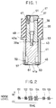
- Fig. 1 shows an embodiment of the low noise punch tool 17 according to the present invention.
- the punch tool 17 is to be attached to the turret punch press as shown in Fig. 5.
- the low noise punch tool 17 is composed of a punch head 37, a punch driver 39, a punch means 41 formed with a slanted cutting edge 41a, a punch guide 43, and a stripper plate 45, said punch driver 39 and said punch means 41 forming together a punch body.
- the punch head 37 is fixed to the top end of the punch driver 39 with a plurality of fixing screws 47. Further, an upper surface pad 51 formed of a low noise material (e.g., urethane) is bonded or baked onto the upper surface of the punch head 37. This urethane material serves to reduce noise generated when the punch punch tool 17 is struck by the striker 25 (Fig. 5).
- a low noise material e.g., urethane
- the lower end of the punch driver 39 is fixed to the upper end of the punch means 41 with a fixing screw 49.
- the cylindrical punch guide 43 is fitted to the outer circumferential surfaces of the punch driver 39 and the punch means 41 to guide the sliding movement of the punch driver 39 and the punch means 41 together in the vertical direction.
- a ring 53 formed of a low noise material e.g., urethane
- a low noise material e.g. urethane
- the stripper plate 45 is held by a plurality of plate push members 57 and a plurality of push screws 59.fixed onto said punch guide 43.
- a slanted cutting edge (knife-edge) 41a is formed with a shearing angle onto the lower end of the punch means 41 and is adapted to pass through an opening 61 of the stripper plate 45 so as to project downward from the stripper plate 45 and perform punch processing.
- a lower surface pad 63 formed of a low noise material e.g., urethane
- This urethane material serves to reduce noise generated when the stripper plate 45 is brought into contact with the workpiece W to be processed.
- Fig. 2 is a schematic diagram showing the levels of noises generated when the workpiece W is punched out by a conventional punch tool. As shown in Fig. 2, a plurality of noises are generated within an extremely short period of time during a punching.
- the numeral 101 indicates noises generated when the striker 25 of the punch press collides with the punch head 37.
- the numeral 102 indicates noises generated when the stripper plate 45 collides with the workpiece W.
- the numeral 103 indicates noises generated when the cutting edge 41a of the punch body 39,41 collides with the workpiece W.
- the numeral 104 indicates noises generated when the workpiece W is sheared and ruptured.
- the numeral 105 indicates noises generated when the cutting edge 41a of the punch body 39,41 is removed from the workpiece W during the upward restoration movement of the punch tool 17 after a punching.
- the numeral 106 indicates noises generated when the punch driver 39 collides with the punch guide 43 during the upward restoration movement of the punch tool 17.
- an overall noise level is generally determined by the noises indicated by the numerals 102, 103, and 104 which have relatively high levels.
- the noises 104 dominates.
- the shearing angle is provided on the cutting edge 41a to give a slanted cutting edge, the noises 103 and 104 can be significantly reduced. This results in that the noises 102 dominate.
- the level of the noises 102 can also be significantly reduced. That is, the lower surface urethane pad 63 attached to the lower surface of the stripper plate 45 can reduce the noises in combination with the shearing angle formed at the cutting edge 41a of the punch body 41. This means that, if only the lower surface urethane pad 63 is attached to the lower surface of the stripper plate 45 of the conventional punch tool without forming a shearing angle at the cutting edge portion 41a, it is impossible to obtain a sufficient noise reduction effect. This is because in such case, the level of the noises 104 generated when the workpiece W is sheared and ruptured can not be reduced.
- the upper surface urethane pad 51 is attached to the punch head 37 in order to reduce the levels of the noises 101 generated when the striker 25 collides with the punch head 37.
- the urethane ring 53 is interposed between the punch driver 39 and the punch guide 43 to reduce the noises 106 generated when the punch driver 39 collides with the punch guide 43 during the upward restoration movement of the punch tool 17.
- the punch tool according to the present invention it is possible to effectively reduce noise levels by use of the punch tool 17 formed with a shearing angle and the urethane pads 51 and 63, and the urethane stripper spring 55 in combination. A further reduction of the noise level is obtained by mounting the urethane ring 53 as explained before.
- Figs. 3 and 4 show another embodiment of the low noise punch tool according to the present invention.
- a plurality of cusp push members (protruding members) 65 each formed of urethane are attached onto the upper surface of the punch head 37.
- the plurality of cusp push members are arranged circularly at regular angular intervals. With these push members 65, the noises 101 generated when the striker 25 collides with the punch head 37 can be reduced. In this embodiment, it is therefore possible to obtain the same noise reduction effect as with the case of the upper surface urethane pad 51 shown in Fig. 1.
- a plurality of cusp push members 65 each formed of urethane are attached onto the lower surface of the stripper plate 45 in such a way as to be arranged circularly at regular angular intervals.
- these push members 65 With these push members 65, the noise 102 generated when the stripper plate 45 collides with the workpiece W is reduced. In this case, it is possible to obtain the same noise reduction effect as with the case of the lower surface urethane pad 63.
- the above-mentioned urethane pads 51 and 63, ring 53, and spring 55 can be modified, in shape and in material, from the embodiments as shown in Figs. 1, 3, and 4.
- the upper surface pad 51 formed of a low noise material such as urethane is attached to the upper surface of the punch head 37 with which the striker of the punch press collides.
- the stripper spring 55 formed of a low noise material such as urethane is also interposed between the punch head 37 and the punch guide 43.
- the ring 53 formed of a low noise material such as urethane is further interposed between the punch guide 43 and the punch driver 39.
- the lower surface pad 63 is attached to the lower surface of the stripper plate 45 with which the workpiece W collides.
- a plurality of the cusp push members 65 formed of urethane may be arranged circularly on the upper surface of the punch head 37 and the lower surface of the stripper plate 45, instead of the pads. Accordingly, it is possible to provide a low noise punch tool which can effectively reduce noises generated when the workpiece is punched out, and is simple in structure.
Landscapes
- Engineering & Computer Science (AREA)
- Mechanical Engineering (AREA)
- Presses And Accessory Devices Thereof (AREA)
- Punching Or Piercing (AREA)
Priority Applications (3)
| Application Number | Priority Date | Filing Date | Title |
|---|---|---|---|
| US08/092,468 US5410927A (en) | 1993-07-16 | 1993-07-16 | Low noise punch tool |
| EP93401855A EP0635321B1 (fr) | 1993-07-16 | 1993-07-19 | Outil de poinçonnage à faible bruit |
| DE1993609669 DE69309669T2 (de) | 1993-07-19 | 1993-07-19 | Geräuscharmer Stanzwerkzeug |
Applications Claiming Priority (2)
| Application Number | Priority Date | Filing Date | Title |
|---|---|---|---|
| US08/092,468 US5410927A (en) | 1993-07-16 | 1993-07-16 | Low noise punch tool |
| EP93401855A EP0635321B1 (fr) | 1993-07-16 | 1993-07-19 | Outil de poinçonnage à faible bruit |
Publications (2)
| Publication Number | Publication Date |
|---|---|
| EP0635321A1 true EP0635321A1 (fr) | 1995-01-25 |
| EP0635321B1 EP0635321B1 (fr) | 1997-04-09 |
Family
ID=26134715
Family Applications (1)
| Application Number | Title | Priority Date | Filing Date |
|---|---|---|---|
| EP93401855A Expired - Lifetime EP0635321B1 (fr) | 1993-07-16 | 1993-07-19 | Outil de poinçonnage à faible bruit |
Country Status (2)
| Country | Link |
|---|---|
| US (1) | US5410927A (fr) |
| EP (1) | EP0635321B1 (fr) |
Cited By (1)
| Publication number | Priority date | Publication date | Assignee | Title |
|---|---|---|---|---|
| EP0742058A1 (fr) * | 1995-05-10 | 1996-11-13 | Giancarlo Piccini | Machine à poinçonner et à grignoter pour métal en feuille ou similaire |
Families Citing this family (9)
| Publication number | Priority date | Publication date | Assignee | Title |
|---|---|---|---|---|
| EP0609520B1 (fr) * | 1992-12-07 | 2001-05-23 | Fuji Photo Film Co., Ltd. | Perforateur pour tôle |
| US5813301A (en) * | 1993-02-03 | 1998-09-29 | Amada Metrecs Company, Limited | Punching tool |
| JP2610768B2 (ja) * | 1993-03-31 | 1997-05-14 | 株式会社アマダメトレックス | パンチング金型 |
| JP2611119B2 (ja) * | 1993-06-07 | 1997-05-21 | 株式会社アマダメトレックス | パンチング金型 |
| US7698979B2 (en) * | 2004-09-22 | 2010-04-20 | Amada Tool America, Inc. | Biasing assembly for a punching device |
| US9211581B2 (en) * | 2007-09-21 | 2015-12-15 | Wilson Tool International Inc. | Stripper assemblies and components thereof for multi-tool punch assemblies |
| JP5554015B2 (ja) * | 2009-05-27 | 2014-07-23 | 本田技研工業株式会社 | 成形用金型 |
| US9174259B2 (en) | 2011-01-19 | 2015-11-03 | Ford Global Technologies, Llc | Method and apparatus for sharp flanging and trimming sheet metal panels |
| JP6433751B2 (ja) * | 2014-10-16 | 2018-12-05 | 株式会社コニック | パンチ金型 |
Citations (3)
| Publication number | Priority date | Publication date | Assignee | Title |
|---|---|---|---|---|
| GB2057088A (en) * | 1979-07-17 | 1981-03-25 | Profil Verbindungstechnik Gmbh | Impact damper for reducing the noise of machines such as stamping machines |
| GB2104822A (en) * | 1981-08-18 | 1983-03-16 | Amada Co Ltd | A method of and an apparatus for controlling a machine tool |
| US5176057A (en) * | 1991-10-11 | 1993-01-05 | Murata Machinery Limited | Punch holder with stripper arrangement |
Family Cites Families (6)
| Publication number | Priority date | Publication date | Assignee | Title |
|---|---|---|---|---|
| US2867276A (en) * | 1955-04-14 | 1959-01-06 | Wales Strippite Corp | Self-contained perforating implement |
| US2983176A (en) * | 1956-08-21 | 1961-05-09 | Tayco Dev | Stripper construction for a perforator |
| US3211035A (en) * | 1963-08-20 | 1965-10-12 | Sr Lawrence V Whistler | Punch stripper apparatus |
| US3622067A (en) * | 1969-06-13 | 1971-11-23 | Ok Partnership Ltd | Document coder |
| US4092888A (en) * | 1977-07-01 | 1978-06-06 | Wilson Tool Company | Self-stripping punch and guide assembly |
| JPH034318A (ja) * | 1989-05-31 | 1991-01-10 | Nec Corp | プリンタ装置 |
-
1993
- 1993-07-16 US US08/092,468 patent/US5410927A/en not_active Expired - Fee Related
- 1993-07-19 EP EP93401855A patent/EP0635321B1/fr not_active Expired - Lifetime
Patent Citations (3)
| Publication number | Priority date | Publication date | Assignee | Title |
|---|---|---|---|---|
| GB2057088A (en) * | 1979-07-17 | 1981-03-25 | Profil Verbindungstechnik Gmbh | Impact damper for reducing the noise of machines such as stamping machines |
| GB2104822A (en) * | 1981-08-18 | 1983-03-16 | Amada Co Ltd | A method of and an apparatus for controlling a machine tool |
| US5176057A (en) * | 1991-10-11 | 1993-01-05 | Murata Machinery Limited | Punch holder with stripper arrangement |
Non-Patent Citations (2)
| Title |
|---|
| BELL, MUIR: "guidelines to power press noise reduction", SHEET METAL INDUSTRIES, vol. 57, no. 8, August 1980 (1980-08-01), REDHILL GB, pages 740 - 745, XP001337059 * |
| STRASSER: "squelching stamping noise", TOOLING AND PRODUCTION, vol. 50, no. 7, October 1984 (1984-10-01), SOLON US, pages 74 - 75, XP001337056 * |
Cited By (2)
| Publication number | Priority date | Publication date | Assignee | Title |
|---|---|---|---|---|
| EP0742058A1 (fr) * | 1995-05-10 | 1996-11-13 | Giancarlo Piccini | Machine à poinçonner et à grignoter pour métal en feuille ou similaire |
| US5735186A (en) * | 1995-05-10 | 1998-04-07 | Piccini; Giancarlo | Punching-nibbling press |
Also Published As
| Publication number | Publication date |
|---|---|
| EP0635321B1 (fr) | 1997-04-09 |
| US5410927A (en) | 1995-05-02 |
Similar Documents
| Publication | Publication Date | Title |
|---|---|---|
| EP0484588A1 (fr) | Matrice avec coulisseau | |
| EP0102429A1 (fr) | Outillage composé | |
| EP0635321B1 (fr) | Outil de poinçonnage à faible bruit | |
| EP0579217B1 (fr) | Outil multiple pour poinçonneuse | |
| EP0644005B1 (fr) | Outil de poinçonnage | |
| US4510789A (en) | Press brake | |
| US4501179A (en) | Compound die assembly | |
| EP0580124B1 (fr) | Outil multiple pour poinçonneuse | |
| US5499566A (en) | Follow-up slotting tool | |
| US4760633A (en) | Method for body panel attachment | |
| JP3761046B2 (ja) | スパッタ飛散防止装置 | |
| US4884431A (en) | Apparatus for body panel attachment | |
| JP4353556B2 (ja) | 板金加工機 | |
| JPH0692011B2 (ja) | スライドカムを備えた金型 | |
| US5577312A (en) | Method of separating micro-joint processed products | |
| JP2837719B2 (ja) | パンチプレス用の金型 | |
| EP0640417B1 (fr) | Outil supérieur pour une presse | |
| JP2575723B2 (ja) | 板材の曲げ加工方法及び曲げ加工用金型 | |
| JPH10109118A (ja) | 板材打抜き加工方法及び同方法に使用するパンチ金型 | |
| JP2899264B2 (ja) | 摺動部の保護装置 | |
| JPH04253528A (ja) | パンチダイセット | |
| CN213671666U (zh) | 一种片件铆接辅助工装 | |
| CA2029340C (fr) | Filiere comportant une came coulissante | |
| JP3317981B2 (ja) | パンチプレス機 | |
| JP2574359Y2 (ja) | 低騒音金型 |
Legal Events
| Date | Code | Title | Description |
|---|---|---|---|
| PUAI | Public reference made under article 153(3) epc to a published international application that has entered the european phase |
Free format text: ORIGINAL CODE: 0009012 |
|
| AK | Designated contracting states |
Kind code of ref document: A1 Designated state(s): DE FR GB IT |
|
| 17P | Request for examination filed |
Effective date: 19950307 |
|
| 17Q | First examination report despatched |
Effective date: 19950816 |
|
| GRAG | Despatch of communication of intention to grant |
Free format text: ORIGINAL CODE: EPIDOS AGRA |
|
| GRAH | Despatch of communication of intention to grant a patent |
Free format text: ORIGINAL CODE: EPIDOS IGRA |
|
| GRAH | Despatch of communication of intention to grant a patent |
Free format text: ORIGINAL CODE: EPIDOS IGRA |
|
| GRAA | (expected) grant |
Free format text: ORIGINAL CODE: 0009210 |
|
| AK | Designated contracting states |
Kind code of ref document: B1 Designated state(s): DE FR GB IT |
|
| REF | Corresponds to: |
Ref document number: 69309669 Country of ref document: DE Date of ref document: 19970515 |
|
| ET | Fr: translation filed | ||
| PLBE | No opposition filed within time limit |
Free format text: ORIGINAL CODE: 0009261 |
|
| STAA | Information on the status of an ep patent application or granted ep patent |
Free format text: STATUS: NO OPPOSITION FILED WITHIN TIME LIMIT |
|
| 26N | No opposition filed | ||
| REG | Reference to a national code |
Ref country code: GB Ref legal event code: IF02 |
|
| PGFP | Annual fee paid to national office [announced via postgrant information from national office to epo] |
Ref country code: FR Payment date: 20020704 Year of fee payment: 10 |
|
| PGFP | Annual fee paid to national office [announced via postgrant information from national office to epo] |
Ref country code: DE Payment date: 20020708 Year of fee payment: 10 |
|
| PGFP | Annual fee paid to national office [announced via postgrant information from national office to epo] |
Ref country code: GB Payment date: 20020716 Year of fee payment: 10 |
|
| PG25 | Lapsed in a contracting state [announced via postgrant information from national office to epo] |
Ref country code: GB Free format text: LAPSE BECAUSE OF NON-PAYMENT OF DUE FEES Effective date: 20030719 |
|
| PG25 | Lapsed in a contracting state [announced via postgrant information from national office to epo] |
Ref country code: DE Free format text: LAPSE BECAUSE OF NON-PAYMENT OF DUE FEES Effective date: 20040203 |
|
| GBPC | Gb: european patent ceased through non-payment of renewal fee |
Effective date: 20030719 |
|
| PG25 | Lapsed in a contracting state [announced via postgrant information from national office to epo] |
Ref country code: FR Free format text: LAPSE BECAUSE OF NON-PAYMENT OF DUE FEES Effective date: 20040331 |
|
| REG | Reference to a national code |
Ref country code: FR Ref legal event code: ST |
|
| PG25 | Lapsed in a contracting state [announced via postgrant information from national office to epo] |
Ref country code: IT Free format text: LAPSE BECAUSE OF NON-PAYMENT OF DUE FEES;WARNING: LAPSES OF ITALIAN PATENTS WITH EFFECTIVE DATE BEFORE 2007 MAY HAVE OCCURRED AT ANY TIME BEFORE 2007. THE CORRECT EFFECTIVE DATE MAY BE DIFFERENT FROM THE ONE RECORDED. Effective date: 20050719 |