EP0635611B1 - Dispositif de verrouillage pour pêne actionné par serrure anti-panique d'une porte à deux vantaux - Google Patents
Dispositif de verrouillage pour pêne actionné par serrure anti-panique d'une porte à deux vantaux Download PDFInfo
- Publication number
- EP0635611B1 EP0635611B1 EP94110746A EP94110746A EP0635611B1 EP 0635611 B1 EP0635611 B1 EP 0635611B1 EP 94110746 A EP94110746 A EP 94110746A EP 94110746 A EP94110746 A EP 94110746A EP 0635611 B1 EP0635611 B1 EP 0635611B1
- Authority
- EP
- European Patent Office
- Prior art keywords
- sensor
- bolt
- cup
- hole
- spring
- Prior art date
- Legal status (The legal status is an assumption and is not a legal conclusion. Google has not performed a legal analysis and makes no representation as to the accuracy of the status listed.)
- Expired - Lifetime
Links
- 230000006835 compression Effects 0.000 description 1
- 238000007906 compression Methods 0.000 description 1
- 230000001419 dependent effect Effects 0.000 description 1
- 238000009434 installation Methods 0.000 description 1
- 230000000670 limiting effect Effects 0.000 description 1
- 230000000717 retained effect Effects 0.000 description 1
Images
Classifications
-
- E—FIXED CONSTRUCTIONS
- E05—LOCKS; KEYS; WINDOW OR DOOR FITTINGS; SAFES
- E05B—LOCKS; ACCESSORIES THEREFOR; HANDCUFFS
- E05B17/00—Accessories in connection with locks
- E05B17/20—Means independent of the locking mechanism for preventing unauthorised opening, e.g. for securing the bolt in the fastening position
- E05B17/2007—Securing, deadlocking or "dogging" the bolt in the fastening position
- E05B17/2015—Securing, deadlocking or "dogging" the bolt in the fastening position with wedging action
-
- E—FIXED CONSTRUCTIONS
- E05—LOCKS; KEYS; WINDOW OR DOOR FITTINGS; SAFES
- E05B—LOCKS; ACCESSORIES THEREFOR; HANDCUFFS
- E05B63/00—Locks or fastenings with special structural characteristics
- E05B63/18—Locks or fastenings with special structural characteristics with arrangements independent of the locking mechanism for retaining the bolt or latch in the retracted position
- E05B63/20—Locks or fastenings with special structural characteristics with arrangements independent of the locking mechanism for retaining the bolt or latch in the retracted position released automatically when the wing is closed
-
- E—FIXED CONSTRUCTIONS
- E05—LOCKS; KEYS; WINDOW OR DOOR FITTINGS; SAFES
- E05B—LOCKS; ACCESSORIES THEREFOR; HANDCUFFS
- E05B65/00—Locks or fastenings for special use
- E05B65/10—Locks or fastenings for special use for panic or emergency doors
- E05B65/1006—Locks or fastenings for special use for panic or emergency doors of the vertical rod type
- E05B65/1013—Trigger means for holding the bolt in the retracted position and releasing the bolt when the door is closed
-
- E—FIXED CONSTRUCTIONS
- E05—LOCKS; KEYS; WINDOW OR DOOR FITTINGS; SAFES
- E05C—BOLTS OR FASTENING DEVICES FOR WINGS, SPECIALLY FOR DOORS OR WINDOWS
- E05C7/00—Fastening devices specially adapted for two wings
Definitions
- the present invention relates to a device for locking the bolts actuated by the strike lock in a two-wing emergency door as set out in the first part of claim 1.
- both wings open outwardly and the wing normally used to enter and exit (hereinafter termed wing A) is provided with a panic-safe lock which is designed so that the latch and the bolt can be moved simultaneously into the release position by operating the handle.
- the other wing (hereinafter termed wing B) acts as a rabbet for wing A and is provided with an upper and a lower bolts which are vertically slideable and connected, by means of rods, to a so-called panic-safe actuation strike lock that can be operated by means of an appropriate handle.
- GB-A-383 359 discloses a bolt locking device including a combination of elements as recited in the preamble of the appended claim 1, including in particular a pivoting catch piece arranged to engage with an abutment of a pivoting bolt head to retain the bolt head in an inward position.
- the catch piece is released by a spring-biased plunger projecting from the face of the door edge to engage with the door frame.
- the plunger is provided with an inclined slot with which engages a projection of the catch piece.
- US-A-2 908 523 discloses a pivoting latch bolt disposed adjacent a spring-biased slide member for retaining the latch bolt in a retracted position.
- the slide member includes an inclined camming face for engaging a strike of a door for sliding the slide member.
- the latch bolt is provided with a pin or roller which engages with a shoulder of an abutment of the slide member, when the latch bolt is in a projecting position, so as to retain the slide member in a retracted position.
- the slide member When the latch bolt is pivotally released into its retracted position, the slide member is released into a projecting position, and an abutment surface of the abutment of the slide member engages with the roller or pin of the latch bolt to retain the latch bolt in its retracted position, until the slide member engages the strike of the door whereupon the roller or pin is released for returning the latch bolt into its projecting position.
- the principal aim of the present invention is therefore to provide a device of the initially mentioned type which can obviate the shortcomings that can be noted in the known art.
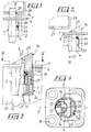
- the device comprises a casing 1 which is composed of a substantially cylindrical cup 2 having respective plane-parallel regions 3 and 4 in opposite positions.
- the cup 2 has a bottom 5 and, at the end opposite to the bottom 5, a flange 6 to which a quadrangular plate 7 is coupled.
- Countersunk holes 8 for the passage of the screws by means of which the device is fixed to the wing of the door are formed at the corners of the plate 7 and of the flange 6. More specifically, the device is inserted in a cylindrical cavity 9 which is open on the upper edge 10 of the wing, so that the flat regions 3 and 4 are at right angles to the plane of said wing.
- a hole 11 is formed in the bottom 5 and eccentrically with respect to the axis A of the cup; the bolt 12 is driven through said hole and engages in the lintel of the walled frame to lock the door in closed position.
- the bolt 12 is constituted by a cylindrical rod which is actuated by the strike lock in a manner that is beyond the scope of the present invention.
- the hole 11 through which the bolt passes is internally tangent to the cup 2, so that the bolt is in tangential contact with the inner wall of the cup along a line 13 which lies in the intermediate centerline plane P which is plane-parallel with respect to the flat regions 3 and 4.
- the bolt 12 is actuated upwards by a spring, not shown, and is operatively associated with a lower bolt, also not shown, so that the actuation of the bolts occurs simultaneously.
- the eccentric position of the bolt 12 allows to place a mechanical sensor 14 between said position and the wall of the cup which lies opposite to the contact point 13; said sensor 14 has the purpose of detecting the closed or open position of the door and consequently releasing or locking the bolt.
- Said sensor 14 is constituted by an element having a substantially U-shaped cross-section which forms, by means of two wings 15 and 16, a semicylindrical channel 17 inside which the bolt 12 is guided.
- the wings 15 and 16 are connected by a thicker portion 18 in which there is a hole 19 which lies at right angles to the axis A of the cup and is ovalized so as to intersect the channel 17.
- a pin 20 is inserted in the hole 19, and its opposite ends engage in slots 21 and 22 formed in the flat regions 3 and 4 of the cup.
- the slots 21 and 22 comprise a lower portion 23 which is parallel to the axis A of the cup and an upper portion 24 which is inclined so that by making the sensor 14 slide in the cup 2 the pin 20 moves transversely in the hole 19.
- the end of the sensor 14 protruding from the cup 2 has a chamfer 25 which affects not only the portion 18 but also the wings 15 and 16 so as to form a sort of latch suitable to retract when the sensor strikes the lintel of the walled frame of the door.
- the described device is completed by a spring 26 which acts by compression, is interposed between the bottom 5 and the sensor 14, and is partially accommodated in a recess 27 of the portion 18.
- Figures 2 and 3 illustrate the device in the condition in which the door is open, i.e. with the bolt 12 in retracted position.
- the lower bolt not shown, is in retracted position as well. Due to the action of the spring 26, the sensor 14 is pushed upwardly so that the pin 20, by following the profile of the slots 21 and 22, is moved laterally in the ovalized hole 19 and is forced against the bolt 12, which is thus locked in retracted position.
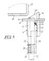
- the sensor 14 due to the abutment of the chamfer 25 against the lintel 28 of the door, is pushed so that it retracts into the cup 2, so as to space the pin 20 from the bolt 12 by means of the slots 21 and 22, thus allowing said bolt to engage the selvage 29 of the lintel by virtue of the action of the spring which pushes it upwards.
- the lower bolt also engages the selvage of the floor.
- the invention perfectly achieves the intended aim.
- the device is easy to install and that by virtue of the chamfer 25 it can compensate for any differences in level between the lintel 28 and the upper edge 10 of the door wing.
- a bracket 30 is rigidly coupled to the cup 2, extends downwardly, and supports a ring 31 which surrounds the bolt.
- a spring 33 is interposed between the ring 31 and a shoulder 32 of the bolt and expels the bolt when the sensor 14 abuts against the lintel 28.
Landscapes
- Engineering & Computer Science (AREA)
- Structural Engineering (AREA)
- Business, Economics & Management (AREA)
- Emergency Management (AREA)
- Lock And Its Accessories (AREA)
- Burglar Alarm Systems (AREA)
Claims (7)
- Dispositif pour verrouiller les boulons actionnés par le verrou percuteur dans une porte de secours à deux battants, comprenant un boítier (1) adapté pour être disposé dans un siège (9) du bord supérieur (10) du battant sur lequel le verrou percuteur est appliqué, ledit boítier (1) comportant un trou (11) pour le passage du boulon (12), un palpeur (14) étant monté coulissant dans ledit boítier, ledit palpeur (14) étant contraint par un ressort (26), ledit palpeur (14) comprenant une goupille (20) mobile transversalement par rapport audit palpeur (14) dans un trou (19) prévu dans ledit palpeur (14) de façon à verrouiller le boulon (12) en position rétractée lorsque ledit palpeur (14) est poussé hors dudit boítier (1) sous l'action dudit ressort (26), le dispositif étant caractérisé en ce que le boulon est une tige cylindrique coulissante (12) et le trou (19) dans ledit palpeur (14) s'étend dans le trajet de la tige cylindrique coulissante de telle sorte que la goupille (20) puisse coopérer de manière libérable avec la surface de la tige cylindrique coulissante, des extrémités opposées de ladite goupille (20) venant au contact coulissant avec des fentes (21, 22) dudit boítier (1), et lesdites fentes (21, 22) étant conformées pour déplacer ladite goupille (20) dans ledit trou (19) dudit palpeur, et ledit palpeur (14) ayant une extrémité munie d'un chanfrein (25) pour coopérer avec un linteau (28) d'un encadrement de la porte.
- Dispositif selon la revendication 1, caractérisé en ce que ledit boítier (1) comprend une coupelle (2) avec un fond (5) dans lequel est prévu un trou excentrique (11) pour le passage dudit boulon (12) et une bride de fixation (6) sur le côté opposé par rapport audit fond (5), ladite coupelle (2) possédant deux régions planes (3, 4) opposées dans lesquelles sont formées lesdites fentes (21, 22).
- Dispositif selon la revendication 2, caractérisé en ce que ledit palpeur (14) possède une section transversale en forme de U avec une portion qui est guidée entre ledit boulon (12) et ladite coupelle (2) et avec deux ailes (15, 16) qui s'enroulent autour dudit boulon (12) et forment un canal (17) pour ledit boulon, ledit trou (19) étant ovalisé de manière à couper ledit canal (17) pour agir sur ledit boulon (12) lorsque ledit palpeur (14) est dans la position dans laquelle il est poussé hors de ladite coupelle (2) sous l'action dudit ressort (26).
- Disposition selon la revendication 3, caractérisé en ce que lesdites fentes (21, 22) au contact desquelles viennent les extrémités opposées de ladite goupille (20) possèdent une portion (23) qui est parallèle à la direction de coulissement du palpeur (14) et une portion (24) qui est inclinée de telle manière que pendant la course pour pousser vers l'extérieur le palpeur (14) sous l'action dudit ressort (26), ledit boulon (20) se déplace le long dudit trou ovalisé (19) pour verrouiller ledit boulon (12).
- Dispositif selon une ou plusieurs des revendications 2 à 4, caractérisé en ce que ledit trou de passage (11) est agencé de manière excentrique dans ladite coupelle (2) de telle sorte que le boulon (12) est en contact tangentiel avec la paroi interne de la coupelle (2).
- Dispositif selon une ou plusieurs des revendications 2 à 5, caractérisé en ce que le ressort (26) qui agit sur ledit palpeur (14) est reçu partiellement dans un renfoncement (27) dudit palpeur et s'appuie sur le fond (5) de la coupelle (2).
- Dispositif selon un ou plusieurs des revendications 1 à 6, caractérisé en ce qu'il comprend un ressort (33) qui agit entre un épaulement (32) du boulon (12) et une bague (31) qui entoure ledit boulon et est fixée à ladite coupelle (2) au moyen d'une console (30), ledit ressort (33) étant adapté pour pousser le boulon vers l'extérieur lorsque ledit palpeur (14) vient buter contre le linteau (28) d'un encadrement de porte.
Applications Claiming Priority (2)
| Application Number | Priority Date | Filing Date | Title |
|---|---|---|---|
| ITBO930329 | 1993-07-21 | ||
| IT93BO000329A IT1264174B1 (it) | 1993-07-21 | 1993-07-21 | Dispositivo per bloccare i chiavistelli comandati dalla contro serratura in una porta di sicurezza a due ante. |
Publications (2)
| Publication Number | Publication Date |
|---|---|
| EP0635611A1 EP0635611A1 (fr) | 1995-01-25 |
| EP0635611B1 true EP0635611B1 (fr) | 1998-01-21 |
Family
ID=11339186
Family Applications (1)
| Application Number | Title | Priority Date | Filing Date |
|---|---|---|---|
| EP94110746A Expired - Lifetime EP0635611B1 (fr) | 1993-07-21 | 1994-07-11 | Dispositif de verrouillage pour pêne actionné par serrure anti-panique d'une porte à deux vantaux |
Country Status (4)
| Country | Link |
|---|---|
| EP (1) | EP0635611B1 (fr) |
| DE (1) | DE69408050T2 (fr) |
| ES (1) | ES2111809T3 (fr) |
| IT (1) | IT1264174B1 (fr) |
Cited By (3)
| Publication number | Priority date | Publication date | Assignee | Title |
|---|---|---|---|---|
| CN101581172B (zh) * | 2009-06-23 | 2011-12-21 | 上海欧一安保器材有限公司 | 一种门受预压状态下开启的门锁结构 |
| DE202012002743U1 (de) | 2012-03-19 | 2012-04-26 | Kfv Karl Fliether Gmbh & Co. Kg | Treibriegel-Schaltschloss |
| DE202012002742U1 (de) | 2012-03-19 | 2012-04-26 | Kfv Karl Fliether Gmbh & Co. Kg | Treibriegel-Schaltschloss |
Families Citing this family (5)
| Publication number | Priority date | Publication date | Assignee | Title |
|---|---|---|---|---|
| IT238933Y1 (it) * | 1995-03-16 | 2001-02-19 | Italiana Serrature Affini | Perfezionamento a un dispositivo per bloccare i chiavistelli in unaporta di sicurezza |
| ES2149062B1 (es) * | 1997-02-17 | 2001-04-16 | Talleres Escoriaza Sa | Dispositivo de punto de cierre alto o bajo, en puertas con cerradura automatica. |
| DE19727365C1 (de) * | 1997-06-27 | 1998-10-22 | Schlechtendahl & Soehne Wilh | Schaltschloß für eine Treibstange in einer Tür oder dergl. |
| ES2199615B1 (es) * | 2000-10-25 | 2005-02-16 | Talleres De Escoriaza, S.A. | Dispositivo de punto alto de cierre para cerraduras de puertas de emergencia. |
| DE102009044654A1 (de) * | 2009-11-25 | 2011-05-26 | Securidev S.A. | Schubstangenschaltschloss |
Family Cites Families (8)
| Publication number | Priority date | Publication date | Assignee | Title |
|---|---|---|---|---|
| DE75175C (de) * | W. S. BUSBY in South-Melbourne, Australien | Schlofs mit Nebenfalle zum Auslösen der Hauptfalle | ||
| US1629641A (en) * | 1924-08-13 | 1927-05-24 | Berger Mfg Co | Lock |
| GB383359A (en) * | 1931-09-26 | 1932-11-17 | Paul Christo Yannedis | Improvements in means for securing and releasing emergency exit doors |
| US2275740A (en) * | 1941-01-10 | 1942-03-10 | Gen Motors Corp | Hood latch |
| GB570685A (en) * | 1943-09-23 | 1945-07-18 | Wilmot Breeden Ltd | Improvements relating to door and like fastenings |
| GB612094A (en) * | 1946-10-04 | 1948-11-08 | Arthur W Adams Ltd | Improvements in or relating to panic bolts and like fastening devices for doors and other closure members |
| US2908523A (en) * | 1957-02-25 | 1959-10-13 | Vonnegut Hardware Company | Vertical rod, top-and-bottom panic latch mechanism |
| US5002321A (en) * | 1990-06-04 | 1991-03-26 | Shy Haw Yaw | Door lock with lightly-closing force |
-
1993
- 1993-07-21 IT IT93BO000329A patent/IT1264174B1/it active IP Right Grant
-
1994
- 1994-07-11 EP EP94110746A patent/EP0635611B1/fr not_active Expired - Lifetime
- 1994-07-11 DE DE69408050T patent/DE69408050T2/de not_active Expired - Fee Related
- 1994-07-11 ES ES94110746T patent/ES2111809T3/es not_active Expired - Lifetime
Cited By (6)
| Publication number | Priority date | Publication date | Assignee | Title |
|---|---|---|---|---|
| CN101581172B (zh) * | 2009-06-23 | 2011-12-21 | 上海欧一安保器材有限公司 | 一种门受预压状态下开启的门锁结构 |
| DE202012002743U1 (de) | 2012-03-19 | 2012-04-26 | Kfv Karl Fliether Gmbh & Co. Kg | Treibriegel-Schaltschloss |
| DE202012002742U1 (de) | 2012-03-19 | 2012-04-26 | Kfv Karl Fliether Gmbh & Co. Kg | Treibriegel-Schaltschloss |
| EP2642051A2 (fr) | 2012-03-19 | 2013-09-25 | KFV Karl Fliether GmbH & Co. KG | Verrou relâché lors de la fermeture d'une porte |
| EP2642052A2 (fr) | 2012-03-19 | 2013-09-25 | KFV Karl Fliether GmbH & Co. KG | Verrou relâché lors de la fermeture d'une porte |
| EP2642051A3 (fr) * | 2012-03-19 | 2017-11-29 | KFV Karl Fliether GmbH & Co. KG | Verrou relâché lors de la fermeture d'une porte |
Also Published As
| Publication number | Publication date |
|---|---|
| IT1264174B1 (it) | 1996-09-23 |
| ITBO930329A0 (it) | 1993-07-21 |
| DE69408050D1 (de) | 1998-02-26 |
| ITBO930329A1 (it) | 1995-01-21 |
| DE69408050T2 (de) | 1998-08-20 |
| EP0635611A1 (fr) | 1995-01-25 |
| ES2111809T3 (es) | 1998-03-16 |
Similar Documents
| Publication | Publication Date | Title |
|---|---|---|
| US3680901A (en) | Bolt assembly | |
| US6174004B1 (en) | Mortise latch and exit device with concealed vertical rods | |
| US9097043B2 (en) | Multi-point locking system and astragal | |
| US3556573A (en) | Astragal mounted flush bolt | |
| US5636880A (en) | Electronic lock | |
| US4545606A (en) | Door latch assembly | |
| EP0635611B1 (fr) | Dispositif de verrouillage pour pêne actionné par serrure anti-panique d'une porte à deux vantaux | |
| US4204369A (en) | Entrance door system with automatic astragal and panic device | |
| EP3336291B1 (fr) | Ensemble à double verrouillage pour structures ouvrables | |
| EP3336285B1 (fr) | Ensembles verrou de fermeture | |
| US5673948A (en) | Remote lock operation control means | |
| US4087121A (en) | Dead bolt lock | |
| US2781218A (en) | Latch unit for panic exit lock | |
| US3600022A (en) | Exit device vertical rod upper latching and holddown mechanism | |
| US3149864A (en) | Latch mechanism | |
| US2777721A (en) | Refrigerator latch | |
| GB2225607A (en) | Improvements in or relating to locks | |
| EP0732472B1 (fr) | Dispositif pour le blocage de pênes dans une porte de sécurité | |
| EP0992645A1 (fr) | Dispositif de verrouillage automatique pour battants de porte ou fenêtre | |
| EP0620342B1 (fr) | Verrou pour serrure, notamment pour serrures anti-paniques pour portes deux battants | |
| EP2584132A1 (fr) | Dispositif de sécurité du type anti-fausse manoeuvre pour espagnolettes | |
| CA2883182C (fr) | Montant de blocage dote d'une tige de blocage reglable | |
| EP3702558B1 (fr) | Contre-serrure d'un battant inactif d'une porte à deux battants | |
| CA2299597C (fr) | Loquet a mortaise et dispositif de sortie de secours a barres verticales dissimulees | |
| US2732241A (en) | scheidler |
Legal Events
| Date | Code | Title | Description |
|---|---|---|---|
| PUAI | Public reference made under article 153(3) epc to a published international application that has entered the european phase |
Free format text: ORIGINAL CODE: 0009012 |
|
| AK | Designated contracting states |
Kind code of ref document: A1 Designated state(s): DE ES NL |
|
| 17P | Request for examination filed |
Effective date: 19950619 |
|
| 17Q | First examination report despatched |
Effective date: 19960419 |
|
| GRAG | Despatch of communication of intention to grant |
Free format text: ORIGINAL CODE: EPIDOS AGRA |
|
| GRAG | Despatch of communication of intention to grant |
Free format text: ORIGINAL CODE: EPIDOS AGRA |
|
| GRAH | Despatch of communication of intention to grant a patent |
Free format text: ORIGINAL CODE: EPIDOS IGRA |
|
| GRAH | Despatch of communication of intention to grant a patent |
Free format text: ORIGINAL CODE: EPIDOS IGRA |
|
| GRAA | (expected) grant |
Free format text: ORIGINAL CODE: 0009210 |
|
| AK | Designated contracting states |
Kind code of ref document: B1 Designated state(s): DE ES NL |
|
| REF | Corresponds to: |
Ref document number: 69408050 Country of ref document: DE Date of ref document: 19980226 |
|
| REG | Reference to a national code |
Ref country code: ES Ref legal event code: FG2A Ref document number: 2111809 Country of ref document: ES Kind code of ref document: T3 |
|
| PLBE | No opposition filed within time limit |
Free format text: ORIGINAL CODE: 0009261 |
|
| STAA | Information on the status of an ep patent application or granted ep patent |
Free format text: STATUS: NO OPPOSITION FILED WITHIN TIME LIMIT |
|
| 26N | No opposition filed | ||
| PGFP | Annual fee paid to national office [announced via postgrant information from national office to epo] |
Ref country code: NL Payment date: 20090731 Year of fee payment: 16 Ref country code: DE Payment date: 20090813 Year of fee payment: 16 |
|
| REG | Reference to a national code |
Ref country code: NL Ref legal event code: V1 Effective date: 20110201 |
|
| PG25 | Lapsed in a contracting state [announced via postgrant information from national office to epo] |
Ref country code: DE Free format text: LAPSE BECAUSE OF NON-PAYMENT OF DUE FEES Effective date: 20110201 |
|
| REG | Reference to a national code |
Ref country code: DE Ref legal event code: R119 Ref document number: 69408050 Country of ref document: DE Effective date: 20110201 |
|
| PG25 | Lapsed in a contracting state [announced via postgrant information from national office to epo] |
Ref country code: NL Free format text: LAPSE BECAUSE OF NON-PAYMENT OF DUE FEES Effective date: 20110201 |
|
| PGFP | Annual fee paid to national office [announced via postgrant information from national office to epo] |
Ref country code: ES Payment date: 20120730 Year of fee payment: 19 |
|
| REG | Reference to a national code |
Ref country code: ES Ref legal event code: FD2A Effective date: 20140908 |
|
| PG25 | Lapsed in a contracting state [announced via postgrant information from national office to epo] |
Ref country code: ES Free format text: LAPSE BECAUSE OF NON-PAYMENT OF DUE FEES Effective date: 20130712 |