EP0638227A2 - Trailing hose system for liquid manure vehicle - Google Patents
Trailing hose system for liquid manure vehicle Download PDFInfo
- Publication number
- EP0638227A2 EP0638227A2 EP94111915A EP94111915A EP0638227A2 EP 0638227 A2 EP0638227 A2 EP 0638227A2 EP 94111915 A EP94111915 A EP 94111915A EP 94111915 A EP94111915 A EP 94111915A EP 0638227 A2 EP0638227 A2 EP 0638227A2
- Authority
- EP
- European Patent Office
- Prior art keywords
- cutter
- hoses
- trailing
- plate
- ring
- Prior art date
- Legal status (The legal status is an assumption and is not a legal conclusion. Google has not performed a legal analysis and makes no representation as to the accuracy of the status listed.)
- Granted
Links
Images


Classifications
-
- A—HUMAN NECESSITIES
- A01—AGRICULTURE; FORESTRY; ANIMAL HUSBANDRY; HUNTING; TRAPPING; FISHING
- A01C—PLANTING; SOWING; FERTILISING
- A01C23/00—Distributing devices specially adapted for liquid manure or other fertilising liquid, including ammonia, e.g. transport tanks or sprinkling wagons
- A01C23/001—Sludge spreaders, e.g. liquid manure spreaders
- A01C23/002—Sludge spreaders, e.g. liquid manure spreaders provided with auxiliary arrangements, e.g. pumps, agitators, cutters
-
- A—HUMAN NECESSITIES
- A01—AGRICULTURE; FORESTRY; ANIMAL HUSBANDRY; HUNTING; TRAPPING; FISHING
- A01C—PLANTING; SOWING; FERTILISING
- A01C23/00—Distributing devices specially adapted for liquid manure or other fertilising liquid, including ammonia, e.g. transport tanks or sprinkling wagons
- A01C23/008—Tanks, chassis or related parts
Definitions
- the present invention relates to a trailing hose system of the kind described in the introductory part of claim 1.
- Claim 2 relates to a preferred embodiment of a cutting distributor for a trailing hose system according to the invention in which the cutting distributor is embodied with a cutter plate and a belonging cutter ring.
- Claim 3 relates to a preferred embodiment of a cutting distributor for a trailing hose system according to the invention in which the cutting distributor is embodied with two cutter plates with belonging cutter rings.
- Claim 4 relates to a preferred placing of air admission openings to the cutting distributor of a trailing hose system according to the invention.
- any liquid manure leaking into the innermost, air-filled space, is hurled outward towards the outlet openings.
- the boom is kept in an essentially horizontal position and as far as possible follows roughnesses in the terrain, and that when the booms are raised and folded up on the side of liquid manure vehicle after the finished spreading, they are inclined in the upward direction away from the suspension mount, so that any possible remaining liquid manure stays in the hoses during transportation.
- a trailing hose system As shown in figs. 1 and 2 a trailing hose system according to the kind described in the application consists of a spreading boom 2 mounted on a liquid manure vehicle 1 by a mount 3. Below the spreading boom 2 are mounted a number of trailing hoses 4 which by means of connecting hoses 5 are connected to a cutting distributor which is supplied with liquid manure from the liquid manure vehicle by means of a not shown pump.
- a cutting distributor 6 of a hose system consists of a cutter plate 7 with a number of outlet holes for liquid manure 8 which preferably have a uniform diameter and are arranged with a definite mutual distance.
- the number of holes 8 corresponds to the number of trailing hoses 4.
- the cutting distributor 6 is embodied with connecting pieces 9 for the hoses 5.
- Above the cutter plate 7 is mounted a cutter ring 10 which has a plane under side 11 and which can be displaced on the likewise plane upper side 12 of the cutter ring 7.
- a piston 13 On top of the cutter ring 10 is mounted a piston 13 shaped as a cylindrical ring, which along its outside edge 14 on the under side is embodied with a recess or a groove with a horizontal surface 15 making full contact against a plane upper side 16 of the cutter ring 10, and with a vertical surface 18 making full contact against the internal, vertical edge 19 of the cutter ring 10.
- the piston 13 On its upper side the piston 13 is actuated by a downward directed spring force, for example from an O-ring 21, whereby the cutter ring 10 is forced down against the cutter plate 7.
- the internal edge 22 of the piston 13 is loosely meshing with the external side on a ring-shaped rib 23, which is mounted on the under side of a circular plate 24 a distance behind the outermost edge 25 of the same.
- the plate 24 At its centre the plate 24 has a circular cut-out 26 in which an excentric 27 on a shaft 28 can be accommodated.
- the shaft 28 is coupled to a drive motor 29.
- the circular plate 24 can have an upper side embodied with a rib 23', which is placed above and has the same dimension as the rib 23.
- On top of the plate 24 is mounted another piston 13' whose innermost edge 22' is meshing with the the rib 23'.
- the piston 13' is embodied identical with the piston 13, but mounted laterally reversed - round a central plane o-o through the plate 24 - in relation to it.
- the piston 13' is meshing with another cutter ring 10', which comes to rest against another cutter plate 7'.
- the circular plate 24 is embodied with a number of air holes 30.
- the parts are built into a housing 31 consisting of a first, closed chamber 32 outside the cutter rings 10,10' and a second, closed chamber 33 inside the cutter rings 10,10'.
- the chamber 32 is supplied with liquid manure, and the chamber 33 receives air through the openings 30.
- the chamber 33 can incorporate a number of wings 34, which are mounted on and participate in the rotation of the shalt 28. Thereby any possible liquid manure, which may have leaked into the chamber 33, is hurled outwards towards the periphery and away through the outlet holes 8.
- the cutting distributor 6 can be mounted with the outlet holes 8,8' facing each towards its own end of a boom, when the booms are swung out in their working position.
- the hoses 5 can be inserted in the cutting distributor without sharp bends or curves, whereby the resistance is reduced and it is prevented that the hoses are damaged or suffer too much stress during use.
- the mount 3 can consist of two parallel, vertical sectional irons 35.
- the frame 40 of the trailing hose system is attached to each sectional iron 35 by means of two approximately parallel guide rods 36 and 37 which are swingably attached to the frame 40 and to a sectional iron 35 by means of pins 38 and 39, respectively.
- the rod 37 is adjustable lengthwise and shorter than the rod 36.
- the frame 40 can be raised and lowered by means of two hydraulic cylinders 41 which at each end are swingably hinged on a pin 42 to a sectional iron 35 and in the piston rod end are swingably hinged on a pin 43 to a mount 44 on the frame 40.
- the compression side of the two cylinders 41 are mutually connected.
- the booms are therefore held in the horizontal position irrespective of roughnesses in the terrain.
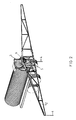
- the frame 40 When the frame 40 is in its lowered position it will, as shown in fig. 7, be vertical.
- it When it is in its raised position it will, as shown in fig. 8 be inclined backwards, whereby the booms, when they are swung up on the side of the liquid manure vehicle, take up the position shown in fig. 11, in which the booms are slightly inclined rearwards so that any possible remaining liquid manure stays in the hoses.
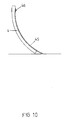
- each trailing hose 4 can be fitted with a steel rod 45, for example of spring steel, which is attached to a hose 4by a rivet or bolt connection 46, and which at the bottom end protrudes a short distance outside the hose.
- This steel rod prevents the hose from breaking on contact with the ground.
- the spring force may be supplied in ways other than by means of an O-ring.
Landscapes
- Life Sciences & Earth Sciences (AREA)
- Engineering & Computer Science (AREA)
- Water Supply & Treatment (AREA)
- Soil Sciences (AREA)
- Environmental Sciences (AREA)
- Catching Or Destruction (AREA)
- Earth Drilling (AREA)
- Forklifts And Lifting Vehicles (AREA)
- Filling Or Emptying Of Bunkers, Hoppers, And Tanks (AREA)
Abstract
Description
- The present invention relates to a trailing hose system of the kind described in the introductory part of claim 1.
- Such a trailing hose system is known from UK patent application No. 2 251 166.
- It is a drawback in the said known system that the flow of liquid manure out into the trailing hoses is pulsating, and uneven and that there is a great loss of pressure in the system. The individual connecting hoses between the cutting distributor and the trailing hoses have to be bent in order to be connected to the cutting distributor, which results in a heavy wear on the hoses each time the booms are swung up alongside the liquid manure tank vehicle and back again. Furthermore, the knife function in the cutting distributor is insufficient, wherefore the system easily clogs up with bits of straw which are present in the liquid manure.
- It is the purpose of the present invention to define a trailing hose system without the drawbacks of the known systems. This is achieved by embodying a trailing hose system of the kind described in the introductory part of claim 1 as stated in the characterizing part of the claim.
- This ensures that the cutting distributor can be fitted with the cutter plate facing the connecting hoses so that the hoses can be mounted without sharp bends. The top end of the hoses at the cutting distributor is under atmospheric pressure internally, whereby the liquid manure is passed through the hoses in an even flow with a minimum pressure drop. Furthermore, a self-sharpening effect on the cutter ring is achieved by the excentric movement of the latter in relation to the cutter plate, whereby the straw pieces in the liquid manure are effectively shredded.
- Claim 2 relates to a preferred embodiment of a cutting distributor for a trailing hose system according to the invention in which the cutting distributor is embodied with a cutter plate and a belonging cutter ring.
-
Claim 3 relates to a preferred embodiment of a cutting distributor for a trailing hose system according to the invention in which the cutting distributor is embodied with two cutter plates with belonging cutter rings. -
Claim 4 relates to a preferred placing of air admission openings to the cutting distributor of a trailing hose system according to the invention. - According to the description in
claim 5 any liquid manure leaking into the innermost, air-filled space, is hurled outward towards the outlet openings. - According to the description in
claim 6 the boom is kept in an essentially horizontal position and as far as possible follows roughnesses in the terrain, and that when the booms are raised and folded up on the side of liquid manure vehicle after the finished spreading, they are inclined in the upward direction away from the suspension mount, so that any possible remaining liquid manure stays in the hoses during transportation. - According to the description in
claim 7 it is ensured that the trailing hoses do not break on contact with the ground. - The invention is explained in detail below with reference to the drawing in which
- fig. 1
- is a rear view of a liquid manure vehicle with a trailing hose system according to the invention,
- fig. 2
- is a perspective view of a liquid manure cart with a trailing hose system according to the invention,
- fig. 3
- is a perspective view of parts of a cutting distributor of a trailing hose system according to the invention,
- fig. 4
- is a schematic illustration of a vertical section through a cutting distributor of a trailing hose system according to the invention,
- fig. 5
- shows a cutting distributor for a trailing hose system according to the invention seen from above with the top cover removed,
- fig. 6
- shows a section after the line I-I in fig. 4,
- fig. 7
- is a side view of a suspension arrangement of a trailing hose system according to the invention in which the boom is in its lowered working position,
- fig. 8
- shows the same details as fig. 7, but the boom is here in the raised position,
- fig. 9
- is a perspective view of the suspension arrangement shown in fig. 8,
- fig. 10
- is a section of the lowest part of a trailing hose with a built-in steel rod,
- fig. 11
- is a side view of a liquid manure vehicle with a trailing hose system according to the invention and with one boom swung up along the side of the liquid manure vehicle.
- As shown in figs. 1 and 2 a trailing hose system according to the kind described in the application consists of a spreading boom 2 mounted on a liquid manure vehicle 1 by a
mount 3. Below the spreading boom 2 are mounted a number of trailinghoses 4 which by means of connectinghoses 5 are connected to a cutting distributor which is supplied with liquid manure from the liquid manure vehicle by means of a not shown pump. - As shown in fig. 3 a
cutting distributor 6 of a hose system according to the invention consists of acutter plate 7 with a number of outlet holes forliquid manure 8 which preferably have a uniform diameter and are arranged with a definite mutual distance. The number ofholes 8 corresponds to the number of trailinghoses 4. At theholes 8 thecutting distributor 6 is embodied with connectingpieces 9 for thehoses 5. Above thecutter plate 7 is mounted acutter ring 10 which has a plane underside 11 and which can be displaced on the likewise planeupper side 12 of thecutter ring 7. On top of thecutter ring 10 is mounted apiston 13 shaped as a cylindrical ring, which along itsoutside edge 14 on the under side is embodied with a recess or a groove with ahorizontal surface 15 making full contact against a planeupper side 16 of thecutter ring 10, and with avertical surface 18 making full contact against the internal,vertical edge 19 of thecutter ring 10. On its upper side thepiston 13 is actuated by a downward directed spring force, for example from an O-ring 21, whereby thecutter ring 10 is forced down against thecutter plate 7. Theinternal edge 22 of thepiston 13 is loosely meshing with the external side on a ring-shaped rib 23, which is mounted on the under side of a circular plate 24 a distance behind theoutermost edge 25 of the same. At its centre theplate 24 has a circular cut-out 26 in which an excentric 27 on ashaft 28 can be accommodated. Theshaft 28 is coupled to adrive motor 29. - As shown in fig. 4 the
circular plate 24 can have an upper side embodied with a rib 23', which is placed above and has the same dimension as therib 23. On top of theplate 24 is mounted another piston 13' whose innermost edge 22' is meshing with the the rib 23'. The piston 13' is embodied identical with thepiston 13, but mounted laterally reversed - round a central plane o-o through the plate 24 - in relation to it. The piston 13' is meshing with another cutter ring 10', which comes to rest against another cutter plate 7'. - The
circular plate 24 is embodied with a number ofair holes 30. - As shown the parts are built into a
housing 31 consisting of a first, closedchamber 32 outside thecutter rings 10,10' and a second, closedchamber 33 inside thecutter rings 10,10'. Thechamber 32 is supplied with liquid manure, and thechamber 33 receives air through theopenings 30. - When the
shaft 28 rotates, acutter ring 10 will open and close for admission of liquid manure to alloutlet holes 8. Furthermore, air is supplied to all outlet holes so that the atmospheric pressure reigns in the uppermost part of thehoses 5. As a consequence of this ahose belonging outlet hole 8. The resist ance in the system is therefore at a minimum and the throughput of liquid manure at a maximum. - As shown in fig. 6 the
chamber 33 can incorporate a number ofwings 34, which are mounted on and participate in the rotation of theshalt 28. Thereby any possible liquid manure, which may have leaked into thechamber 33, is hurled outwards towards the periphery and away through theoutlet holes 8. - As shown in figs. 1 and 2 the
cutting distributor 6 can be mounted with theoutlet holes 8,8' facing each towards its own end of a boom, when the booms are swung out in their working position. Hereby thehoses 5 can be inserted in the cutting distributor without sharp bends or curves, whereby the resistance is reduced and it is prevented that the hoses are damaged or suffer too much stress during use. - As shown in figs. 7-9 the
mount 3 can consist of two parallel, verticalsectional irons 35. Theframe 40 of the trailing hose system is attached to eachsectional iron 35 by means of two approximatelyparallel guide rods frame 40 and to asectional iron 35 by means ofpins rod 37 is adjustable lengthwise and shorter than therod 36. Theframe 40 can be raised and lowered by means of twohydraulic cylinders 41 which at each end are swingably hinged on apin 42 to asectional iron 35 and in the piston rod end are swingably hinged on apin 43 to amount 44 on theframe 40. The compression side of the twocylinders 41 are mutually connected. The booms are therefore held in the horizontal position irrespective of roughnesses in the terrain. When theframe 40 is in its lowered position it will, as shown in fig. 7, be vertical. When it is in its raised position it will, as shown in fig. 8 be inclined backwards, whereby the booms, when they are swung up on the side of the liquid manure vehicle, take up the position shown in fig. 11, in which the booms are slightly inclined rearwards so that any possible remaining liquid manure stays in the hoses. - As shown in fig. 10 the lowest end of each trailing
hose 4 can be fitted with asteel rod 45, for example of spring steel, which is attached to a hose 4by a rivet orbolt connection 46, and which at the bottom end protrudes a short distance outside the hose. This steel rod prevents the hose from breaking on contact with the ground. - The shown and described embodiments are only meant to serve as an example of the invention. Within the framework of the invention various modifications can be imagined. For example, the spring force may be supplied in ways other than by means of an O-ring.
Claims (7)
- Trailing hose system which is mounted on a liquid manure vehicle (1) by means of a mount (3) and which comprises a spreading boom (2) with a number of trailing hoses (4) and a cutting distributor (6), which through hoses (5) is connected to the trailing hoses (4), characterized in that the cutting distributor (6) comprises at least one cutter plate (7) with a number of outlet holes (8) for connection of hoses (5) and a belonging cutter ring (10), whose thickness is less than the diameter of a hole (8) and which has a plane side (11), which comes to rest against a plane surface (12) of the cutter plate (7), means (13,21) to hold the cutter ring (10) thrust into contact with the cutter plate (7) and means (13,24,27) to give the cutter ring (10) an excentric movement, whereby the openings (8) are opened and closed all the way round, that the cutter plate (7) and the cutter ring (10) are built into a housing (31) in such a way that the area outside the cutter ring (10) is embodied as a first chamber (32) to which liquid manure is supplied, and that the area inside the cutter ring (10) is embodied as second chamber (33) which is under ambient atmospheric pressure, and that the cutting distributor preferably is placed at a level so that the liquid manure is led from the cutting distributor through the hoses (5) and (4) by a free fall.
- Trailing hose system according to claim 1, characterized in that the cutting distributor (6) comprises a pressure plate or a piston (13) shaped as a cylinder ring whose outside edge (14) on the under side has a turned recess with a horizontal surface (15) coming to rest against side (16) opposite the plane surface (11) of the cutter ring (10), and with a vertical surface (18), which rests against the internal, vertical edge (19) adjoining the side (16) of the cutter ring (10), which piston (13) on its upper side (20) is actuated by a spring force, for example from an O-ring (21), in the direction against the cutter plate (7), and which along the internal edge (22) is loosely meshing with a vertical, ring-shaped rib (23) which is mounted on the under side of and a distance behind the outer edge (25) of a circular plate (24), which at its centre has a circular-section opening (26) which is meshing with an excentric (27) on a shaft (28), which is coupled to a drive motor (29).
- Trailing hose system according to claim 1 characterized in that the circular plate (24) on its upper side is embodied with a second rib (23') which is placed vertically over and has the same dimensions as the rib (23), that on top of the plate (24) is fitted a second piston (13') whose internal edge (22') is meshing with the rib (23'), and a second cutter ring (10') and a second cutter plate (7') which has the same dimensions as the piston (13), the cutter ring (10) and the cutter plate (7), respectively, but is laterally reversed in relation to it round a central plane (o-o) through the plate (24), and that be-tween the pistons (13) and (13') an O-ring (21) is mounted, which - when the parts are assembled and tightened - supplies the necessary elastic force which keeps the cutter rings (10) and (10') forced against the cutter plates (7) and (7'), respectively.
- Trailing hose system according to claims 1-3, characterized in that the plate (24) inside the rib (23) is embodied with a number of air holes (30).
- Trailing hose system according to claims 1-3, characterized in that a number of wings (34) are rigidly fitted to the shaft (28) are mounted in the chamber (33).
- Trailing hose system according to claims 1-3, characterized in that the mount (3) is embodied as two parallel, vertical rods (35) at a distance from each other, and that the frame (40) of the trailing hose system is attached to each sectional iron (35) by two approximately parallel guide rods (36) and (37) which are swingably attached to the frame (40) and a sectional iron (35) by pins (38) and (39), respectively, that the lower rod (37) is a little shorter that the upper (36) and that the frame 40) can be raised and lowered by means of two hydrolic cylinders (41), which each at the cylinder end is swingably hinged to a sectional iron (35) by a pin (42) and at the piston rod end to a mount (44) at the top of the frame (40) by a pin (43), and that the pressure sides of the cylinders (41) are mutually connected.
- Trailing hose system according to claims 1-3, chacterized in that a steel rod (45) is fitted inside the lowest portion of each trailing hose (4).
Applications Claiming Priority (3)
| Application Number | Priority Date | Filing Date | Title |
|---|---|---|---|
| DK91893 | 1993-08-09 | ||
| DK091893A DK170545B1 (en) | 1993-08-09 | 1993-08-09 | slurry spreaders |
| DK918/93 | 1993-08-09 |
Publications (3)
| Publication Number | Publication Date |
|---|---|
| EP0638227A2 true EP0638227A2 (en) | 1995-02-15 |
| EP0638227A3 EP0638227A3 (en) | 1995-09-13 |
| EP0638227B1 EP0638227B1 (en) | 1998-11-11 |
Family
ID=8099009
Family Applications (1)
| Application Number | Title | Priority Date | Filing Date |
|---|---|---|---|
| EP94111915A Expired - Lifetime EP0638227B1 (en) | 1993-08-09 | 1994-07-29 | Trailing hose system for liquid manure vehicle |
Country Status (3)
| Country | Link |
|---|---|
| EP (1) | EP0638227B1 (en) |
| DE (2) | DE69414485T2 (en) |
| DK (1) | DK170545B1 (en) |
Cited By (8)
| Publication number | Priority date | Publication date | Assignee | Title |
|---|---|---|---|---|
| EP1656822A1 (en) * | 2004-11-12 | 2006-05-17 | Harry Sörensen | Distributor unit for distribution of a liquid such as slurry for a slurry spreader to several outlets, and a method |
| EP1915895A2 (en) | 2006-10-23 | 2008-04-30 | Sörensen, Harry | Dispenser for dividing a main flow of a fluid into a number of partial fluids |
| US8899496B2 (en) | 2009-12-18 | 2014-12-02 | Carbofibretec Gmbh | Horizontally pivotable agricultural sprayer with vertically pivotable segments |
| JP2015072066A (en) * | 2013-09-19 | 2015-04-16 | フーゴ・フォーゲルザング・マシネンバウ・ゲゼルシャフト・ミット・ベシュレンクテル・ハフツングHugo Vogelsang Maschinenbau Gmbh | Distributing device for solid-containing liquid |
| DK201400478A1 (en) * | 2014-08-28 | 2016-03-07 | Harry Højvang Sørensen | Lubrication system for manure distributors with eccentric working cutters. |
| CN112136457A (en) * | 2020-09-18 | 2020-12-29 | 河海大学 | Self-leveling type water conservancy sprinkling irrigation device |
| GB2625275A (en) * | 2022-12-12 | 2024-06-19 | Srf Ltd | An Apparatus for Spreading Slurry and a Boom Assembly Therefor |
| EP4649808A1 (en) | 2024-05-16 | 2025-11-19 | Ets JOSKIN S.A. | Quick-release distributor |
Families Citing this family (3)
| Publication number | Priority date | Publication date | Assignee | Title |
|---|---|---|---|---|
| DE202011050654U1 (en) | 2011-07-07 | 2011-10-19 | Stapel Gmbh | Distributor device for a solids-laden liquid |
| DE102022120270A1 (en) * | 2022-08-11 | 2024-02-22 | Alrena B.V. | Distributor and method for clamping a rotor for a distributor and for distributing liquid substances |
| CN117256287B (en) * | 2023-11-20 | 2024-02-27 | 中国农业大学 | Anti-blocking turbulent flow type liquid organic fertilizer accurate distributor and fertilizing equipment |
Citations (1)
| Publication number | Priority date | Publication date | Assignee | Title |
|---|---|---|---|---|
| GB2251166A (en) | 1990-12-27 | 1992-07-01 | Joseph Cavanagh | Slurry spreaders |
Family Cites Families (2)
| Publication number | Priority date | Publication date | Assignee | Title |
|---|---|---|---|---|
| DE8910777U1 (en) * | 1989-09-09 | 1989-10-26 | Hugo Vogelsang Faß- und Maschinenbau GmbH, 4572 Essen | Device for distributing inhomogeneous, solid-laden liquids, especially liquid manure |
| DE4136162C1 (en) * | 1991-11-02 | 1992-09-10 | Karl 4409 Havixbeck De Stade | Distributor attached to mobile slurry containers - has central pipe passing slurry into rotatable disc-shaped head |
-
1993
- 1993-08-09 DK DK091893A patent/DK170545B1/en not_active IP Right Cessation
-
1994
- 1994-07-29 EP EP94111915A patent/EP0638227B1/en not_active Expired - Lifetime
- 1994-07-29 DE DE69414485T patent/DE69414485T2/en not_active Expired - Fee Related
- 1994-08-04 DE DE9412577U patent/DE9412577U1/en not_active Expired - Lifetime
Patent Citations (1)
| Publication number | Priority date | Publication date | Assignee | Title |
|---|---|---|---|---|
| GB2251166A (en) | 1990-12-27 | 1992-07-01 | Joseph Cavanagh | Slurry spreaders |
Cited By (14)
| Publication number | Priority date | Publication date | Assignee | Title |
|---|---|---|---|---|
| EP1656822A1 (en) * | 2004-11-12 | 2006-05-17 | Harry Sörensen | Distributor unit for distribution of a liquid such as slurry for a slurry spreader to several outlets, and a method |
| EP1915895A2 (en) | 2006-10-23 | 2008-04-30 | Sörensen, Harry | Dispenser for dividing a main flow of a fluid into a number of partial fluids |
| EP1915895A3 (en) * | 2006-10-23 | 2009-03-25 | Sörensen, Harry | Dispenser for dividing a main flow of a fluid into a number of partial fluids |
| US8899496B2 (en) | 2009-12-18 | 2014-12-02 | Carbofibretec Gmbh | Horizontally pivotable agricultural sprayer with vertically pivotable segments |
| JP2015072066A (en) * | 2013-09-19 | 2015-04-16 | フーゴ・フォーゲルザング・マシネンバウ・ゲゼルシャフト・ミット・ベシュレンクテル・ハフツングHugo Vogelsang Maschinenbau Gmbh | Distributing device for solid-containing liquid |
| DK178936B1 (en) * | 2014-08-28 | 2017-06-12 | Harry Højvang Sørensen | SLURRY DISTRIBUTOR |
| DK201400478A1 (en) * | 2014-08-28 | 2016-03-07 | Harry Højvang Sørensen | Lubrication system for manure distributors with eccentric working cutters. |
| CN112136457A (en) * | 2020-09-18 | 2020-12-29 | 河海大学 | Self-leveling type water conservancy sprinkling irrigation device |
| GB2625275A (en) * | 2022-12-12 | 2024-06-19 | Srf Ltd | An Apparatus for Spreading Slurry and a Boom Assembly Therefor |
| GB2625275B (en) * | 2022-12-12 | 2025-04-09 | Srf Ltd | An Apparatus for Spreading Slurry and a Boom Assembly Therefor |
| IE20230526A1 (en) * | 2022-12-12 | 2025-10-08 | Srf Ltd | An apparatus for spreading slurry and a Boom Assembly Therefor |
| IE87695B1 (en) * | 2022-12-12 | 2026-01-28 | Srf Ltd | An apparatus for spreading slurry and a boom assembly therefor |
| EP4649808A1 (en) | 2024-05-16 | 2025-11-19 | Ets JOSKIN S.A. | Quick-release distributor |
| BE1032619A1 (en) | 2024-05-16 | 2025-12-12 | Ets Joskin S A | QUICK-OPENING DISPENSER |
Also Published As
| Publication number | Publication date |
|---|---|
| EP0638227A3 (en) | 1995-09-13 |
| DK170545B1 (en) | 1995-10-23 |
| DK91893A (en) | 1995-02-10 |
| DK91893D0 (en) | 1993-08-09 |
| EP0638227B1 (en) | 1998-11-11 |
| DE9412577U1 (en) | 1994-10-20 |
| DE69414485D1 (en) | 1998-12-17 |
| DE69414485T2 (en) | 1999-06-24 |
Similar Documents
| Publication | Publication Date | Title |
|---|---|---|
| EP0638227A2 (en) | Trailing hose system for liquid manure vehicle | |
| US5060732A (en) | Cylinder-type ground-raking attachment for a bucket-equipped tractor | |
| DE60130805T2 (en) | BAGGER CUTTING HEAD | |
| US4756626A (en) | Fluent and nonfluent material mixer | |
| CN111167550A (en) | Fertilizer triturating device for agricultural use | |
| EP3058800A1 (en) | An impeller pump | |
| US5528844A (en) | Excavating apparatus with a compression plate and associated hydraulic cylinder for the dewatering of excavation material | |
| DE1458619A1 (en) | Hydraulic grab cage | |
| US5154363A (en) | Reciprocating action miller | |
| CN105684579B (en) | Fan type incomplete film-recovering machine | |
| DE9108952U1 (en) | Floating grab system for the extraction of sand and gravel | |
| KR102446544B1 (en) | Skid loader mounted chicken manure collection device | |
| US2957430A (en) | Cement pump unit | |
| US2858625A (en) | Material removal unit for selfpropelled vehicle | |
| DE1484701A1 (en) | Suction dredger, digging and suction unit as well as method for; operating this suction dredger | |
| CN207287659U (en) | A kind of feed stuff reducing device for poultry feeder assembly | |
| CN211190440U (en) | Reducing mechanism is used in chinese patent medicine processing | |
| US4445823A (en) | Animal waste pumping system | |
| US4278408A (en) | Manure transfer pump | |
| CN214090042U (en) | Shell hopper with soil cleaning function | |
| US3289332A (en) | Tractor scraper blade | |
| CN213740958U (en) | Reservoir floater cleaning device | |
| US5669712A (en) | Concrete placer attachment for skid steer loaders | |
| US3844540A (en) | Method and apparatus for unclogging fluid pump intakes | |
| DE2516683C3 (en) | Garbage compactor |
Legal Events
| Date | Code | Title | Description |
|---|---|---|---|
| PUAI | Public reference made under article 153(3) epc to a published international application that has entered the european phase |
Free format text: ORIGINAL CODE: 0009012 |
|
| AK | Designated contracting states |
Kind code of ref document: A2 Designated state(s): BE DE FR GB NL SE |
|
| PUAL | Search report despatched |
Free format text: ORIGINAL CODE: 0009013 |
|
| AK | Designated contracting states |
Kind code of ref document: A3 Designated state(s): BE DE FR GB NL SE |
|
| 17P | Request for examination filed |
Effective date: 19960130 |
|
| GRAG | Despatch of communication of intention to grant |
Free format text: ORIGINAL CODE: EPIDOS AGRA |
|
| GRAG | Despatch of communication of intention to grant |
Free format text: ORIGINAL CODE: EPIDOS AGRA |
|
| GRAH | Despatch of communication of intention to grant a patent |
Free format text: ORIGINAL CODE: EPIDOS IGRA |
|
| 17Q | First examination report despatched |
Effective date: 19980421 |
|
| GRAH | Despatch of communication of intention to grant a patent |
Free format text: ORIGINAL CODE: EPIDOS IGRA |
|
| GRAA | (expected) grant |
Free format text: ORIGINAL CODE: 0009210 |
|
| AK | Designated contracting states |
Kind code of ref document: B1 Designated state(s): BE DE FR GB NL SE |
|
| PG25 | Lapsed in a contracting state [announced via postgrant information from national office to epo] |
Ref country code: NL Free format text: LAPSE BECAUSE OF FAILURE TO SUBMIT A TRANSLATION OF THE DESCRIPTION OR TO PAY THE FEE WITHIN THE PRESCRIBED TIME-LIMIT Effective date: 19981111 Ref country code: FR Free format text: LAPSE BECAUSE OF FAILURE TO SUBMIT A TRANSLATION OF THE DESCRIPTION OR TO PAY THE FEE WITHIN THE PRESCRIBED TIME-LIMIT Effective date: 19981111 Ref country code: BE Free format text: LAPSE BECAUSE OF FAILURE TO SUBMIT A TRANSLATION OF THE DESCRIPTION OR TO PAY THE FEE WITHIN THE PRESCRIBED TIME-LIMIT Effective date: 19981111 |
|
| REF | Corresponds to: |
Ref document number: 69414485 Country of ref document: DE Date of ref document: 19981217 |
|
| NLV1 | Nl: lapsed or annulled due to failure to fulfill the requirements of art. 29p and 29m of the patents act | ||
| EN | Fr: translation not filed | ||
| PG25 | Lapsed in a contracting state [announced via postgrant information from national office to epo] |
Ref country code: GB Free format text: LAPSE BECAUSE OF NON-PAYMENT OF DUE FEES Effective date: 19990729 |
|
| PLBE | No opposition filed within time limit |
Free format text: ORIGINAL CODE: 0009261 |
|
| STAA | Information on the status of an ep patent application or granted ep patent |
Free format text: STATUS: NO OPPOSITION FILED WITHIN TIME LIMIT |
|
| 26N | No opposition filed | ||
| GBPC | Gb: european patent ceased through non-payment of renewal fee |
Effective date: 19990729 |
|
| PGFP | Annual fee paid to national office [announced via postgrant information from national office to epo] |
Ref country code: DE Payment date: 20050928 Year of fee payment: 12 |
|
| PG25 | Lapsed in a contracting state [announced via postgrant information from national office to epo] |
Ref country code: SE Free format text: LAPSE BECAUSE OF NON-PAYMENT OF DUE FEES Effective date: 20060730 |
|
| PG25 | Lapsed in a contracting state [announced via postgrant information from national office to epo] |
Ref country code: DE Free format text: LAPSE BECAUSE OF NON-PAYMENT OF DUE FEES Effective date: 20070201 |
|
| EUG | Se: european patent has lapsed | ||
| PGRI | Patent reinstated in contracting state [announced from national office to epo] |
Ref country code: SE Effective date: 20080219 |
|
| PGFP | Annual fee paid to national office [announced via postgrant information from national office to epo] |
Ref country code: SE Payment date: 20130702 Year of fee payment: 20 |
|
| REG | Reference to a national code |
Ref country code: SE Ref legal event code: EUG |