EP0639356A1 - Procédé pour former des surfaces d'ancrage en saillie sur des implants d'articulations - Google Patents
Procédé pour former des surfaces d'ancrage en saillie sur des implants d'articulations Download PDFInfo
- Publication number
- EP0639356A1 EP0639356A1 EP93810583A EP93810583A EP0639356A1 EP 0639356 A1 EP0639356 A1 EP 0639356A1 EP 93810583 A EP93810583 A EP 93810583A EP 93810583 A EP93810583 A EP 93810583A EP 0639356 A1 EP0639356 A1 EP 0639356A1
- Authority
- EP
- European Patent Office
- Prior art keywords
- shoulders
- shell
- blank
- anchoring
- shoulder
- Prior art date
- Legal status (The legal status is an assumption and is not a legal conclusion. Google has not performed a legal analysis and makes no representation as to the accuracy of the status listed.)
- Granted
Links
- 238000000034 method Methods 0.000 title claims abstract description 14
- 239000007943 implant Substances 0.000 title claims abstract description 13
- 238000004873 anchoring Methods 0.000 title claims description 54
- 238000007493 shaping process Methods 0.000 title description 3
- 238000003780 insertion Methods 0.000 claims abstract description 52
- 230000037431 insertion Effects 0.000 claims abstract description 52
- 238000003825 pressing Methods 0.000 claims abstract description 16
- 238000005266 casting Methods 0.000 claims abstract description 5
- 238000003754 machining Methods 0.000 claims abstract description 5
- 210000004394 hip joint Anatomy 0.000 claims description 12
- 238000004519 manufacturing process Methods 0.000 claims description 8
- RTAQQCXQSZGOHL-UHFFFAOYSA-N Titanium Chemical compound [Ti] RTAQQCXQSZGOHL-UHFFFAOYSA-N 0.000 claims description 4
- 239000010936 titanium Substances 0.000 claims description 4
- 229910052719 titanium Inorganic materials 0.000 claims description 4
- 229910052751 metal Inorganic materials 0.000 claims description 3
- 239000002184 metal Substances 0.000 claims description 3
- 229910000831 Steel Inorganic materials 0.000 claims description 2
- 238000013459 approach Methods 0.000 claims description 2
- 238000012545 processing Methods 0.000 claims description 2
- 239000010959 steel Substances 0.000 claims description 2
- 230000001154 acute effect Effects 0.000 claims 1
- 210000003049 pelvic bone Anatomy 0.000 claims 1
- 210000000988 bone and bone Anatomy 0.000 description 10
- 238000007514 turning Methods 0.000 description 4
- 210000000689 upper leg Anatomy 0.000 description 4
- 210000000629 knee joint Anatomy 0.000 description 3
- 239000000463 material Substances 0.000 description 2
- 230000013011 mating Effects 0.000 description 2
- 238000002271 resection Methods 0.000 description 2
- 208000000260 Warts Diseases 0.000 description 1
- 238000005520 cutting process Methods 0.000 description 1
- 238000013461 design Methods 0.000 description 1
- 238000006073 displacement reaction Methods 0.000 description 1
- 238000009760 electrical discharge machining Methods 0.000 description 1
- 230000002349 favourable effect Effects 0.000 description 1
- 238000010438 heat treatment Methods 0.000 description 1
- 238000002513 implantation Methods 0.000 description 1
- 210000003127 knee Anatomy 0.000 description 1
- 201000010153 skin papilloma Diseases 0.000 description 1
- 238000004018 waxing Methods 0.000 description 1
Images

Classifications
-
- B—PERFORMING OPERATIONS; TRANSPORTING
- B21—MECHANICAL METAL-WORKING WITHOUT ESSENTIALLY REMOVING MATERIAL; PUNCHING METAL
- B21D—WORKING OR PROCESSING OF SHEET METAL OR METAL TUBES, RODS OR PROFILES WITHOUT ESSENTIALLY REMOVING MATERIAL; PUNCHING METAL
- B21D31/00—Other methods for working sheet metal, metal tubes, metal profiles
-
- A—HUMAN NECESSITIES
- A61—MEDICAL OR VETERINARY SCIENCE; HYGIENE
- A61F—FILTERS IMPLANTABLE INTO BLOOD VESSELS; PROSTHESES; DEVICES PROVIDING PATENCY TO, OR PREVENTING COLLAPSING OF, TUBULAR STRUCTURES OF THE BODY, e.g. STENTS; ORTHOPAEDIC, NURSING OR CONTRACEPTIVE DEVICES; FOMENTATION; TREATMENT OR PROTECTION OF EYES OR EARS; BANDAGES, DRESSINGS OR ABSORBENT PADS; FIRST-AID KITS
- A61F2/00—Filters implantable into blood vessels; Prostheses, i.e. artificial substitutes or replacements for parts of the body; Appliances for connecting them with the body; Devices providing patency to, or preventing collapsing of, tubular structures of the body, e.g. stents
- A61F2/02—Prostheses implantable into the body
- A61F2/30—Joints
- A61F2/30767—Special external or bone-contacting surface, e.g. coating for improving bone ingrowth
- A61F2/30771—Special external or bone-contacting surface, e.g. coating for improving bone ingrowth applied in original prostheses, e.g. holes or grooves
-
- A—HUMAN NECESSITIES
- A61—MEDICAL OR VETERINARY SCIENCE; HYGIENE
- A61F—FILTERS IMPLANTABLE INTO BLOOD VESSELS; PROSTHESES; DEVICES PROVIDING PATENCY TO, OR PREVENTING COLLAPSING OF, TUBULAR STRUCTURES OF THE BODY, e.g. STENTS; ORTHOPAEDIC, NURSING OR CONTRACEPTIVE DEVICES; FOMENTATION; TREATMENT OR PROTECTION OF EYES OR EARS; BANDAGES, DRESSINGS OR ABSORBENT PADS; FIRST-AID KITS
- A61F2/00—Filters implantable into blood vessels; Prostheses, i.e. artificial substitutes or replacements for parts of the body; Appliances for connecting them with the body; Devices providing patency to, or preventing collapsing of, tubular structures of the body, e.g. stents
- A61F2/02—Prostheses implantable into the body
- A61F2/30—Joints
- A61F2/32—Joints for the hip
- A61F2/34—Acetabular cups
-
- A—HUMAN NECESSITIES
- A61—MEDICAL OR VETERINARY SCIENCE; HYGIENE
- A61F—FILTERS IMPLANTABLE INTO BLOOD VESSELS; PROSTHESES; DEVICES PROVIDING PATENCY TO, OR PREVENTING COLLAPSING OF, TUBULAR STRUCTURES OF THE BODY, e.g. STENTS; ORTHOPAEDIC, NURSING OR CONTRACEPTIVE DEVICES; FOMENTATION; TREATMENT OR PROTECTION OF EYES OR EARS; BANDAGES, DRESSINGS OR ABSORBENT PADS; FIRST-AID KITS
- A61F2/00—Filters implantable into blood vessels; Prostheses, i.e. artificial substitutes or replacements for parts of the body; Appliances for connecting them with the body; Devices providing patency to, or preventing collapsing of, tubular structures of the body, e.g. stents
- A61F2/02—Prostheses implantable into the body
- A61F2/30—Joints
- A61F2/3094—Designing or manufacturing processes
-
- A—HUMAN NECESSITIES
- A61—MEDICAL OR VETERINARY SCIENCE; HYGIENE
- A61F—FILTERS IMPLANTABLE INTO BLOOD VESSELS; PROSTHESES; DEVICES PROVIDING PATENCY TO, OR PREVENTING COLLAPSING OF, TUBULAR STRUCTURES OF THE BODY, e.g. STENTS; ORTHOPAEDIC, NURSING OR CONTRACEPTIVE DEVICES; FOMENTATION; TREATMENT OR PROTECTION OF EYES OR EARS; BANDAGES, DRESSINGS OR ABSORBENT PADS; FIRST-AID KITS
- A61F2/00—Filters implantable into blood vessels; Prostheses, i.e. artificial substitutes or replacements for parts of the body; Appliances for connecting them with the body; Devices providing patency to, or preventing collapsing of, tubular structures of the body, e.g. stents
- A61F2/02—Prostheses implantable into the body
- A61F2/30—Joints
- A61F2/38—Joints for elbows or knees
- A61F2/3859—Femoral components
-
- A—HUMAN NECESSITIES
- A61—MEDICAL OR VETERINARY SCIENCE; HYGIENE
- A61F—FILTERS IMPLANTABLE INTO BLOOD VESSELS; PROSTHESES; DEVICES PROVIDING PATENCY TO, OR PREVENTING COLLAPSING OF, TUBULAR STRUCTURES OF THE BODY, e.g. STENTS; ORTHOPAEDIC, NURSING OR CONTRACEPTIVE DEVICES; FOMENTATION; TREATMENT OR PROTECTION OF EYES OR EARS; BANDAGES, DRESSINGS OR ABSORBENT PADS; FIRST-AID KITS
- A61F2/00—Filters implantable into blood vessels; Prostheses, i.e. artificial substitutes or replacements for parts of the body; Appliances for connecting them with the body; Devices providing patency to, or preventing collapsing of, tubular structures of the body, e.g. stents
- A61F2/02—Prostheses implantable into the body
- A61F2/30—Joints
- A61F2/46—Special tools for implanting artificial joints
- A61F2/4603—Special tools for implanting artificial joints for insertion or extraction of endoprosthetic joints or of accessories thereof
- A61F2/4609—Special tools for implanting artificial joints for insertion or extraction of endoprosthetic joints or of accessories thereof of acetabular cups
-
- A—HUMAN NECESSITIES
- A61—MEDICAL OR VETERINARY SCIENCE; HYGIENE
- A61F—FILTERS IMPLANTABLE INTO BLOOD VESSELS; PROSTHESES; DEVICES PROVIDING PATENCY TO, OR PREVENTING COLLAPSING OF, TUBULAR STRUCTURES OF THE BODY, e.g. STENTS; ORTHOPAEDIC, NURSING OR CONTRACEPTIVE DEVICES; FOMENTATION; TREATMENT OR PROTECTION OF EYES OR EARS; BANDAGES, DRESSINGS OR ABSORBENT PADS; FIRST-AID KITS
- A61F2/00—Filters implantable into blood vessels; Prostheses, i.e. artificial substitutes or replacements for parts of the body; Appliances for connecting them with the body; Devices providing patency to, or preventing collapsing of, tubular structures of the body, e.g. stents
- A61F2/02—Prostheses implantable into the body
- A61F2/30—Joints
- A61F2002/30001—Additional features of subject-matter classified in A61F2/28, A61F2/30 and subgroups thereof
- A61F2002/30108—Shapes
- A61F2002/3011—Cross-sections or two-dimensional shapes
- A61F2002/30112—Rounded shapes, e.g. with rounded corners
- A61F2002/30113—Rounded shapes, e.g. with rounded corners circular
- A61F2002/30118—Rounded shapes, e.g. with rounded corners circular concentric circles
-
- A—HUMAN NECESSITIES
- A61—MEDICAL OR VETERINARY SCIENCE; HYGIENE
- A61F—FILTERS IMPLANTABLE INTO BLOOD VESSELS; PROSTHESES; DEVICES PROVIDING PATENCY TO, OR PREVENTING COLLAPSING OF, TUBULAR STRUCTURES OF THE BODY, e.g. STENTS; ORTHOPAEDIC, NURSING OR CONTRACEPTIVE DEVICES; FOMENTATION; TREATMENT OR PROTECTION OF EYES OR EARS; BANDAGES, DRESSINGS OR ABSORBENT PADS; FIRST-AID KITS
- A61F2/00—Filters implantable into blood vessels; Prostheses, i.e. artificial substitutes or replacements for parts of the body; Appliances for connecting them with the body; Devices providing patency to, or preventing collapsing of, tubular structures of the body, e.g. stents
- A61F2/02—Prostheses implantable into the body
- A61F2/30—Joints
- A61F2002/30001—Additional features of subject-matter classified in A61F2/28, A61F2/30 and subgroups thereof
- A61F2002/30316—The prosthesis having different structural features at different locations within the same prosthesis; Connections between prosthetic parts; Special structural features of bone or joint prostheses not otherwise provided for
- A61F2002/30329—Connections or couplings between prosthetic parts, e.g. between modular parts; Connecting elements
- A61F2002/30476—Connections or couplings between prosthetic parts, e.g. between modular parts; Connecting elements locked by an additional locking mechanism
- A61F2002/305—Snap connection
-
- A—HUMAN NECESSITIES
- A61—MEDICAL OR VETERINARY SCIENCE; HYGIENE
- A61F—FILTERS IMPLANTABLE INTO BLOOD VESSELS; PROSTHESES; DEVICES PROVIDING PATENCY TO, OR PREVENTING COLLAPSING OF, TUBULAR STRUCTURES OF THE BODY, e.g. STENTS; ORTHOPAEDIC, NURSING OR CONTRACEPTIVE DEVICES; FOMENTATION; TREATMENT OR PROTECTION OF EYES OR EARS; BANDAGES, DRESSINGS OR ABSORBENT PADS; FIRST-AID KITS
- A61F2/00—Filters implantable into blood vessels; Prostheses, i.e. artificial substitutes or replacements for parts of the body; Appliances for connecting them with the body; Devices providing patency to, or preventing collapsing of, tubular structures of the body, e.g. stents
- A61F2/02—Prostheses implantable into the body
- A61F2/30—Joints
- A61F2/30767—Special external or bone-contacting surface, e.g. coating for improving bone ingrowth
- A61F2/30771—Special external or bone-contacting surface, e.g. coating for improving bone ingrowth applied in original prostheses, e.g. holes or grooves
- A61F2002/30878—Special external or bone-contacting surface, e.g. coating for improving bone ingrowth applied in original prostheses, e.g. holes or grooves with non-sharp protrusions, for instance contacting the bone for anchoring, e.g. keels, pegs, pins, posts, shanks, stems, struts
- A61F2002/30879—Ribs
-
- A—HUMAN NECESSITIES
- A61—MEDICAL OR VETERINARY SCIENCE; HYGIENE
- A61F—FILTERS IMPLANTABLE INTO BLOOD VESSELS; PROSTHESES; DEVICES PROVIDING PATENCY TO, OR PREVENTING COLLAPSING OF, TUBULAR STRUCTURES OF THE BODY, e.g. STENTS; ORTHOPAEDIC, NURSING OR CONTRACEPTIVE DEVICES; FOMENTATION; TREATMENT OR PROTECTION OF EYES OR EARS; BANDAGES, DRESSINGS OR ABSORBENT PADS; FIRST-AID KITS
- A61F2/00—Filters implantable into blood vessels; Prostheses, i.e. artificial substitutes or replacements for parts of the body; Appliances for connecting them with the body; Devices providing patency to, or preventing collapsing of, tubular structures of the body, e.g. stents
- A61F2/02—Prostheses implantable into the body
- A61F2/30—Joints
- A61F2/30767—Special external or bone-contacting surface, e.g. coating for improving bone ingrowth
- A61F2/30771—Special external or bone-contacting surface, e.g. coating for improving bone ingrowth applied in original prostheses, e.g. holes or grooves
- A61F2002/30878—Special external or bone-contacting surface, e.g. coating for improving bone ingrowth applied in original prostheses, e.g. holes or grooves with non-sharp protrusions, for instance contacting the bone for anchoring, e.g. keels, pegs, pins, posts, shanks, stems, struts
- A61F2002/30891—Plurality of protrusions
- A61F2002/30892—Plurality of protrusions parallel
-
- A—HUMAN NECESSITIES
- A61—MEDICAL OR VETERINARY SCIENCE; HYGIENE
- A61F—FILTERS IMPLANTABLE INTO BLOOD VESSELS; PROSTHESES; DEVICES PROVIDING PATENCY TO, OR PREVENTING COLLAPSING OF, TUBULAR STRUCTURES OF THE BODY, e.g. STENTS; ORTHOPAEDIC, NURSING OR CONTRACEPTIVE DEVICES; FOMENTATION; TREATMENT OR PROTECTION OF EYES OR EARS; BANDAGES, DRESSINGS OR ABSORBENT PADS; FIRST-AID KITS
- A61F2/00—Filters implantable into blood vessels; Prostheses, i.e. artificial substitutes or replacements for parts of the body; Appliances for connecting them with the body; Devices providing patency to, or preventing collapsing of, tubular structures of the body, e.g. stents
- A61F2/02—Prostheses implantable into the body
- A61F2/30—Joints
- A61F2/32—Joints for the hip
- A61F2/34—Acetabular cups
- A61F2002/3401—Acetabular cups with radial apertures, e.g. radial bores for receiving fixation screws
- A61F2002/3403—Polar aperture
-
- A—HUMAN NECESSITIES
- A61—MEDICAL OR VETERINARY SCIENCE; HYGIENE
- A61F—FILTERS IMPLANTABLE INTO BLOOD VESSELS; PROSTHESES; DEVICES PROVIDING PATENCY TO, OR PREVENTING COLLAPSING OF, TUBULAR STRUCTURES OF THE BODY, e.g. STENTS; ORTHOPAEDIC, NURSING OR CONTRACEPTIVE DEVICES; FOMENTATION; TREATMENT OR PROTECTION OF EYES OR EARS; BANDAGES, DRESSINGS OR ABSORBENT PADS; FIRST-AID KITS
- A61F2/00—Filters implantable into blood vessels; Prostheses, i.e. artificial substitutes or replacements for parts of the body; Appliances for connecting them with the body; Devices providing patency to, or preventing collapsing of, tubular structures of the body, e.g. stents
- A61F2/02—Prostheses implantable into the body
- A61F2/30—Joints
- A61F2/32—Joints for the hip
- A61F2/34—Acetabular cups
- A61F2002/3453—Acetabular cups having a non-hemispherical convex outer surface, e.g. quadric-shaped
- A61F2002/3456—Acetabular cups having a non-hemispherical convex outer surface, e.g. quadric-shaped ellipsoidal or having a flattened polar region
-
- A—HUMAN NECESSITIES
- A61—MEDICAL OR VETERINARY SCIENCE; HYGIENE
- A61F—FILTERS IMPLANTABLE INTO BLOOD VESSELS; PROSTHESES; DEVICES PROVIDING PATENCY TO, OR PREVENTING COLLAPSING OF, TUBULAR STRUCTURES OF THE BODY, e.g. STENTS; ORTHOPAEDIC, NURSING OR CONTRACEPTIVE DEVICES; FOMENTATION; TREATMENT OR PROTECTION OF EYES OR EARS; BANDAGES, DRESSINGS OR ABSORBENT PADS; FIRST-AID KITS
- A61F2230/00—Geometry of prostheses classified in groups A61F2/00 - A61F2/26 or A61F2/82 or A61F9/00 or A61F11/00 or subgroups thereof
- A61F2230/0002—Two-dimensional shapes, e.g. cross-sections
- A61F2230/0004—Rounded shapes, e.g. with rounded corners
- A61F2230/0006—Rounded shapes, e.g. with rounded corners circular
-
- A—HUMAN NECESSITIES
- A61—MEDICAL OR VETERINARY SCIENCE; HYGIENE
- A61F—FILTERS IMPLANTABLE INTO BLOOD VESSELS; PROSTHESES; DEVICES PROVIDING PATENCY TO, OR PREVENTING COLLAPSING OF, TUBULAR STRUCTURES OF THE BODY, e.g. STENTS; ORTHOPAEDIC, NURSING OR CONTRACEPTIVE DEVICES; FOMENTATION; TREATMENT OR PROTECTION OF EYES OR EARS; BANDAGES, DRESSINGS OR ABSORBENT PADS; FIRST-AID KITS
- A61F2310/00—Prostheses classified in A61F2/28 or A61F2/30 - A61F2/44 being constructed from or coated with a particular material
- A61F2310/00005—The prosthesis being constructed from a particular material
- A61F2310/00011—Metals or alloys
- A61F2310/00023—Titanium or titanium-based alloys, e.g. Ti-Ni alloys
Definitions
- the invention relates to a method for producing outer anchoring surfaces on joint implants from a plastically deformable metal, the anchoring surfaces being at an angle ⁇ between 0 and 90 degrees to a direction of insertion and fastening of the joint implant.
- Joint implants have to take forces in different directions on their anchoring surfaces to the bone tissue.
- the anchoring surfaces should therefore be able to transmit forces in as many directions as possible without loosening from the implant.
- various textures for anchoring surfaces were developed.
- EP 0 186 471 shows a knee joint prosthesis with sawtooth-like grooves which are arranged transversely to the direction of insertion, the stability in the direction of the grooves being reduced.
- Another alternative provides barb-like pins on the prosthesis, which penetrate into the femoral stump in the direction of insertion.
- a general requirement for anchorage areas of this type is that they should have a structure that is conducive to ingrowth and that they should be economically producible.
- DE 29 14 513 shows anchoring surfaces that are provided with wart-like projections and depressions to improve ingrowth. No information is given on the generation and the absolute dimensions of this structure. In the relative geometric relationships, rounded shapes are proposed that only allow a limited primary anchoring.
- a further structure is proposed in EP 0 381 351, in which a type of rimmed anchoring surface with flattened protruding pyramids is produced on a hip joint shell on a bulge projecting outwards by recesses which run obliquely to the equator and are offset in the circumferential direction and intersect in the circumferential direction.
- the primary anchorage is limited, that is, it depends very much on the prestress in the bone cavity or on the undersize of the bone cavity in the area of the equator.
- the object of the invention is to provide anchoring surfaces in which a good anchoring can be achieved with an inexpensive manufacturing process.
- This object is achieved in that, in a step I, punches are made in the anchoring surfaces in the anchoring surfaces transversely to the direction of insertion and fastening by machining, casting or pressing, so that acute-angled shoulders remain which have a height of between 0.3 and 2 mm, while the distance between two adjacent shoulder tips corresponds approximately to the amount of twice the height, and that in a step II the blank with a pressing tool, the base of which corresponds to the envelope surface on the anchoring surfaces of the blank and ribs projecting from the base thereof, which with their The central planes run perpendicular to the base area and parallel to the direction of insertion and fastening, and are deformed by pressing in the direction of insertion and fastening to such an extent that trenches are created with the ribs transversely to the shoulders, which leave shoulder sections, the shoulder edges are plastically deformed in the region of the trenches counter to the direction
- the invention has the advantage that complex shapes which are particularly suitable for anchoring in the bone tissue and which are hardly achievable with other methods can be produced by a geometry on the anchoring surfaces prepared for the plastic deformation and a subsequent deformation using simple means. Relative to the direction of insertion and fastening, a large number of cups are produced on the anchoring surfaces, which are at an angle ⁇ between 0 and 90 degrees to the direction of insertion and fastening.
- the individual cup is opened like the cup of a Pelton wheel against the direction of insertion and attachment. It is supported with the hollow inside in the bone tissue against the direction of insertion and attachment.
- the curved inner surface of the cup and the trenches formed between the cups with the production of the cup shape prevent the anchoring surface from sliding sideways transversely to the direction of insertion and fastening.
- the absolute dimensions of the cup shape are selected so that the pre-stressed bone tissue deforms into the areas between the cups in order to achieve good primary anchoring against the direction of insertion and attachment.
- the distances between the shoulders correspond to approximately twice their height and that the shoulders are acute-angled in cross-section, they can be plastically deformed in the transverse direction, ie counter to the direction of insertion and fastening, in order to produce cup shapes. It is important that the height of the shoulders is between 0.3 and 2 mm in order to obtain a size of the anchoring geometry that is favorably adapted to the bone structure.
- the shoulders can be created by machining, casting or pressing on the blank.
- the blank is deformed using a pressing tool which has ribs transverse to the shoulders, the center planes of the ribs running perpendicular to the base area and parallel to the direction of insertion and attachment.
- a pressing tool which has ribs transverse to the shoulders, the center planes of the ribs running perpendicular to the base area and parallel to the direction of insertion and attachment.
- the ribs create a grinding cut that separates the shoulders into shoulder sections against the direction of insertion and fastening, and the latter at their edges to the trenches thus created against the insertion - and direction of attachment deformed into cups.
- the edges can be bent down to the level of the following shoulder.
- the size of the deformation must be adapted to the plastic deformability of the base material.
- the pressing tool corresponds to the femur stump prepared for implantation, the ribs parallel with their central planes to the direction of insertion and anchoring projecting from the anchoring surfaces.
- the pressing tool corresponds to a hemispherical bone bed, for example, with ribs protruding on the medians, the number of which increases in circumference as the equator approaches.
- the direction of insertion and attachment then coincides with the polar axis.
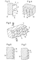
- the figures show method steps for producing anchoring surfaces 3 on metallic joint implants, which are at an angle 0 ⁇ ⁇ 90 degrees against the insertion and fastening direction 40 and have cup-shaped shoulder sections 14 which are open for anchoring against the insertion and fastening direction 40.
- cuts 6 and shoulders 8 are made in the anchoring surfaces 3 of a blank 2 by cutting, casting or eating Insertion and attachment direction 40 generated.
- the shoulders 8 are acute-angled in cross-section, have a height 10 between 0.3 and 2 mm and a distance 31 which corresponds approximately to the amount of twice the height 10.
- trenches 15 are produced by the shoulders 8 with a pressing tool 13 which has mating surfaces to the anchoring surfaces 3, which are provided with projecting ribs 26 which are perpendicular to the mating surface and parallel to the direction of insertion and fastening 40 with their central planes .
- the edges 17 of the shoulder sections 14 deform and cup-like shapes 18 are opened for support, which are open against the direction of insertion and attachment 40.
- FIG. 1 and 2 show a finished outer hip joint shell, the shape of which was processed according to the manufacturing steps indicated in FIG. 8. It has a hemisphere-like inner contour 19 for receiving an inner shell, not shown here, which snaps into the equator 32 with a snap connection.
- a center hole 30 with an internal thread for an impact tool is located in the pole axis 4 at the pole 33.
- Six longitudinal grooves 29 are distributed over the circumference, which serve as additional rotation lock when anchoring the outer shell. According to FIG. 8, these longitudinal slots can be made with a deep-drawing tool 13d in a preliminary step V2.
- the structure of the actual anchoring surface 3 results from recesses 6 and protruding shoulders 8, which are arranged transversely to the direction of insertion and fastening at certain latitudes.
- a deep-drawing tool 13f with ribs projecting in the direction of the meridians Trenches 15 have been pressed in, leaving only shoulder sections 14 of shoulders 8.
- FIG. 3 shows the geometry of the recesses 6 and the shoulders 8 produced in a processing step I on a shell blank 2c.
- the shoulders 8 have an acute-angled triangular cross section 9 and have a distance 31 between two adjacent tips 11, 12 which corresponds to approximately twice the amount of their height 10.
- the height 10 is chosen between 0.3 and 2 mm.
- a typical value for height 10 is 1 mm.
- the shape of the ribs 16 on a deep-drawing tool 13f is visible from FIG.
- the ribs 16 have the shape of a saddle roof 26, the ridge of which is rounded and are perpendicular to a base surface 36 with their central plane, the central planes running parallel to the direction of insertion and attachment 40.
- These ribs produce, by plastic deformation, the trenches 15 visible in FIG. 5, which divide the shoulders into shoulder sections 14. Since the deep-drawing tool moves against the anchoring surface 3 against the direction of insertion and fastening, the shoulder edges 17 of the shoulder sections 14 are pulled down, so that 40 cup shapes 18 are created against the direction of insertion and fastening.
- 6 and 7 show, on a section of a shell blank 2d, shoulder edges 17 drawn down to different degrees.
- the geometry of the cup shape 18 can be controlled by changing the shoulders 8 and the ribs 16. Furthermore, the smaller the angles ⁇ of the anchoring surface 3 to the direction of insertion and fastening 40, the further the shoulder edges 17 are pulled down. In the case of the outer hip joint shell in FIG. 1, this means that the typical cup shapes 18 are formed there in a pronounced manner, where they are most needed against undressing, namely towards equator 32.
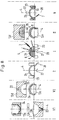
- FIG. 8 shows a work sequence for shaping an outer hip joint shell without taking heat treatments that may be in between into account.
- a rondelle 1 made of titanium sheet is inserted into a deep-drawing mold 13b, fixed with a hold-down device 24 and drawn by a tool punch 13a into a shell, which is ejected in the direction of the polar axis 4 using an ejector 22.
- this shell blank is placed on a support body 13c and optionally receives additional longitudinal grooves 29 with a deep-drawing tool 13d, which is provided with bumps 25 in the longitudinal direction, for later securing against rotation in the bone bed.
- receiving surfaces are turned on in the area of the equator. A direction of rotation 27, an axis of rotation 28, a clamping tool 23 and a turning tool 7 are only indicated symbolically.
- a shell blank 2b is clamped on its receiving surfaces on the equator with a clamping tool 23 and provided with recesses 6 on the anchoring surface.
- the axis of rotation 28 in the direction of the polar axis 4, the direction of rotation 27 and the turning tool 7 are indicated symbolically.
- the geometry of the recesses 6 and the shoulders 8 has already been described previously.
- the turning tool 7 is pivoted here about the ball center 5 of the outer shell.
- shaped steels can also be used on different widths of the spherical shell.
- a shell blank 2c prepared in this way which has shoulders transversely to the insertion and fastening direction 40, is placed on a support body 13e in a deep-drawing tool and in a process step II with a deep-drawing mold 13f, which has a hemispherical shape with ribs 26 protruding in the meridians his shoulders 8 deformed.
- the ribs 26, which strike against the direction of insertion and fastening, produce the trenches 15 shown in FIG. 5 and the shoulder sections 14 with the cup shape 18.
- the shell blank 2d is picked up on its receiving surfaces on the equator with a clamping tool 23, around the inner contour 19 ready to shoot.
- the axis of rotation 28 in the direction of the polar axis 4, the turning tool 7 and the direction of rotation 27 are only indicated symbolically.
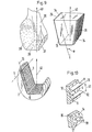
- surfaces 37, 38, 39 have been produced on a femoral stump by resection, on which the anchoring surfaces 3 of an upper part of a knee joint shown as blank 2 are intended to engage in an insertion and fastening direction 40.
- An associated pressing tool 13 has base surfaces 34 which correspond to the resection surfaces 37, 38, 39 and have the ribs 26 which run with their central plane perpendicular to the base surface 34 and parallel to the direction of insertion and attachment 40.
- 2 punctures 6 are made on the blank, the shoulders 8 are left standing.
- the shoulders 8 are shown enlarged with a puncture 6.
- the shoulder height 10 is between 0.3 and 2 mm while the distance 31 between the shoulder tips 11, 12 corresponds approximately to twice the amount of the shoulder height 10.
- the cross section of the shoulders 8 corresponds to an acute-angled triangular cross section 9.
- trenches 15 are formed in the anchoring surfaces 3, which divide the shoulders 8 into shoulder sections 14 as shown in the lower part of FIG. 10 and pull the shoulder edges 17 down against the direction of insertion and fastening 40 and produce cup shapes 18.
Landscapes
- Health & Medical Sciences (AREA)
- Engineering & Computer Science (AREA)
- Orthopedic Medicine & Surgery (AREA)
- Vascular Medicine (AREA)
- Animal Behavior & Ethology (AREA)
- Oral & Maxillofacial Surgery (AREA)
- Biomedical Technology (AREA)
- Heart & Thoracic Surgery (AREA)
- Cardiology (AREA)
- Life Sciences & Earth Sciences (AREA)
- Transplantation (AREA)
- General Health & Medical Sciences (AREA)
- Public Health (AREA)
- Veterinary Medicine (AREA)
- Mechanical Engineering (AREA)
- Prostheses (AREA)
- Joining Of Building Structures In Genera (AREA)
- Curing Cements, Concrete, And Artificial Stone (AREA)
Priority Applications (7)
| Application Number | Priority Date | Filing Date | Title |
|---|---|---|---|
| DE59310070T DE59310070D1 (de) | 1993-08-18 | 1993-08-18 | Verfahren zur Erzeugung von äusseren Verankerungsflächen an Gelenkimplantaten |
| AT93810583T ATE194274T1 (de) | 1993-08-18 | 1993-08-18 | Verfahren zur erzeugung von äusseren verankerungsflächen an gelenkimplantaten |
| ES93810583T ES2149194T3 (es) | 1993-08-18 | 1993-08-18 | Procedimiento para formar superficies de anclaje en saliente sobre implantes de articulaciones. |
| EP93810583A EP0639356B1 (fr) | 1993-08-18 | 1993-08-18 | Procédé pour former des surfaces d'ancrage en saillie sur des implants d'articulations |
| JP11910194A JP3529157B2 (ja) | 1993-08-18 | 1994-05-31 | 関節移植組織の外部取付面の製造方法 |
| US08/258,629 US5553476A (en) | 1993-08-18 | 1994-06-10 | Process for the production of outer attachment faces on joint implants |
| US08/684,111 US5755799A (en) | 1993-08-18 | 1996-07-19 | Joint implant with self-engaging attachment surface |
Applications Claiming Priority (1)
| Application Number | Priority Date | Filing Date | Title |
|---|---|---|---|
| EP93810583A EP0639356B1 (fr) | 1993-08-18 | 1993-08-18 | Procédé pour former des surfaces d'ancrage en saillie sur des implants d'articulations |
Publications (2)
| Publication Number | Publication Date |
|---|---|
| EP0639356A1 true EP0639356A1 (fr) | 1995-02-22 |
| EP0639356B1 EP0639356B1 (fr) | 2000-07-05 |
Family
ID=8215014
Family Applications (1)
| Application Number | Title | Priority Date | Filing Date |
|---|---|---|---|
| EP93810583A Expired - Lifetime EP0639356B1 (fr) | 1993-08-18 | 1993-08-18 | Procédé pour former des surfaces d'ancrage en saillie sur des implants d'articulations |
Country Status (6)
| Country | Link |
|---|---|
| US (2) | US5553476A (fr) |
| EP (1) | EP0639356B1 (fr) |
| JP (1) | JP3529157B2 (fr) |
| AT (1) | ATE194274T1 (fr) |
| DE (1) | DE59310070D1 (fr) |
| ES (1) | ES2149194T3 (fr) |
Cited By (9)
| Publication number | Priority date | Publication date | Assignee | Title |
|---|---|---|---|---|
| EP0867159A1 (fr) * | 1997-03-25 | 1998-09-30 | Sulzer Orthopädie AG | Coque acétabulaire artificielle à deux coques pour l'articulation de la hanche et sa fabrication |
| WO1999013700A3 (fr) * | 1999-01-12 | 1999-11-25 | Lipat Consulting Ag | Structure superficielle pour implant intraosseux |
| WO2009022911A3 (fr) * | 2007-08-16 | 2009-06-11 | Cam Implants Bv | Prothèse comprenant une surface d'interface osseuse anti-micromouvement, et son procédé de fabrication |
| US7799087B2 (en) | 2005-08-31 | 2010-09-21 | Zimmer Gmbh | Implant |
| EP2338443A1 (fr) * | 2009-12-23 | 2011-06-29 | Atesos medical AG | Cotyle d'articulation de la hanche artificielle destinée à l'ancrage non cimenté |
| WO2012113690A2 (fr) | 2011-02-22 | 2012-08-30 | Jossi Holding Ag | Procédé de production d'un implant présentant au moins une zone comportant une structure de surface, implant produit selon ledit procédé, et dispositif permettant la mise en œuvre dudit procédé |
| US8308807B2 (en) | 2005-11-09 | 2012-11-13 | Zimmer, Gmbh | Implant with differential anchoring |
| US8632601B2 (en) | 2006-04-28 | 2014-01-21 | Zimmer, Gmbh | Implant |
| US8979935B2 (en) | 2007-07-31 | 2015-03-17 | Zimmer, Inc. | Joint space interpositional prosthetic device with internal bearing surfaces |
Families Citing this family (46)
| Publication number | Priority date | Publication date | Assignee | Title |
|---|---|---|---|---|
| ES2180015T3 (es) * | 1996-04-10 | 2003-02-01 | Sulzer Orthopaedie Ag | Implante metalico que comprende una superficie y procedimiento para fabricar la superficie. |
| DE19780331D2 (de) * | 1996-04-22 | 1999-04-29 | Gerd Hoermansdoerfer | Hüftgelenkpfanne mit Spezialgewinde |
| CA2224478C (fr) * | 1996-05-14 | 2004-04-06 | Bruno Balay | Implant cotyloidien fixe sans ciment |
| US7255712B1 (en) | 1997-04-15 | 2007-08-14 | Active Implants Corporation | Bone growth promoting implant |
| US6180171B1 (en) * | 1997-08-29 | 2001-01-30 | Sintokogio, Ltd. | Method of producing a plated product having recesses |
| US5927136A (en) * | 1997-11-06 | 1999-07-27 | Reynolds; David L. | Method of treating a tubular member |
| US6139582A (en) * | 1997-11-21 | 2000-10-31 | Depuy Orthopaedics, Inc. | Acetabular cup with bi-directional steps |
| DE19757799A1 (de) | 1997-12-29 | 1999-07-01 | Gerd Hoermansdoerfer | Verfahren zum Humpeldrehen und bevorzugte Anwendung des Verfahrens |
| US7115143B1 (en) | 1999-12-08 | 2006-10-03 | Sdgi Holdings, Inc. | Orthopedic implant surface configuration |
| US6827740B1 (en) | 1999-12-08 | 2004-12-07 | Gary K. Michelson | Spinal implant surface configuration |
| JP4452008B2 (ja) * | 2000-12-08 | 2010-04-21 | 住友金属工業株式会社 | 湾曲金属板の製造方法、及びゴルフクラブヘッド |
| US6599322B1 (en) * | 2001-01-25 | 2003-07-29 | Tecomet, Inc. | Method for producing undercut micro recesses in a surface, a surgical implant made thereby, and method for fixing an implant to bone |
| US7018418B2 (en) * | 2001-01-25 | 2006-03-28 | Tecomet, Inc. | Textured surface having undercut micro recesses in a surface |
| DE10106863C2 (de) | 2001-02-14 | 2003-04-03 | Hans Ulrich Staeubli | Implantierbare Pfanne für Hüftgelenk-Endoprothesen |
| US7018417B2 (en) | 2001-07-31 | 2006-03-28 | Xaver Kuoni | Artificial socket |
| ES2337886T3 (es) | 2001-12-04 | 2010-04-30 | Active Implants Corporation | Implantes que llevan una almohadilla para aplicaciones de soporte de carga. |
| AU2003228083A1 (en) * | 2002-05-23 | 2003-12-12 | Discure, Ltd. | Joint and dental implants |
| US20040243134A1 (en) * | 2003-05-30 | 2004-12-02 | Walker Peter Stanley | Bone shaping device for knee replacement |
| EP1498090A1 (fr) * | 2003-07-16 | 2005-01-19 | WALDEMAR LINK GmbH & Co. KG | Prothèse de hanche avec une tige fémorale |
| US7080539B2 (en) | 2003-12-22 | 2006-07-25 | Federal-Mogul World Wide, Inc. | Forged knurled socket housing and method of manufacture |
| US8140489B2 (en) * | 2004-03-24 | 2012-03-20 | Oracle International Corporation | System and method for analyzing content on a web page using an embedded filter |
| US20090048679A1 (en) * | 2006-02-09 | 2009-02-19 | Zimmer Gmbh | Implant |
| FR2915089B1 (fr) * | 2007-04-18 | 2011-10-21 | Cadorel Catherine | Dispositif et procede de creation d'une plaque d'osteo-integration a la surface d'un implant endo-osseux |
| FR2915088B1 (fr) * | 2007-04-18 | 2010-03-12 | Cadorel Catherine | Implant endo-osseux composite a accrochage mecanique optimise et procede de fabrication d'un tel implant. |
| US7780740B2 (en) * | 2007-05-21 | 2010-08-24 | Active Implants Corporation | Methods, systems, and apparatus for implanting prosthetic devices into cartilage |
| DE202007008430U1 (de) * | 2007-06-15 | 2008-10-16 | Heise, Sebastian | Beleuchtungsvorrichtung |
| US8764837B2 (en) * | 2008-03-26 | 2014-07-01 | Linares Medical Devices, Llc | Reinforced joint assembly |
| WO2009108960A2 (fr) * | 2008-02-25 | 2009-09-03 | Linares Medical Devices, Llc | Bouchon artificiel anti-usure à monter sur une articulation osseuse existante |
| US8979938B2 (en) * | 2007-11-08 | 2015-03-17 | Linares Medical Devices, Llc | Artificial knee implant including liquid ballast supporting / rotating surfaces and incorporating flexible multi-material and natural lubricant retaining matrix applied to a joint surface |
| US8828088B2 (en) * | 2007-11-08 | 2014-09-09 | Linares Medical Devices, Llc | Joint assembly incorporating undercut surface design to entrap accumulating wear debris from plastic joint assembly |
| US9539097B2 (en) | 2007-11-08 | 2017-01-10 | Linares Medical Devices, Llc | Hip and knee joint assemblies incorporating debris collection architecture between the ball and seat interface |
| US8123815B2 (en) | 2008-11-24 | 2012-02-28 | Biomet Manufacturing Corp. | Multiple bearing acetabular prosthesis |
| US8308810B2 (en) | 2009-07-14 | 2012-11-13 | Biomet Manufacturing Corp. | Multiple bearing acetabular prosthesis |
| US8556901B2 (en) | 2009-12-31 | 2013-10-15 | DePuy Synthes Products, LLC | Reciprocating rasps for use in an orthopaedic surgical procedure |
| US8506569B2 (en) | 2009-12-31 | 2013-08-13 | DePuy Synthes Products, LLC | Reciprocating rasps for use in an orthopaedic surgical procedure |
| US8926705B2 (en) | 2010-05-10 | 2015-01-06 | Linares Medical Devices, Llc | Implantable joint assembly featuring debris entrapment chamber subassemblies along with opposing magnetic fields generated between articulating implant components in order to minimize frictional force and associated wear |
| US8486076B2 (en) | 2011-01-28 | 2013-07-16 | DePuy Synthes Products, LLC | Oscillating rasp for use in an orthopaedic surgical procedure |
| US9023112B2 (en) * | 2011-02-24 | 2015-05-05 | Depuy (Ireland) | Maintaining proper mechanics THA |
| EP2502604B1 (fr) * | 2011-03-21 | 2013-09-25 | Jossi Holding AG | Implant de poêle articulée |
| US9668745B2 (en) | 2011-12-19 | 2017-06-06 | Depuy Ireland Unlimited Company | Anatomical concentric spheres THA |
| US8858645B2 (en) | 2012-06-21 | 2014-10-14 | DePuy Synthes Products, LLC | Constrained mobile bearing hip assembly |
| US9427322B1 (en) * | 2012-06-27 | 2016-08-30 | Signal Medical Corporation | Hip implant |
| GB2547907A (en) * | 2016-03-02 | 2017-09-06 | Invibio Knees Ltd | Prosthesis |
| GB2547908A (en) * | 2016-03-02 | 2017-09-06 | Invibio Knees Ltd | Replacement knee component |
| JP2023523068A (ja) * | 2020-04-30 | 2023-06-01 | オーストラリアン インスティテュート オブ ロボティック オーソピーディクス プロプライエタリー リミテッド | 整形外科インプラントおよびそれを組み込む外科手術用整形外科システム |
| US12048442B2 (en) * | 2022-01-06 | 2024-07-30 | DePuy Synthes Products, Inc. | Femoral finishing rasp |
Citations (4)
| Publication number | Priority date | Publication date | Assignee | Title |
|---|---|---|---|---|
| EP0108729A1 (fr) * | 1982-11-04 | 1984-05-16 | Alberto Scoti | Procédé pour fabriquer des surfaces agrandies d'échangeur thermique et outil approprié |
| EP0169978A1 (fr) * | 1984-07-16 | 1986-02-05 | GebràDer Sulzer Aktiengesellschaft | Endoprothèse cotyloidiènne munie d'une partie intérieure et d'une partie extérieure |
| EP0186471A2 (fr) * | 1984-12-20 | 1986-07-02 | Chas F Thackray Limited | Prothèse du genou |
| US4865603A (en) * | 1988-02-04 | 1989-09-12 | Joint Medical Products Corporation | Metallic prosthetic devices having micro-textured outer surfaces |
Family Cites Families (16)
| Publication number | Priority date | Publication date | Assignee | Title |
|---|---|---|---|---|
| US3487670A (en) * | 1965-03-29 | 1970-01-06 | Trane Co | Method of forming indentations in fins extending from a heat transfer surface |
| DE2320747A1 (de) * | 1973-04-25 | 1974-11-21 | Muelheimer Gitterrostfabrik Gm | Verfahren zur herstellung von gitterrosten |
| FR2272637B2 (fr) * | 1974-05-29 | 1977-09-30 | Ceraver | |
| US4194384A (en) * | 1975-01-13 | 1980-03-25 | Hitachi, Ltd. | Method of manufacturing heat-transfer wall for vapor condensation |
| CH630251A5 (de) * | 1978-05-19 | 1982-06-15 | Sulzer Ag | Oberflaechenstruktur an verankerungselement eines knochenimplantates. |
| CH649913A5 (en) * | 1981-03-19 | 1985-06-28 | Sulzer Ag | Cementlessly anchorable joint socket |
| GB2127327B (en) * | 1982-08-20 | 1986-04-30 | Alton Systems Limited | An antiskid surface treatment for use on scaffolding components |
| US4662891A (en) * | 1983-11-21 | 1987-05-05 | Joint Medical Products Corporation | Fixation elements for artificial joints |
| DE8431422U1 (de) * | 1984-10-23 | 1985-11-21 | Mecron Medizinische Produkte Gmbh, 1000 Berlin | Trägerelement |
| CA1290099C (fr) * | 1986-01-21 | 1991-10-08 | Thomas H. Mallory | Articulation artificielle a revetement poreux |
| FR2595562B1 (fr) * | 1986-03-13 | 1992-08-28 | Rhenter Jean Luc | Cupule de prothese |
| FR2620932A1 (fr) * | 1987-09-28 | 1989-03-31 | Saffar Philippe | Prothese d'articulation metacarpo-phalangienne ou interphalangienne de doigts |
| CH674708A5 (fr) * | 1988-04-11 | 1990-07-13 | Sulzer Ag | |
| US5108446A (en) * | 1990-11-26 | 1992-04-28 | Sulzer Brothers Limited | Hip joint prosthesis |
| JPH0549656A (ja) * | 1991-06-24 | 1993-03-02 | Sumitomo Metal Ind Ltd | 耐摩耗性に優れたチタン合金製人工関節 |
| US5358532A (en) * | 1992-06-16 | 1994-10-25 | Smith & Nephew Richards Inc. | Cementless acetabular cup |
-
1993
- 1993-08-18 AT AT93810583T patent/ATE194274T1/de not_active IP Right Cessation
- 1993-08-18 DE DE59310070T patent/DE59310070D1/de not_active Expired - Lifetime
- 1993-08-18 ES ES93810583T patent/ES2149194T3/es not_active Expired - Lifetime
- 1993-08-18 EP EP93810583A patent/EP0639356B1/fr not_active Expired - Lifetime
-
1994
- 1994-05-31 JP JP11910194A patent/JP3529157B2/ja not_active Expired - Fee Related
- 1994-06-10 US US08/258,629 patent/US5553476A/en not_active Expired - Lifetime
-
1996
- 1996-07-19 US US08/684,111 patent/US5755799A/en not_active Expired - Lifetime
Patent Citations (4)
| Publication number | Priority date | Publication date | Assignee | Title |
|---|---|---|---|---|
| EP0108729A1 (fr) * | 1982-11-04 | 1984-05-16 | Alberto Scoti | Procédé pour fabriquer des surfaces agrandies d'échangeur thermique et outil approprié |
| EP0169978A1 (fr) * | 1984-07-16 | 1986-02-05 | GebràDer Sulzer Aktiengesellschaft | Endoprothèse cotyloidiènne munie d'une partie intérieure et d'une partie extérieure |
| EP0186471A2 (fr) * | 1984-12-20 | 1986-07-02 | Chas F Thackray Limited | Prothèse du genou |
| US4865603A (en) * | 1988-02-04 | 1989-09-12 | Joint Medical Products Corporation | Metallic prosthetic devices having micro-textured outer surfaces |
Cited By (13)
| Publication number | Priority date | Publication date | Assignee | Title |
|---|---|---|---|---|
| EP0867159A1 (fr) * | 1997-03-25 | 1998-09-30 | Sulzer Orthopädie AG | Coque acétabulaire artificielle à deux coques pour l'articulation de la hanche et sa fabrication |
| WO1999013700A3 (fr) * | 1999-01-12 | 1999-11-25 | Lipat Consulting Ag | Structure superficielle pour implant intraosseux |
| US6554867B1 (en) | 1999-01-12 | 2003-04-29 | Lipat Consulting Ag | Surface structure for intraosseous implant |
| US7799087B2 (en) | 2005-08-31 | 2010-09-21 | Zimmer Gmbh | Implant |
| US8394149B2 (en) | 2005-08-31 | 2013-03-12 | Zimmer, Gmbh | Method for implantation of a femoral implant |
| US8308807B2 (en) | 2005-11-09 | 2012-11-13 | Zimmer, Gmbh | Implant with differential anchoring |
| US8632601B2 (en) | 2006-04-28 | 2014-01-21 | Zimmer, Gmbh | Implant |
| US8979935B2 (en) | 2007-07-31 | 2015-03-17 | Zimmer, Inc. | Joint space interpositional prosthetic device with internal bearing surfaces |
| WO2009022911A3 (fr) * | 2007-08-16 | 2009-06-11 | Cam Implants Bv | Prothèse comprenant une surface d'interface osseuse anti-micromouvement, et son procédé de fabrication |
| EP2338443A1 (fr) * | 2009-12-23 | 2011-06-29 | Atesos medical AG | Cotyle d'articulation de la hanche artificielle destinée à l'ancrage non cimenté |
| WO2012113690A3 (fr) * | 2011-02-22 | 2012-10-26 | Jossi Holding Ag | Procédé de production d'un implant présentant au moins une zone comportant une structure de surface, implant produit selon ledit procédé, et dispositif permettant la mise en œuvre dudit procédé |
| CH704518A1 (de) * | 2011-02-22 | 2012-08-31 | Jossi Holding Ag | Verfahren zur Herstellung eines Implantats mit mindestens einem Bereich mit einer Oberflächenstruktur, nach dem Verfahren hergestelltes Implantat und Vorrichtung zur Durchführung des Verfahrens. |
| WO2012113690A2 (fr) | 2011-02-22 | 2012-08-30 | Jossi Holding Ag | Procédé de production d'un implant présentant au moins une zone comportant une structure de surface, implant produit selon ledit procédé, et dispositif permettant la mise en œuvre dudit procédé |
Also Published As
| Publication number | Publication date |
|---|---|
| EP0639356B1 (fr) | 2000-07-05 |
| DE59310070D1 (de) | 2000-08-10 |
| ES2149194T3 (es) | 2000-11-01 |
| ATE194274T1 (de) | 2000-07-15 |
| US5553476A (en) | 1996-09-10 |
| JP3529157B2 (ja) | 2004-05-24 |
| JPH0759803A (ja) | 1995-03-07 |
| US5755799A (en) | 1998-05-26 |
Similar Documents
| Publication | Publication Date | Title |
|---|---|---|
| EP0639356B1 (fr) | Procédé pour former des surfaces d'ancrage en saillie sur des implants d'articulations | |
| DE3781163T2 (de) | Manschette zum befestigen kuenstlicher gelenke an knochen. | |
| EP0656199B1 (fr) | Coque acétabulaire sphérique pour l'articulation de la hanche | |
| EP0289922B1 (fr) | Prothèse d'articulation et procédé pour sa fabrication | |
| EP0699425B1 (fr) | Coque acétabulaire artificielle pour l'articulation de la hanche ainsi que procédé de fabrication | |
| EP0169978B1 (fr) | Endoprothèse cotyloidiènne munie d'une partie intérieure et d'une partie extérieure | |
| EP0159510B1 (fr) | Endoprothèse d'articulation de hanche | |
| EP0182176B1 (fr) | Procédé pour fabriquer des endoprothèses | |
| EP0489684B1 (fr) | Implant pour la construction de tissu osseux | |
| DE3310486C2 (de) | Endoprothesenschaft zum zementfreien Einsetzen in einen Knochenhohlraum | |
| EP1924208B1 (fr) | Implant du femur | |
| DE69529159T2 (de) | Hüftgelenkprothese | |
| EP0867159A1 (fr) | Coque acétabulaire artificielle à deux coques pour l'articulation de la hanche et sa fabrication | |
| EP0142759A2 (fr) | Cuvette d'articulation de la hanche | |
| EP3416594B1 (fr) | Implant pour la reconstruction d'une acétabule et de partie du bassin | |
| EP0522999B1 (fr) | Prothèse de rotule | |
| EP3714840B1 (fr) | Cavité cotyloïde d'une endoprothèse de l'articulation de la hanche | |
| EP0726066A2 (fr) | Cupule cotyloidienne implantable | |
| EP0303006A1 (fr) | Cupule acétabulaire pour une endoprothèse de la hanche | |
| EP0663193A1 (fr) | Coque acétabulaire artificielle pour la hanche | |
| DE3822154C2 (de) | Prothetisches Implantat mit einem porösen Kissen und Verfahren zu dessen Herstellung | |
| EP0368796B1 (fr) | Procédé de fabrication d'une prothèse munie d'une tige | |
| DE2454635A1 (de) | Kuenstliches hueftgelenk | |
| DE69514110T2 (de) | Endoprothese | |
| EP1326551A1 (fr) | Implant presentant une structure rainuree |
Legal Events
| Date | Code | Title | Description |
|---|---|---|---|
| PUAI | Public reference made under article 153(3) epc to a published international application that has entered the european phase |
Free format text: ORIGINAL CODE: 0009012 |
|
| AK | Designated contracting states |
Kind code of ref document: A1 Designated state(s): AT BE CH DE ES FR GB IT LI NL SE |
|
| 17P | Request for examination filed |
Effective date: 19950705 |
|
| 17Q | First examination report despatched |
Effective date: 19981210 |
|
| GRAG | Despatch of communication of intention to grant |
Free format text: ORIGINAL CODE: EPIDOS AGRA |
|
| RAP1 | Party data changed (applicant data changed or rights of an application transferred) |
Owner name: SULZER ORTHOPAEDIE AG |
|
| GRAG | Despatch of communication of intention to grant |
Free format text: ORIGINAL CODE: EPIDOS AGRA |
|
| GRAH | Despatch of communication of intention to grant a patent |
Free format text: ORIGINAL CODE: EPIDOS IGRA |
|
| GRAH | Despatch of communication of intention to grant a patent |
Free format text: ORIGINAL CODE: EPIDOS IGRA |
|
| GRAA | (expected) grant |
Free format text: ORIGINAL CODE: 0009210 |
|
| AK | Designated contracting states |
Kind code of ref document: B1 Designated state(s): AT BE CH DE ES FR GB IT LI NL SE |
|
| REF | Corresponds to: |
Ref document number: 194274 Country of ref document: AT Date of ref document: 20000715 Kind code of ref document: T |
|
| REG | Reference to a national code |
Ref country code: CH Ref legal event code: NV Representative=s name: SULZER MANAGEMENT AG Ref country code: CH Ref legal event code: EP |
|
| GBT | Gb: translation of ep patent filed (gb section 77(6)(a)/1977) |
Effective date: 20000705 |
|
| REF | Corresponds to: |
Ref document number: 59310070 Country of ref document: DE Date of ref document: 20000810 |
|
| ITF | It: translation for a ep patent filed | ||
| ET | Fr: translation filed | ||
| REG | Reference to a national code |
Ref country code: ES Ref legal event code: FG2A Ref document number: 2149194 Country of ref document: ES Kind code of ref document: T3 |
|
| PLBE | No opposition filed within time limit |
Free format text: ORIGINAL CODE: 0009261 |
|
| STAA | Information on the status of an ep patent application or granted ep patent |
Free format text: STATUS: NO OPPOSITION FILED WITHIN TIME LIMIT |
|
| 26N | No opposition filed | ||
| REG | Reference to a national code |
Ref country code: GB Ref legal event code: IF02 |
|
| REG | Reference to a national code |
Ref country code: CH Ref legal event code: PUE Owner name: ZIMMER GMBH Free format text: SULZER ORTHOPAEDIE AG#GRABENSTRASSE 25#6340 BAAR (CH) -TRANSFER TO- ZIMMER GMBH#SULZER ALLEE 8#8404 WINTERTHUR (CH) |
|
| NLS | Nl: assignments of ep-patents |
Owner name: ZIMMER GMBH Effective date: 20061010 |
|
| NLT1 | Nl: modifications of names registered in virtue of documents presented to the patent office pursuant to art. 16 a, paragraph 1 |
Owner name: CENTERPULSE ORTHOPEDICS LTD. |
|
| REG | Reference to a national code |
Ref country code: FR Ref legal event code: TP Ref country code: FR Ref legal event code: CD Ref country code: FR Ref legal event code: CA |
|
| BECA | Be: change of holder's address |
Owner name: *ZIMMER G.M.B.H.SULZER ALLEE 8, CH-8404 WINTERTHUR Effective date: 20060802 |
|
| BECH | Be: change of holder |
Owner name: *ZIMMER G.M.B.H. Effective date: 20060802 |
|
| BECN | Be: change of holder's name |
Owner name: *ZIMMER G.M.B.H.SULZER ALLEE 8, CH-8404 WINTERTHUR Effective date: 20060802 Owner name: *ZIMMER G.M.B.H. Effective date: 20060802 |
|
| PGFP | Annual fee paid to national office [announced via postgrant information from national office to epo] |
Ref country code: NL Payment date: 20080813 Year of fee payment: 16 |
|
| PGFP | Annual fee paid to national office [announced via postgrant information from national office to epo] |
Ref country code: AT Payment date: 20080814 Year of fee payment: 16 |
|
| REG | Reference to a national code |
Ref country code: GB Ref legal event code: 732E Free format text: REGISTERED BETWEEN 20100121 AND 20100127 |
|
| REG | Reference to a national code |
Ref country code: NL Ref legal event code: V1 Effective date: 20100301 |
|
| PG25 | Lapsed in a contracting state [announced via postgrant information from national office to epo] |
Ref country code: AT Free format text: LAPSE BECAUSE OF NON-PAYMENT OF DUE FEES Effective date: 20090818 |
|
| PG25 | Lapsed in a contracting state [announced via postgrant information from national office to epo] |
Ref country code: NL Free format text: LAPSE BECAUSE OF NON-PAYMENT OF DUE FEES Effective date: 20100301 |
|
| PGFP | Annual fee paid to national office [announced via postgrant information from national office to epo] |
Ref country code: CH Payment date: 20110824 Year of fee payment: 19 |
|
| PGFP | Annual fee paid to national office [announced via postgrant information from national office to epo] |
Ref country code: SE Payment date: 20110824 Year of fee payment: 19 Ref country code: ES Payment date: 20110825 Year of fee payment: 19 |
|
| PGFP | Annual fee paid to national office [announced via postgrant information from national office to epo] |
Ref country code: GB Payment date: 20120821 Year of fee payment: 20 |
|
| PGFP | Annual fee paid to national office [announced via postgrant information from national office to epo] |
Ref country code: BE Payment date: 20120824 Year of fee payment: 20 Ref country code: DE Payment date: 20120822 Year of fee payment: 20 Ref country code: IT Payment date: 20120822 Year of fee payment: 20 Ref country code: FR Payment date: 20120906 Year of fee payment: 20 |
|
| REG | Reference to a national code |
Ref country code: SE Ref legal event code: EUG |
|
| PG25 | Lapsed in a contracting state [announced via postgrant information from national office to epo] |
Ref country code: SE Free format text: LAPSE BECAUSE OF NON-PAYMENT OF DUE FEES Effective date: 20120819 |
|
| REG | Reference to a national code |
Ref country code: DE Ref legal event code: R071 Ref document number: 59310070 Country of ref document: DE |
|
| REG | Reference to a national code |
Ref country code: CH Ref legal event code: PL |
|
| BE20 | Be: patent expired |
Owner name: *ZIMMER G.M.B.H. Effective date: 20130818 |
|
| REG | Reference to a national code |
Ref country code: GB Ref legal event code: PE20 Expiry date: 20130817 |
|
| REG | Reference to a national code |
Ref country code: ES Ref legal event code: FD2A Effective date: 20131018 |
|
| PG25 | Lapsed in a contracting state [announced via postgrant information from national office to epo] |
Ref country code: DE Free format text: LAPSE BECAUSE OF EXPIRATION OF PROTECTION Effective date: 20130820 Ref country code: ES Free format text: LAPSE BECAUSE OF NON-PAYMENT OF DUE FEES Effective date: 20120819 |
|
| PG25 | Lapsed in a contracting state [announced via postgrant information from national office to epo] |
Ref country code: GB Free format text: LAPSE BECAUSE OF EXPIRATION OF PROTECTION Effective date: 20130817 |