EP0640417A1 - Outil supérieur pour une presse - Google Patents
Outil supérieur pour une presse Download PDFInfo
- Publication number
- EP0640417A1 EP0640417A1 EP19930401983 EP93401983A EP0640417A1 EP 0640417 A1 EP0640417 A1 EP 0640417A1 EP 19930401983 EP19930401983 EP 19930401983 EP 93401983 A EP93401983 A EP 93401983A EP 0640417 A1 EP0640417 A1 EP 0640417A1
- Authority
- EP
- European Patent Office
- Prior art keywords
- punch guide
- damping member
- stripper plate
- shock damping
- upper tool
- Prior art date
- Legal status (The legal status is an assumption and is not a legal conclusion. Google has not performed a legal analysis and makes no representation as to the accuracy of the status listed.)
- Granted
Links
- 230000035939 shock Effects 0.000 claims abstract description 48
- 238000013016 damping Methods 0.000 claims abstract description 45
- JOYRKODLDBILNP-UHFFFAOYSA-N Ethyl urethane Chemical compound CCOC(N)=O JOYRKODLDBILNP-UHFFFAOYSA-N 0.000 claims description 3
- 238000004080 punching Methods 0.000 abstract description 14
- 238000000034 method Methods 0.000 abstract description 12
- 239000000463 material Substances 0.000 description 7
- 239000002184 metal Substances 0.000 description 3
- 229920006311 Urethane elastomer Polymers 0.000 description 2
- 239000013013 elastic material Substances 0.000 description 2
- 229920002379 silicone rubber Polymers 0.000 description 2
- 239000004945 silicone rubber Substances 0.000 description 2
- 238000010276 construction Methods 0.000 description 1
- 230000002542 deteriorative effect Effects 0.000 description 1
- 230000000694 effects Effects 0.000 description 1
Images


Classifications
-
- B—PERFORMING OPERATIONS; TRANSPORTING
- B21—MECHANICAL METAL-WORKING WITHOUT ESSENTIALLY REMOVING MATERIAL; PUNCHING METAL
- B21D—WORKING OR PROCESSING OF SHEET METAL OR METAL TUBES, RODS OR PROFILES WITHOUT ESSENTIALLY REMOVING MATERIAL; PUNCHING METAL
- B21D45/00—Ejecting or stripping-off devices arranged in machines or tools dealt with in this subclass
- B21D45/003—Ejecting or stripping-off devices arranged in machines or tools dealt with in this subclass in punching machines or punching tools
- B21D45/006—Stripping-off devices
-
- B—PERFORMING OPERATIONS; TRANSPORTING
- B26—HAND CUTTING TOOLS; CUTTING; SEVERING
- B26D—CUTTING; DETAILS COMMON TO MACHINES FOR PERFORATING, PUNCHING, CUTTING-OUT, STAMPING-OUT OR SEVERING
- B26D7/00—Details of apparatus for cutting, cutting-out, stamping-out, punching, perforating, or severing by means other than cutting
- B26D7/18—Means for removing cut-out material or waste
- B26D7/1818—Means for removing cut-out material or waste by pushing out
-
- Y—GENERAL TAGGING OF NEW TECHNOLOGICAL DEVELOPMENTS; GENERAL TAGGING OF CROSS-SECTIONAL TECHNOLOGIES SPANNING OVER SEVERAL SECTIONS OF THE IPC; TECHNICAL SUBJECTS COVERED BY FORMER USPC CROSS-REFERENCE ART COLLECTIONS [XRACs] AND DIGESTS
- Y10—TECHNICAL SUBJECTS COVERED BY FORMER USPC
- Y10T—TECHNICAL SUBJECTS COVERED BY FORMER US CLASSIFICATION
- Y10T83/00—Cutting
- Y10T83/202—With product handling means
- Y10T83/2092—Means to move, guide, or permit free fall or flight of product
- Y10T83/2096—Means to move product out of contact with tool
- Y10T83/2135—Moving stripper timed with tool stroke
- Y10T83/215—Carried by moving tool element or its support
- Y10T83/2155—Stripper biased against product
- Y10T83/2159—By spring means
Definitions
- the present invention relates to an upper tool used to effect a press processing in a plate-shaped workpiece in cooperation with a lower tool.
- a punch is housed in a cylindrical punch guide so as to be movable up and down.
- the punch guide is formed of a metal, and a shock damping material, such as urethane, may be attached to the lower end surface of the punch guide.
- the shock damping material serves to reduce a noise generated during the punching process.
- shock damping material such as urethane
- the shock damping material such as urethane
- needle-shaped chips (refuse) produced during the punching process may adhere onto the shock damping material.
- the plate-material may be scratched by the needle-shaped chips adhered to the shock damping material.
- the present invention provides an upper tool wherein a stripper plate (35) is disposed at a lower end portion of a punch guide (13) via a shock damping member (33). Further, the shock damping member (33) is an annular body disposed so as to enclose an annular gap (X) formed between the lower end portion of the punch guide (13) and an upper end portion of the stripper plate (35).
- the stripper plate is disposed at the lower end portion of the punch guide via the shock damping member, whereby it is possible to reduce the noise generated when the stripper plate collides with the workpiece during the punching process. This is because a shock can be absorbed by the shock damping member.
- the width of the gap between the stripper plate and the punch guide is small, it is possible to prevent the shock damping member from being deformed excessively during the punching process and thereby to improve the life time of the shock damping member.
- a turret punch press 1 as an example of press machines, is provided with an upper turret 3 (upper tool holding member) and a lower turret 5 (lower tool holding member) both arranged in opposing positional relationship with respect to each other.
- An upper tool 7 is removably mounted on the upper turret 3
- a lower tool 9 is also removably mounted on the lower turret 5, respectively.
- the upper turret 3 is formed with an upper tool mounting hole 11.
- a cylindrical punch guide 13 is fitted into the upper tool mounting hole 11 so as to be movable up and down. Further, in order to prevent the punch guide 13 from rotating relative to the upper turret 3, the punch guide 13 is formed with an appropriate number of vertically extending key grooves 17, and the upper turret 3 is formed with an appropriate number of cutout portions 19 communicating with the upper tool mounting holes 11, respectively. Further, a lift spring 25 is interposed between an upper flange 23 of the punch guide 13 and the upper surface of the upper turret 13 to urge the punch guide 13 upward.
- a punch 27 is fitted into a through hole 15 of the punch guide 13 so as to be movable up and down.
- the punch 27 is reduced gradually in diameter at the lower end portion of the punch 27 so as to form a processing section.
- the punch 27 is provided with a punch head 29 at the upper end portion thereof.
- a stripper spring 31 is interposed between the punch head 29 and the flange 23 of the punch guide 13 to urge the punch 27 upward.
- the spring constant of this stripper spring 31 is determined to be bigger than that of the lift spring 25.
- a stripper plate 35 is attached to the lower end surface of the punch guide 13 via a shock damping member 33 formed of an elastic material such as urethane rubber, silicone rubber, etc.
- the lower turret 5 is formed with a lower tool mounting hole 37 in opposing positional relationship with respect to the upper tool mounting hole 11.
- a lower tool 41 formed with a hole 39 is fitted into this lower tool mounting hole 37.
- the lower tool 41 is formed with an appropriate number of vertically extending key grooves 43, and the lower turret 5 is formed with an appropriate number of cutout portions 45 communicating with the lower tool mounting holes 37, respectively.
- An appropriate number of keys 47 are provided horizontally so as to engage with the key grooves 43, respectively.
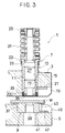
- the upper tool 7 including the punch guide 13, the shock damping member 33, and the stripper plate 35 will be described in more detail hereinbelow with reference to figures 1 and 2.
- the punch guide 13 is formed with an outer annular recessed groove portion 51 and immediately below said groove portion 51 with an outwardly projecting annular rib 49 for supporting the shock damping member 33 at the lower end portion 13a thereof.
- the shock damping member 33 is an annular-shaped member having an outer annular body portion 53 and two inwardly projecting annular rib portions 55 formed on the end parts of the inner cylindrical surface of the outer annular body portion 53.
- the shock damping member 33 is formed of an elastic material such as urethane rubber, silicone rubber, etc.
- the upper portion of the two inwardly projecting rib portions 55 of the shock damping member 33 is removably engaged in the outer annular recessed groove portion 51 of the punch guide 13.
- the stripper plate 35 made of a metal is a disk-shaped member formed with a central through hole 57 for allowing the punch 27 to pass therethrough.
- the stripper plate 35 is formed with an outwardly projecting annular rib portion 59 and immediately below said portion 59 with an inwardly recessed annular groove portion 61.
- the lower portion of the two inwardly projecting rib portions 55 of the shock damping member 33 is removably engaged in the outer annular recessed groove portion 61 of the stripper plate 35.
- a plurality of vertical stop pins 63 are inserted vertically into the punch guide 13 through the stripper plate 35 and the shock damping member 33 in order to prevent the rotation of the stripper plate 35 and of the shock damping member 33 relative to the punch guide 13 whereby the lower end of said stop pins 63 is spaced away upwardly from the lower face of said stripper plate 35 so as to permit the vertical deformation of the shock damping member 33 without the workpiece W being contacted by said stop pins 63.
- a vertical gap X between the stripper plate 35 and the shock damping member 33 by locating both rib portions 55 at a distance from each each other sufficient to space away the upper surface 65 of the stripper plate 35 from the lower surface 67 of the end portion 13a of the punch guide 13 at a given distance X.
- the height of the gap X is preferably about 1 mm, for instance, said gap X being located within the space surrounded by the middle part of the shock damping member 33 and extending from the inner cylindrical surface of said member 33 to the inner hole 57 of the stripper plate 35.
- the shock damping member 33 attached to the lower end of the punch guide 13 serves to damp the shock and therefore absorb noise thanks to the cushion function thereof.
- the vertical deformation of the shock damping member 33 is at the very most equal to the gap X (about 1 mm) since the upper surface 65 of the stripper plate 35 collides with the lower surface 67 of the punch guide 13 when the shock damping member 33 is deformed too excessively; thus, the shock damping member 33 is prevented from being deformed excessively and its life time is improved.
- the stripper plate 35 is provided with no shock damping member at its lower end surface, needle-shaped chips (refuse) produced during the punching process do not adhere to the stripper plate 35. Thus, the workpiece W is protected from being scratched by the chips.
- the above-mentioned shock damping member can be modified in shape and material without being limited to only the above-mentioned embodiment.
- the shock damping member is provided between the punch guide and the stripper plate, it is possible to prevent noisy sounds generated when the workpiece W is sandwiched between the upper tool and the lower tool during the punching process, thus improving the working environment. Further, since the needle-shaped chips produced during the punching process will not scratch the upper surface of the workpiece W and the shock damping member, it is possible to protect the workpiece from being scratched and further to improve the life time of the shock damping member.
Landscapes
- Engineering & Computer Science (AREA)
- Mechanical Engineering (AREA)
- Life Sciences & Earth Sciences (AREA)
- Forests & Forestry (AREA)
- Presses And Accessory Devices Thereof (AREA)
- Punching Or Piercing (AREA)
Priority Applications (4)
| Application Number | Priority Date | Filing Date | Title |
|---|---|---|---|
| US08/098,030 US5410926A (en) | 1993-07-28 | 1993-07-28 | Upper tool for a press |
| EP19930401983 EP0640417B1 (fr) | 1993-07-30 | 1993-07-30 | Outil supérieur pour une presse |
| DE69316003T DE69316003T2 (de) | 1993-07-30 | 1993-07-30 | Oberes Werkzeug für eine Presse |
| US08/352,123 US5553523A (en) | 1993-07-28 | 1994-12-01 | Upper tool for a press |
Applications Claiming Priority (2)
| Application Number | Priority Date | Filing Date | Title |
|---|---|---|---|
| EP19930401983 EP0640417B1 (fr) | 1993-07-30 | 1993-07-30 | Outil supérieur pour une presse |
| US08/352,123 US5553523A (en) | 1993-07-28 | 1994-12-01 | Upper tool for a press |
Publications (2)
| Publication Number | Publication Date |
|---|---|
| EP0640417A1 true EP0640417A1 (fr) | 1995-03-01 |
| EP0640417B1 EP0640417B1 (fr) | 1997-12-29 |
Family
ID=26134724
Family Applications (1)
| Application Number | Title | Priority Date | Filing Date |
|---|---|---|---|
| EP19930401983 Expired - Lifetime EP0640417B1 (fr) | 1993-07-28 | 1993-07-30 | Outil supérieur pour une presse |
Country Status (2)
| Country | Link |
|---|---|
| US (1) | US5553523A (fr) |
| EP (1) | EP0640417B1 (fr) |
Cited By (1)
| Publication number | Priority date | Publication date | Assignee | Title |
|---|---|---|---|---|
| EP0770437A1 (fr) * | 1995-10-26 | 1997-05-02 | Mate Precision Tooling GmbH | Outil d'emboutissage avec support pour platine d'arrachage |
Families Citing this family (3)
| Publication number | Priority date | Publication date | Assignee | Title |
|---|---|---|---|---|
| US5701790A (en) * | 1993-07-28 | 1997-12-30 | Amada Metrecs Company, Limited | Upper tool for a press |
| US6311594B1 (en) * | 1996-07-03 | 2001-11-06 | Amada Company, Limited | Punch guiding apparatus and stripper plate used therefor |
| JP7505857B2 (ja) * | 2018-08-02 | 2024-06-25 | トヨタ自動車株式会社 | 分断装置および分断方法 |
Citations (4)
| Publication number | Priority date | Publication date | Assignee | Title |
|---|---|---|---|---|
| FR1456310A (fr) * | 1964-12-02 | 1966-10-21 | Whistler & Sons | Appareil de dégagement de poinçon |
| US3973454A (en) * | 1975-11-07 | 1976-08-10 | Stripper Insert Corporation | Stripper insert and method of making and using the stripper insert |
| US4012975A (en) * | 1975-07-31 | 1977-03-22 | Lalone Barry Grant | High speed punching apparatus and tool therefor |
| EP0000762A1 (fr) * | 1977-08-10 | 1979-02-21 | Houdaille Industries, Inc. | Outil poinçonneur avec dispositif de dégagement du poinçon et procédé de fabrication |
Family Cites Families (6)
| Publication number | Priority date | Publication date | Assignee | Title |
|---|---|---|---|---|
| US3622067A (en) * | 1969-06-13 | 1971-11-23 | Ok Partnership Ltd | Document coder |
| US3733946A (en) * | 1971-02-16 | 1973-05-22 | R Davis | Support assembly for punches and piston rods |
| US4048882A (en) * | 1976-08-11 | 1977-09-20 | Watkins Richard F | Post turret tool holder for engine lathes |
| US4631996A (en) * | 1985-10-28 | 1986-12-30 | Peddinghaus Corporation | Punch press with self-adjusting stripper |
| JPH034318A (ja) * | 1989-05-31 | 1991-01-10 | Nec Corp | プリンタ装置 |
| US5176057A (en) * | 1991-10-11 | 1993-01-05 | Murata Machinery Limited | Punch holder with stripper arrangement |
-
1993
- 1993-07-30 EP EP19930401983 patent/EP0640417B1/fr not_active Expired - Lifetime
-
1994
- 1994-12-01 US US08/352,123 patent/US5553523A/en not_active Expired - Fee Related
Patent Citations (4)
| Publication number | Priority date | Publication date | Assignee | Title |
|---|---|---|---|---|
| FR1456310A (fr) * | 1964-12-02 | 1966-10-21 | Whistler & Sons | Appareil de dégagement de poinçon |
| US4012975A (en) * | 1975-07-31 | 1977-03-22 | Lalone Barry Grant | High speed punching apparatus and tool therefor |
| US3973454A (en) * | 1975-11-07 | 1976-08-10 | Stripper Insert Corporation | Stripper insert and method of making and using the stripper insert |
| EP0000762A1 (fr) * | 1977-08-10 | 1979-02-21 | Houdaille Industries, Inc. | Outil poinçonneur avec dispositif de dégagement du poinçon et procédé de fabrication |
Cited By (1)
| Publication number | Priority date | Publication date | Assignee | Title |
|---|---|---|---|---|
| EP0770437A1 (fr) * | 1995-10-26 | 1997-05-02 | Mate Precision Tooling GmbH | Outil d'emboutissage avec support pour platine d'arrachage |
Also Published As
| Publication number | Publication date |
|---|---|
| US5553523A (en) | 1996-09-10 |
| EP0640417B1 (fr) | 1997-12-29 |
Similar Documents
| Publication | Publication Date | Title |
|---|---|---|
| EP0644005B1 (fr) | Outil de poinçonnage | |
| US5701790A (en) | Upper tool for a press | |
| US6152005A (en) | Method of punching a punch guide hole in a blank holder of a punch assembly a punch assembly and a blank holder | |
| EP0628364B1 (fr) | Outil de poinçonnage | |
| EP0579217B1 (fr) | Outil multiple pour poinçonneuse | |
| KR20030090158A (ko) | 프레스 장치의 피어싱용 패드 구조 | |
| EP0640417B1 (fr) | Outil supérieur pour une presse | |
| KR101878845B1 (ko) | 인접한 경사홀 가공용 프레스의 피어싱 장치 | |
| EP0580124A1 (fr) | Outil multiple pour poinçonneuse | |
| JP2636128B2 (ja) | パンチング金型 | |
| US5410926A (en) | Upper tool for a press | |
| US6134938A (en) | Forming tools | |
| US5410927A (en) | Low noise punch tool | |
| US6311594B1 (en) | Punch guiding apparatus and stripper plate used therefor | |
| EP0684095B1 (fr) | Outil à poinçonner | |
| US6254068B1 (en) | Shock absorbing support arrangement for a vibration feeder | |
| JP2561405B2 (ja) | 上部金型 | |
| JPH0839164A (ja) | パンチング金型 | |
| JP2899264B2 (ja) | 摺動部の保護装置 | |
| JPH0335452Y2 (fr) | ||
| JPH0357294Y2 (fr) | ||
| JPS628895Y2 (fr) | ||
| KR100476216B1 (ko) | 프레스용 리테이너 핀 장치 | |
| JPH0947824A (ja) | 穴フランジ曲げ加工装置 | |
| JP2503840Y2 (ja) | プレス金型 |
Legal Events
| Date | Code | Title | Description |
|---|---|---|---|
| PUAI | Public reference made under article 153(3) epc to a published international application that has entered the european phase |
Free format text: ORIGINAL CODE: 0009012 |
|
| AK | Designated contracting states |
Kind code of ref document: A1 Designated state(s): DE FR GB IT |
|
| 17P | Request for examination filed |
Effective date: 19950412 |
|
| 17Q | First examination report despatched |
Effective date: 19951222 |
|
| GRAG | Despatch of communication of intention to grant |
Free format text: ORIGINAL CODE: EPIDOS AGRA |
|
| GRAG | Despatch of communication of intention to grant |
Free format text: ORIGINAL CODE: EPIDOS AGRA |
|
| GRAH | Despatch of communication of intention to grant a patent |
Free format text: ORIGINAL CODE: EPIDOS IGRA |
|
| GRAH | Despatch of communication of intention to grant a patent |
Free format text: ORIGINAL CODE: EPIDOS IGRA |
|
| GRAA | (expected) grant |
Free format text: ORIGINAL CODE: 0009210 |
|
| AK | Designated contracting states |
Kind code of ref document: B1 Designated state(s): DE FR GB IT |
|
| REF | Corresponds to: |
Ref document number: 69316003 Country of ref document: DE Date of ref document: 19980205 |
|
| ITF | It: translation for a ep patent filed | ||
| ET | Fr: translation filed | ||
| PLBE | No opposition filed within time limit |
Free format text: ORIGINAL CODE: 0009261 |
|
| STAA | Information on the status of an ep patent application or granted ep patent |
Free format text: STATUS: NO OPPOSITION FILED WITHIN TIME LIMIT |
|
| 26N | No opposition filed | ||
| REG | Reference to a national code |
Ref country code: GB Ref legal event code: IF02 |
|
| PGFP | Annual fee paid to national office [announced via postgrant information from national office to epo] |
Ref country code: FR Payment date: 20040618 Year of fee payment: 12 |
|
| PGFP | Annual fee paid to national office [announced via postgrant information from national office to epo] |
Ref country code: DE Payment date: 20040702 Year of fee payment: 12 |
|
| PGFP | Annual fee paid to national office [announced via postgrant information from national office to epo] |
Ref country code: GB Payment date: 20040723 Year of fee payment: 12 |
|
| PG25 | Lapsed in a contracting state [announced via postgrant information from national office to epo] |
Ref country code: IT Free format text: LAPSE BECAUSE OF NON-PAYMENT OF DUE FEES Effective date: 20050730 Ref country code: GB Free format text: LAPSE BECAUSE OF NON-PAYMENT OF DUE FEES Effective date: 20050730 |
|
| PG25 | Lapsed in a contracting state [announced via postgrant information from national office to epo] |
Ref country code: DE Free format text: LAPSE BECAUSE OF NON-PAYMENT OF DUE FEES Effective date: 20060201 |
|
| GBPC | Gb: european patent ceased through non-payment of renewal fee |
Effective date: 20050730 |
|
| PG25 | Lapsed in a contracting state [announced via postgrant information from national office to epo] |
Ref country code: FR Free format text: LAPSE BECAUSE OF NON-PAYMENT OF DUE FEES Effective date: 20060331 |
|
| REG | Reference to a national code |
Ref country code: FR Ref legal event code: ST Effective date: 20060331 |