EP0645728B1 - Télécommande et téléphone incorporant des moyens de lecture de code à barre - Google Patents
Télécommande et téléphone incorporant des moyens de lecture de code à barre Download PDFInfo
- Publication number
- EP0645728B1 EP0645728B1 EP94113239A EP94113239A EP0645728B1 EP 0645728 B1 EP0645728 B1 EP 0645728B1 EP 94113239 A EP94113239 A EP 94113239A EP 94113239 A EP94113239 A EP 94113239A EP 0645728 B1 EP0645728 B1 EP 0645728B1
- Authority
- EP
- European Patent Office
- Prior art keywords
- telephone
- telephone set
- indicia
- bar code
- information
- Prior art date
- Legal status (The legal status is an assumption and is not a legal conclusion. Google has not performed a legal analysis and makes no representation as to the accuracy of the status listed.)
- Expired - Lifetime
Links
Images


Classifications
-
- H—ELECTRICITY
- H04—ELECTRIC COMMUNICATION TECHNIQUE
- H04M—TELEPHONIC COMMUNICATION
- H04M1/00—Substation equipment, e.g. for use by subscribers
- H04M1/26—Devices for calling a subscriber
- H04M1/27—Devices whereby a plurality of signals may be stored simultaneously
- H04M1/274—Devices whereby a plurality of signals may be stored simultaneously with provision for storing more than one subscriber number at a time, e.g. using toothed disc
- H04M1/2745—Devices whereby a plurality of signals may be stored simultaneously with provision for storing more than one subscriber number at a time, e.g. using toothed disc using static electronic memories, e.g. chips
- H04M1/2753—Devices whereby a plurality of signals may be stored simultaneously with provision for storing more than one subscriber number at a time, e.g. using toothed disc using static electronic memories, e.g. chips providing data content
- H04M1/2755—Devices whereby a plurality of signals may be stored simultaneously with provision for storing more than one subscriber number at a time, e.g. using toothed disc using static electronic memories, e.g. chips providing data content by optical scanning
-
- G—PHYSICS
- G06—COMPUTING OR CALCULATING; COUNTING
- G06K—GRAPHICAL DATA READING; PRESENTATION OF DATA; RECORD CARRIERS; HANDLING RECORD CARRIERS
- G06K17/00—Methods or arrangements for effecting co-operative working between equipments covered by two or more of main groups G06K1/00 - G06K15/00, e.g. automatic card files incorporating conveying and reading operations
- G06K17/0022—Methods or arrangements for effecting co-operative working between equipments covered by two or more of main groups G06K1/00 - G06K15/00, e.g. automatic card files incorporating conveying and reading operations arrangements or provisions for transferring data to distant stations, e.g. from a sensing device
-
- G—PHYSICS
- G06—COMPUTING OR CALCULATING; COUNTING
- G06K—GRAPHICAL DATA READING; PRESENTATION OF DATA; RECORD CARRIERS; HANDLING RECORD CARRIERS
- G06K7/00—Methods or arrangements for sensing record carriers, e.g. for reading patterns
- G06K7/0008—General problems related to the reading of electronic memory record carriers, independent of its reading method, e.g. power transfer
-
- G—PHYSICS
- G06—COMPUTING OR CALCULATING; COUNTING
- G06K—GRAPHICAL DATA READING; PRESENTATION OF DATA; RECORD CARRIERS; HANDLING RECORD CARRIERS
- G06K7/00—Methods or arrangements for sensing record carriers, e.g. for reading patterns
- G06K7/10—Methods or arrangements for sensing record carriers, e.g. for reading patterns by electromagnetic radiation, e.g. optical sensing; by corpuscular radiation
- G06K7/10009—Methods or arrangements for sensing record carriers, e.g. for reading patterns by electromagnetic radiation, e.g. optical sensing; by corpuscular radiation sensing by radiation using wavelengths larger than 0.1 mm, e.g. radio-waves or microwaves
- G06K7/10366—Methods or arrangements for sensing record carriers, e.g. for reading patterns by electromagnetic radiation, e.g. optical sensing; by corpuscular radiation sensing by radiation using wavelengths larger than 0.1 mm, e.g. radio-waves or microwaves the interrogation device being adapted for miscellaneous applications
- G06K7/10376—Methods or arrangements for sensing record carriers, e.g. for reading patterns by electromagnetic radiation, e.g. optical sensing; by corpuscular radiation sensing by radiation using wavelengths larger than 0.1 mm, e.g. radio-waves or microwaves the interrogation device being adapted for miscellaneous applications the interrogation device being adapted for being moveable
- G06K7/10386—Methods or arrangements for sensing record carriers, e.g. for reading patterns by electromagnetic radiation, e.g. optical sensing; by corpuscular radiation sensing by radiation using wavelengths larger than 0.1 mm, e.g. radio-waves or microwaves the interrogation device being adapted for miscellaneous applications the interrogation device being adapted for being moveable the interrogation device being of the portable or hand-handheld type, e.g. incorporated in ubiquitous hand-held devices such as PDA or mobile phone, or in the form of a portable dedicated RFID reader
-
- H—ELECTRICITY
- H04—ELECTRIC COMMUNICATION TECHNIQUE
- H04M—TELEPHONIC COMMUNICATION
- H04M1/00—Substation equipment, e.g. for use by subscribers
- H04M1/72—Mobile telephones; Cordless telephones, i.e. devices for establishing wireless links to base stations without route selection
- H04M1/725—Cordless telephones
Definitions
- This invention relates to a novel telephone set and built-in scanner assembly for reading and transmitting data pertaining to bar codes, and further, to a bar code information processing system implementing such a telephone set and scanner assembly.
- a bar code symbol 2 consists of a series of light and dark regions, typically in the form of rectangles. The widths of the dark regions, the bars, and/or the widths of the light spaces between the bars indicate the encoded information. A specified number and arrangement of these elements represent a character. Standardized encoding schemes specify the arrangements for each character, the acceptable widths and spacings of the elements, the number of characters a symbol may contain or whether symbol length is variable, etc.
- the known symbologies include, for example, UPC/EAN, Code 128, Codabar, and Interleaved 2 of 5.
- a bar code reader illuminates the bar code and senses the light reflected therefrom to detect the widths and spacings of the bar code and produces an electrical signal corresponding to the scanned bar code.
- This electrical signal is decoded to provide multiple alphanumerical characters which are descriptive of the article to which the bar code is attached or to some characteristic thereof. Such characters are typically represented in digital form as an input to a data processing system for applications in point-of-sale processing, inventory control, and the like.
- a first type contains an emitter and a detector, and the user manually moves the wand across the bar code.
- a detector senses the light reflected from a spot scanned by the wand across the bar code, and produces an electrical signal representing the encoded information.
- Wands have been disclosed, for example, in U.S. Patent Nos. 4,654,482, 4,907,264 and 4,937,853.
- optical scanner is implemented as a gunshaped device, having a pistol-grip type handle.
- a lightweight plastic housing contains a laser light source, a detector, optics and signal processing circuitry and a decoder, as well as a battery or other power source.
- a light-transmissive window in the front end of the housing allows outgoing light beam to exit and incoming reflected light to enter.
- Optical scanners have been disclosed, for example, in U.S. Patent Nos. 4,251,798; 4,360,798; 4,369,361; 4,387,297; 4,409,470 and 4,460,120, all of which have been assigned to Symbol Technologies, Inc., the assignee of this application.
- the telephone based bar code reading system may have an optical scanner incorporated into the handset or the telephone base.
- Such telephone bar code reading system reduces the desktop "real estate," and reads bar codes for auto-dialling of telephone numbers and transmits decoded bar code information over the communication systems.
- a telephone set enabling reading to indicia in accordance with the present invention comprises, the features as set forth in claim 1. Preferred embodiments of the invention may be gathered from the dependent claims.
- FIG 1A is a schematic drawing of a handset 4 of a telephone set 6 having a handset-implemented scanner 1 (various components of the telephone have been omitted for simplicity).
- the handset 4 is designed to be aimed at a bar code symbol 2 by a user from a position in which the optical scanner 1 is spaced from the bar code symbol, i.e., the scanner does not contact the bar code symbol 2 and is not manually moved across the symbol.
- the handset 4 has a trigger 8 to activate a light beam from a scan module 10, and a light-transmissive window 5 allows the light beam 15 to exit from the handset 4.
- the light beam is reflected off the bar code 2, and the reflected light 17 re-enters through the light-transmissive window 5.
- the scan module 10 detects the reflected light 17 and produces an electrical signal proportional to the intensity of the reflected light.
- a digitizer 11 associated with or included in the scanner, processes the electrical signal to produce a pulse signal, where the widths and spacings between the pulses correspond to the widths of the bars and the spacings between the bars.
- the digitizer serves as an edge detector or wave shaper circuit, and the threshold value set by the digitizer determines what points of the electrical signal represent bar edges.
- the pulse signal from the digitizer is applied to the decoder 12.
- the various decoder functions are performed by a CPU with associated program memory and random access data memory.
- the decoder 12 determines the pulse widths and spacings of the signal from the digitizer. The decoder 12 then analyzes the widths and spacings and decodes a legitimate bar code message that includes an analysis to recognize legitimate characters and sequences, as defined by the appropriate code standard. This may also include an initial recognition of the particular standard encoding scheme. This recognition of the standard is typically referred to as auto-discrimination.
- FIG 2 illustrates in more detail the scan module 10 of an optical scanner depicted in Figures 1A and 1B.
- the scan module 10 contains light source, mirrors, scanning motor and detector positioned in the module housing as shown.
- a laser light source 16 To scan a bar code, a laser light source 16 generates a light beam which is optically modified to form a beam spot of a certain size at a working distance.
- the light beam is directed by optical components along a light path toward the bar code symbol 2 located in the vicinity of the working distance for reflection from the bar code symbol 2.
- a lens 22 (or multiple lens system) may be used to focus the scanning beam into a scanning spot at an appropriate reference plane.
- the laser light source 16 such as a semiconductor laser diode, introduces a light beam into the axis of the lens 22, and the beam passes through a partially-silvered mirror 24 and other lenses or beam-shaping structure as needed.
- the light beam is reflected from an oscillating mirror 26 which is coupled to a scanning motor 28 energized when the trigger 8 is pulled.
- the oscillation of the mirror 26 causes the outgoing light beam 15 to scan back and forth in a desired pattern.
- the laser light source 16 can be oscillated to cause the outgoing light beam 15 to scan.
- U.S. Patent No. 4,251,798 discloses a rotating polygon having a planar mirror at each side, each mirror tracing a scan line across the symbol.
- U.S. Patent Nos. 4,387,297 and 4,409,470 employ a planar mirror that is repetitively and reciprocally driven in alternate circumferential directions about a drive shaft on which the mirror is mounted.
- U.S. Patent No. 4,816,660 discloses a multi-mirror construction composed of a generally concave mirror portion and a generally planar mirror portion. The multi-mirror construction is repetitively and reciprocally driven in alternate circumferential directions about a drive shaft on which the multi-mirror construction is mounted.
- the light 17, reflected back by the bar code symbol 2 passes back through a window 20 for application to a detector 30.
- the light 17 reflects off the mirror 26 and partially-silvered mirror 24 and impinges on the light sensitive detector 30.
- the detector 30, such as an optical sensor or a photodetector having a field of view extending across and slightly past the bar code symbol 2, detects light of variable intensity reflected off the bar code symbol 2 and generates electrical signals indicative of the detected light.
- a scan module is disclosed in commonly assigned copending application Serial No. 07/952,414, now US-A-5 367 151. Further, a scan module, either with or without the digitizer and decoding circuitry, could be formed on a single substrate using appropriate micro-machining techniques, such as described in commonly assigned copending application Serial No. 07/745,776.
- the digitizer 11 and the decoder (CPU) 12 are shown as included in a controller 39 in Figure 3. However, as illustrated in Figures 1A and 1B, the digitizer 11 and decoder 12 may be separate from the controller 39.
- the handset 4 can incorporate the scan module 10, the trigger 8, and the rechargeable battery 14, and the telephone base 35 can incorporate the digitizer 11 and the decoder 12 with the controller 39.
- a transmitter (microphone) 40 and a receiver (speaker) 42 are coupled to a speech circuit 44 for transmission and reception of audio signals.
- the speech circuit 44 is also coupled to the controller 39 for transmission and reception of communication signals to and from a communication network interface 45 and a communications network 46.
- the scan module 10, trigger 8 and rechargeable battery 14 are connected to the controller 39.
- the controller 39 activates the scan module 10 for reading a bar code.
- the controller 39 is also coupled to a pulse generator 48 and a tone generator 50 for converting a decoded bar code information to communication signals for transmission on a telephone line 52.
- a switch 54 is provided for activating one or the other of the pulse and tone generators.
- the pulse generator 48 causes transmission of the decoded bar code information as dial pulses to the telephone line 52, whereas the tone generator 50 transmits the same information as tones.
- a memory 56 which can be any combination of RAMs, ROMs, EPROMs and EEPROMs, is also connected to the controller 39.
- the memory 56 stores telephone numbers for autodialing as well as the read bar coded information for conversion into communication signals and for transmission to the communications network 46.
- the controller 39 can bypass the memory 56 and directly transmit the read bar coded information over the telephone line 52.
- the memory 56 stores the program routines for executing various functions, such as auto-dialing, mail-ordering, making payments, keeping track of sales and inventory, etc.
- a keypad 58 provides inputs to the controller 39, and a display 60, in conjunction with a display driver (not shown), displays the status of the telephone set, the optical scanner and various other information.
- the keypad 58 includes push buttons for manually entering numbers and for auto-dialing. When the auto-dialing push button is pressed, the controller waits for either another manual input of numbers corresponding to a telephone number stored in the memory 56 or electrical signals from the scan module 10 for decoding and dials the appropriate telephone numbers using the pulse generator 48 or the tone generator 50.
- the display 60 also indicates the number being dialed during auto-dialing.
- the keypad 58 further includes enter and cancel push buttons for entering and canceling the decoded bar code information.
- enter push button When the enter push button is pressed, the controller 39 either stores the decoded bar code information in the memory or transmits the decoded bar code information to the telephone line 52 using the pulse or tone generators 48, 50.
- cancel push button When the cancel push button is depressed, the controller 39 disregards the electrical signals from the scan module.
- the display 60 indicates whether the scanned bar code should be entered or cancelled and confirms the entering and cancelling of the scanned bar code.
- the display 60 is also used to display various other information. For example, if the telephone set 6 receives an incoming telephone signal, the display, in conjunction with a ringer 62, indicates to the user that there is an incoming call. If the optical scanner 1 is in use when the incoming telephone signal is received, the user can depress a push button on the keypad 58 to disable the optical scanner and answer the telephone call. Alternatively, the controller 39 can automatically switch over to allow the user to answer the telephone call after storing the decoded bar code information in the memory 56 for later use.
- the various components of the telephone set 6, and the optical scanner can be placed in the handset 4.
- the scan module 10, the digitizer 11, the decoder 12, the trigger 8 and the rechargeable battery 14 are placed in the handset 4, and the components of the telephone set 6 can be distributed in the handset 4 and the telephone base 3.
- additional output devices 64 can be coupled to the controller 39.
- the user operates the optical scanner while a cord 66 is attached to handset 4 and the base 3.
- the optical scanner 1 can be used with the cord 66 detached, i.e., portable mode.
- the user detaches the cord 66 from the handset 4 or the telephone base 3, and the rechargeable battery 14 provides power to the components in the handset 4.
- the user aims the window 5 of the telephone handset 4 at the bar code 2 and depresses the trigger 8 to read the bar code 2.
- the controller 39 stores the read bar code information in the memory 56 when the controller 39 detects that the cord 66 is detached from the handset 4 or the telephone base 3.
- the controller 39 automatically transmits the stored information when the controller 39 detects the reattachment of the cord 66 to the handset 4 or the telephone base 3.
- the optical scanner is incorporated into the handset of a cordless telephone.
- Cordless telephones are known in the art and are disclosed in, for example in U.S. Patent Nos. 4,481,382, 4,508,935 and 4,661,659.
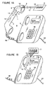
- Figure 4 illustrates the optical scanner 1 incorporated in the handset 4 of the cordless telephone 68.
- the cordless telephone 68 includes a wireless circuit WC1 and an antenna A1 in the handset 4 and a wireless circuit WC2 and an antenna A1 in the telephone base 3.
- the telephone base 3 includes the pulse generator 48, the tone generator 50 and a second controller 70.
- the keypad 58, display 60, memory 56, ringer 62 and additional output devices 64 can be incorporated in the handset 4 or the telephone base 3 or both.
- the trigger 8, scan module 10, digitizer 11, decoder 12 and rechargeable battery 14 are incorporated in the handset 4 for reading the bar codes.
- the optical scanner 1 of the cordless telephone 68 is operated in the same manner as a corded telephone.
- the decoded bar code information is transmitted through the wireless circuit WC1 and antenna A1 of the handset 4 to the antenna A2 and wireless circuit WC2 of the telephone base 3 for processing by the controller 70, the pulse or tone generator 48, 50 and the communication network interface 45 to the telephone line 52.
- the controllers 39 and 70 can bypass the memory either in the handset 4 or the telephone base 3 to transmit the decoded bar code information to the telephone line 52 or can store the decoded bar code information in the memory for transmission onto the telephone line 52 after a predetermined period of time.
- the optical scanner 1 of the handset 4 when used to scan bar codes far from the telephone base and/or when the user wants the controller 39 to enter a store mode, the user can depress a button or the controller enters into a store mode of operation upon detection of weak antenna transmission signals to store the decoded bar code information in the memory.
- the stored information is transmitted to the telephone base 3 for transmission onto the telephone line 52 when the user depresses a transmit button to allow transmission of the stored information and/or when the controller 39 detects a strong antenna signal.
- the stored information can be transmitted to the telephone line 52 when the user places the handset 4 into a cradle (not shown) of the telephone base 3 so that there is a direct linkage between the handset 4 and the telephone base 3 through the contacts 72A, 72B.
- the cordless telephone can be modified to incorporate the optical scanner in a cellular telephone.
- the cellular telephone may employ radio technology, such as spread spectrum for communication signals, to transmit and receive information.
- radio technology such as spread spectrum for communication signals.
- the use of spread spectrum in communications is disclosed in, for example, U.S. Patent Nos. 4,222,115, 4,672,658, 4,888,788, 4,918,707, 4,943,975, 4,964,138, 4,984,247, 5,016,255 and 5,022,047.
- FIG. 5 is a flow chart illustrating the sequence for auto-dialing a called party's telephone number by a caller/user.
- the telephone set is initially set at a standby mode (S1), and the controller waits for an auto-dial button to be depressed (S2). If the caller dials a telephone number instead of the auto-dial button, the controller dials the inputted telephone number (S3) and connection is established (S9, S10). If the auto-dial command is selected by depression of an auto-dial button, the controller waits for the caller/user to either select an appropriate combination of keypad inputs or activate the trigger (S4). When the controller detects keypad inputs, the controller retrieves the pre-stored telephone numbers in the memory for dialing (S5, S9) and establishing connection (S10) between the caller and the called party.
- the caller/user aims the window of the telephone handset at a bar coded telephone number.
- the bar coded telephone number can be printed on the telephone directory, business cards, credit cards, or any available medium having bar coded telephone numbers.
- the caller/user activates the trigger, the bar coded telephone number is scanned and detected by the scan module (S6).
- the digitizer and decoder respectively, digitizes and decodes the electrical signals from the scan module for dialing the decoded telephone number (S6, S9) and establishing connection (S10).
- the display indicates an occurrence of the error.
- the controller instructs the user to re-enter the keypad inputs or re-scan the bar code (S7).
- the controller also tracks the number of error occurrences, and after a predetermined number of error occurrences, the controller terminates the auto-dial feature to instruct the caller/user to enter the telephone number manually (S8). Alternatively, the caller/user can terminate the auto-dial feature any time and dial the number manually.
- Figure 6 illustrates a communication system 74 for transmitting decoded bar code information by a telephone system 75 to a mail-order system 76.
- the telephone system comprises a plurality of telephone sets 6A-6C (only three are shown for illustrative purposes), and each of the telephone set 6A-6C has an optical scanner 1 built into the telephone handset 4 or base 3.
- the communications network 46 couples the telephone system 75 and the mail-order system 76.
- a caller scans bar coded information in a catalog 78 using, for example, the optical scanner 1 incorporated in the handset 4 to order an item 94.
- the catalog 78 has bar coded information 80 identifying the caller such as name, address and telephone number. Further, the catalog 78 includes bar coded item number 82, quantity 84, color 86, size 88 and other information 90 identify the item.
- the catalog 78 also includes bar code shipping method 92 and payment method 93.
- Figure 8 is a flow chart illustrating the sequence for ordering an item using the catalog 78 illustrated in Figure 7 and the telephone set 6A-6C of the telephone system 75 in the communications system 74 illustrated in Figure 6.
- the telephone is initially set at a stand-by mode (S1).
- Portion D (dotted lines) of the method illustrated in Figure 5 is used to either manually dial or auto-dial the telephone number of the mail-order company.
- the caller/user can scan the bar coded telephone number on the catalog to establish connection with the automated mail-ordering system of the mail-order company.
- the automated system instructs the caller/user to enter his/or her bar coded identification 80 identifying the caller's name, address, telephone number and other information printed on the catalog 78 (S11). Such information may be also printed on a driver's license, business card, etc.
- the mail-order system 76 then instructs the caller/user to scan the bar coded item number 82, quantity 84, color 86, size 88 and other information 90 identifying the item on the catalog (S12).
- the mail-order system 76 instructs whether the order is complete (S13). If the caller/user desires to order another item, the caller/user scans the bar coded information of other items (S12), and the sequence is repeated until the caller/user indicates to the automated system that the order is complete. Thereafter, the automated system instructs the caller/user to enter the bar coded shipping method 92, e.g., air or ground, (S14) and asks whether the shipping address is the same as the user identification information (S15). If not, the automated system instructs either to manually enter the shipping address or scan a bar coded shipping address (S16).
- the bar coded shipping method 92 e.g., air or ground
- the automated computer transmits the total amount of the purchase and instructs the caller/user to scan the bar coded payment method 93 on the catalog 78 (S17). If the user scans either payment by check (S18) or C.O.D. (S19), the automated system sends the necessary instructions for such type of purchases (S20, S21) and the purchase is completed (S27). If the user chooses payment by a credit card, the automated system instructs the user to scan the bar coded account number on the credit card (S22). When the decoded account number is received, the automated system confirms the account number (S23). Once confirmed, the user can hang up the telephone to complete the purchase (S27), and the order will process by the mail-order company to deliver the ordered items after payment.
- the automated system instructs the user to re-scan the account number or if desired, manually enter the account number on the telephone keypad (S22). Further, the user can change the method of payment (S17). After a predetermined number of errors (S24), the automated systems asks the user whether he/she desires to talk to a representative or to terminated the order (S25). If the representative is able to help process the order (S25A), the order can be completed (S27), and the connection is terminated. If the user does not want to talk to a representative or the representative is not able to help, the user can hang up to terminate the order (S26).
- the controller conveys the instructions of the automated system to the user using the receiver and/or the display of the telephone set. Further, the scanned and decoded bar code information can be displayed for confirmation.
- a printer can be also attached as an additional output device to print out a hard copy of the order.
- the enter and cancel buttons on the keypad can be used to send and correct scanned information to the automated system. Alternatively, the automated system can instruct the user to confirm the scanned information prior to sending the decoded bar code information.
- the optical scanner in the handset can be used to track of inventory location.
- Clerks can "read" the inventory using the optical scanner of the handset by scanning a bar coded serial number on each piece of inventory to enter the location and status of the piece. (Rather than using a separate computer system, the location and status of the inventory can be processed by a PBX, which has its own computer system.)
- the present invention can be used in business to keep track of inventory and sales.
- a separate bar code reader may be provided to enter the bar coded labels of merchandise during purchase, and a separate computer system used to keep track of inventory and sale.
- the telephone set can be coupled to the cash register, and the bar coded label scanned by the optical scanner of the handset.
- a local PBX computer may be used to keep track of the sales and inventory. At the end of the business day, the local PBX computer can transmit the sales and inventory information to the main computer at the headquarters of the retail store.
Landscapes
- Engineering & Computer Science (AREA)
- Physics & Mathematics (AREA)
- Theoretical Computer Science (AREA)
- General Physics & Mathematics (AREA)
- Artificial Intelligence (AREA)
- Health & Medical Sciences (AREA)
- Computer Vision & Pattern Recognition (AREA)
- Toxicology (AREA)
- General Health & Medical Sciences (AREA)
- Electromagnetism (AREA)
- Signal Processing (AREA)
- General Engineering & Computer Science (AREA)
- Telephonic Communication Services (AREA)
- Selective Calling Equipment (AREA)
- Cash Registers Or Receiving Machines (AREA)
Claims (19)
- Poste de téléphone (6) muni d'un combiné (a) permettant de lire des signes comprenant :ledit combiné (a) du poste de téléphone (6), ledit poste de téléphone (6) étant en outre caractérisé : en ce que ledit combiné comprend un déclencheur (8) destiné à activer ledit lecteur optique pour lire les signes ; et(a) un moyen destiné à émettre et recevoir des signaux audio et sur un réseau de télécommunications ;(b) un lecteur optique (1) comportant :(i) un moyen destiné à émettre un faisceau lumineux le pour balayer les signes ;(ii) un moyen destiné à détecter le faisceau lumineux réfléchi en retour par les signes et à produire des signaux électriques correspondants ; et(iii) un moyen (11, 12) destiné à convertir les signaux électriques en information de signes décodée ; dans lequel ledit lecteur optique (1) se trouve dans
en ce que ledit lecteur optique comprend un moyen destiné à dévier automatiquement ledit faisceau lumineux pour balayer lesdits signes. - Poste de téléphone selon la revendication 1, comprenant en outre un commutateur (54) prévu pour basculer entre deux modes de fonctionnement dudit poste de téléphone.
- Poste de téléphone selon la revendication 2, dans lequel ledit commutateur (54) est prévu pour activer l'un ou l'autre d'un générateur d'impulsions et de tonalité (48, 50) de façon à émettre ladite information de signes décodée comme des impulsions de numérotation ou comme des sons, respectivement, sur ledit réseau de télécommunications.
- Poste de téléphone selon la revendication 1, comprenant en outre un moyen (14) destiné à alimenter en énergie le lecteur optique (1).
- Poste de téléphone selon la revendication 1, comprenant en outre une commande manuelle destinée à entrer et à annuler des signes qui ont été lus par le lecteur optique (1) pour émission sur le réseau de télécommunications.
- Poste de téléphone selon la revendication 1, comprenant en outre : une mémoire (56) destinée à mémoriser l'information de signes décodée, des numéros de téléphone ou des programmes destinés à exécuter des instructions entrées dans le poste de téléphone ; un clavier (58) destiné à recevoir les numéros de téléphone et les instructions ; et un moyen (45) destiné à émettre les signaux audio et l'information de signes décodée et à recevoir des signaux de transmission provenant du réseau de télécommunications.
- Poste de téléphone selon la revendication 1, dans lequel les moyens d'émission et de détection sont incorporés dans un module (10) de balayage comportant : une source (16) de lumière laser (16) destinée à émettre le faisceau lumineux, un système (22) de lentilles destiné à focaliser le faisceau lumineux, un miroir (26) destiné à diriger, vers les signes, le faisceau lumineux focalisé par ledit système de lentilles, un moteur destiné à faire osciller ladite source de lumière laser ou ledit miroir de façon que le faisceau lumineux balaye les signes, et un détecteur (30) destiné à détecter le faisceau lumineux réfléchi par les signes.
- Poste de téléphone selon la revendication 7, dans lequel le moyen d'émission et de réception comprend en outre une fenêtre (20) destinée à faire passer la lumière entre le module de balayage et le moyen de détection.
- Poste de téléphone selon la revendication 1, dans lequel le moyen de conversion comprend : un moyen (11) destiné à numériser les signaux électriques ; et un moyen (12) destiné à décoder les signaux électriques, numérisés par le moyen de numérisation, en information de signes décodée.
- Poste de téléphone selon la revendication 1, dans lequel le poste de téléphone (6) est du type avec cordon, sans cordon ou cellulaire.
- Poste de téléphone selon l'une quelconque des revendications précédentes, raccordé à un réseau de télécommunications, comprenant en outre :un moyen destiné à émettre, sur le réseau de télécommunications, les signaux audio et l'information de signes décodée.
- Poste de téléphone selon la revendication 2, dans lequel le combiné comprend en outre une batterie rechargeable (14) destinée à alimenter en énergie le lecteur optique pendant le fonctionnement en portatif du combiné.
- Poste de téléphone selon la revendication 11, comprenant en outre : une mémoire (56) destinée à mémoriser l'information de signes décodée, des numéros de téléphone ou des programmes destinés à exécuter des instructions entrées dans le poste de téléphone ; un clavier (58) destiné à recevoir les numéros de téléphone ou les instructions ; et un moyen (45) destiné à émettre les signaux audio et l'information de signes décodée au réseau de télécommunications et à recevoir des signaux de transmission provenant du réseau de télécommunications.
- Poste de téléphone selon la revendication 2, dans lequel le combiné comprend une fenêtre (5) destinée à faire passer de la lumière entre le combiné et un code à barres à lire.
- Système de télécommunications destiné à émettre de l'information décodée de code à barres, comprenant : un système de téléphones comprenant une pluralité de postes de téléphone (6A, 6B, 6C) tels que présentés dans l'une quelconque des revendications précédentes, chacun de la pluralité des postes de téléphone comportant un lecteur optique (1) incorporé destiné à lire des codes à barres sur un support imprimé pour émission en tant qu'information décodée de code à barres ; un processeur hôte destiné à recevoir l'information décodée de code à barres et à émettre des instructions vers un le système de téléphones ; et un réseau (46) de télécommunications destiné à établir une connexion entre le système de téléphones et le processeur hôte.
- Système de télécommunications selon la revendication 15, dans lequel le moyen de conversion comprend : un moyen (11) destiné à décoder les signaux électriques numérisés par le moyen de numérisation en information décodée de code à barres.
- Système de télécommunications selon la revendication 15, dans lequel le support imprimé est un catalogue comportant au moins l'un des éléments suivants :des numéros de téléphone sous forme de codes à barres, des identifications d'utilisateurs, des adresses d'utilisateur, de l'information sur des articles, un procédé d'expédition, une adresse d'expédition et un procédé de paiement.
- Système de télécommunications selon la revendication 15, dans lequel le support imprimé est une carte de crédit comportant un numéro de compte sous forme de code à barres.
- Poste de téléphone selon la revendication 1, dans lequel les signes sont des signes de codes à barres.
Priority Applications (1)
| Application Number | Priority Date | Filing Date | Title |
|---|---|---|---|
| EP02001441A EP1204066B1 (fr) | 1993-08-25 | 1994-08-24 | Télécommande et téléphone incorporant des moyens de lecture de code à barre |
Applications Claiming Priority (4)
| Application Number | Priority Date | Filing Date | Title |
|---|---|---|---|
| US11153193A | 1993-08-25 | 1993-08-25 | |
| US27318094A | 1994-07-26 | 1994-07-26 | |
| US273180 | 1994-07-26 | ||
| US111531 | 1998-07-08 |
Related Child Applications (1)
| Application Number | Title | Priority Date | Filing Date |
|---|---|---|---|
| EP02001441A Division EP1204066B1 (fr) | 1993-08-25 | 1994-08-24 | Télécommande et téléphone incorporant des moyens de lecture de code à barre |
Publications (3)
| Publication Number | Publication Date |
|---|---|
| EP0645728A2 EP0645728A2 (fr) | 1995-03-29 |
| EP0645728A3 EP0645728A3 (fr) | 1996-09-04 |
| EP0645728B1 true EP0645728B1 (fr) | 2002-10-30 |
Family
ID=26808997
Family Applications (2)
| Application Number | Title | Priority Date | Filing Date |
|---|---|---|---|
| EP02001441A Expired - Lifetime EP1204066B1 (fr) | 1993-08-25 | 1994-08-24 | Télécommande et téléphone incorporant des moyens de lecture de code à barre |
| EP94113239A Expired - Lifetime EP0645728B1 (fr) | 1993-08-25 | 1994-08-24 | Télécommande et téléphone incorporant des moyens de lecture de code à barre |
Family Applications Before (1)
| Application Number | Title | Priority Date | Filing Date |
|---|---|---|---|
| EP02001441A Expired - Lifetime EP1204066B1 (fr) | 1993-08-25 | 1994-08-24 | Télécommande et téléphone incorporant des moyens de lecture de code à barre |
Country Status (4)
| Country | Link |
|---|---|
| EP (2) | EP1204066B1 (fr) |
| JP (1) | JPH07154456A (fr) |
| CA (1) | CA2130319A1 (fr) |
| DE (2) | DE69431616T2 (fr) |
Cited By (2)
| Publication number | Priority date | Publication date | Assignee | Title |
|---|---|---|---|---|
| US6907568B1 (en) | 2001-04-09 | 2005-06-14 | Nokia Corporation | Tangible icon representing network objects |
| US8065201B2 (en) | 1996-10-25 | 2011-11-22 | Ipf, Inc. | Internet-based method of and system for managing and delivering consumer product information at points along the world wide web using consumer product information (CPI) requesting and graphical user interface (GUI) displaying subsystems driven by server-side components and managed by consumer product manufactures and/or authorized parties |
Families Citing this family (48)
| Publication number | Priority date | Publication date | Assignee | Title |
|---|---|---|---|---|
| US5992752A (en) | 1993-11-24 | 1999-11-30 | Metrologic Instruments, Inc. | Internet-based system for enabling information-related transactions over the internet using Java-enabled internet terminals provided with bar code symbol readers for reading Java-Applet encoded bar code symbols |
| US6375078B1 (en) | 1990-09-11 | 2002-04-23 | Metrologic Instruments, Inc. | Universal transaction machine for carrying out information-related transactions using html-encoded documents embodying transaction-enabling java-applets automatically launched and executed in response to reading code symbols |
| US6988662B2 (en) | 1997-06-04 | 2006-01-24 | Metrologic Instruments, Inc. | System and method for carrying out information-related transactions using web documents embodying transaction-enabling applets automatically launched and executed in response to reading url-encoded symbols pointing thereto |
| US6068188A (en) | 1993-11-24 | 2000-05-30 | Metrologic Instruments, Inc. | System and method for composing menus of URL-encoded bar code symbols while using internet browser program |
| US6076733A (en) | 1993-11-24 | 2000-06-20 | Metrologic Instruments, Inc. | Web-based system and method for enabling a viewer to access and display HTML-encoded documents located on the world wide web (WWW) by reading URL-encoded bar code symbols printed on a web-based information resource guide |
| US5905251A (en) | 1993-11-24 | 1999-05-18 | Metrologic Instruments, Inc. | Hand-held portable WWW access terminal with visual display panel and GUI-based WWW browser program integrated with bar code symbol reader in a hand-supportable housing |
| US6942150B2 (en) | 1993-11-24 | 2005-09-13 | Metrologic Instruments, Inc. | Web-based mobile information access terminal |
| US5918214A (en) | 1996-10-25 | 1999-06-29 | Ipf, Inc. | System and method for finding product and service related information on the internet |
| EP0744856A3 (fr) * | 1995-05-26 | 1997-06-25 | At & T Corp | Appareil et méthode pour l'utilisation de codes d'identification de produit pour établir des connexions de communication |
| US6505776B1 (en) | 1995-06-07 | 2003-01-14 | Metrologic Instruments, Inc. | System for storing, accessing and displaying html-encoded documents relating to an object being worked upon in a work environment by a human operator wearing a wireless http-enabled client system equipped with a code symbol reader programmed to read a url-encoded symbol on the object, access said html-encoded documents from http-enabled information servers connected to an information network, and display same for review while working said object |
| DE29518675U1 (de) * | 1995-11-24 | 1996-02-08 | HELICOM Entwicklungsgesellschaft für Telekommunikation und Medientechnik mbH, 48157 Münster | Vorrichtung zur Datenübertragung von einem Barcode-Stift zu einem Handy |
| CN1244933A (zh) | 1996-10-25 | 2000-02-16 | Ipf股份有限公司 | 互联网上消费品信息管理服务系统及其方法 |
| CA2272467C (fr) | 1996-11-25 | 2005-03-29 | David M. Wilz, Sr. | Systemes pilotes par symboles sous forme de codes a barres pour acceder a des ressources d'information sur l'internet |
| US6386453B1 (en) | 1996-11-25 | 2002-05-14 | Metrologic Instruments, Inc. | System and method for carrying out information-related transactions |
| DE19702077A1 (de) * | 1997-01-22 | 1998-07-23 | Eastman Kodak Co | Verfahren und Anordnung zur Verfolgung und Kontrolle der Auslieferung und/oder Abholung von Waren/Warenbehältern |
| US6321992B1 (en) | 1997-03-19 | 2001-11-27 | Metrologic Instruments, Inc. | Internet-based system and method for tracking objects bearing URL-encoded bar code symbols |
| WO1999017230A1 (fr) * | 1997-09-26 | 1999-04-08 | Johan Schlasberg | Systeme de messages informations |
| US6959286B2 (en) | 1997-10-27 | 2005-10-25 | Ipf, Inc. | Method and system for searching a dynamically updated database of UPN/TM/PD and URL data links |
| US7089199B2 (en) | 1997-10-27 | 2006-08-08 | Metrologic Instruments, Inc. | System for and method of managing and delivering manufacturer-specified consumer product information to consumers in the marketplace |
| GB2345609A (en) * | 1999-01-11 | 2000-07-12 | William Henry Player | Data handling system |
| JP3780811B2 (ja) * | 1999-03-30 | 2006-05-31 | 富士通株式会社 | ワイヤレステレビ電話を用いた電子ショッピングシステム |
| JP4569939B2 (ja) * | 1999-05-24 | 2010-10-27 | ローム株式会社 | 携帯形電話機 |
| AUPQ439299A0 (en) * | 1999-12-01 | 1999-12-23 | Silverbrook Research Pty Ltd | Interface system |
| FI991494A7 (fi) * | 1999-06-30 | 2000-12-31 | Nokia Corp | Objektin identifiointi |
| JP2001160105A (ja) | 1999-09-22 | 2001-06-12 | Sony Corp | 情報処理システム、携帯電話機及び情報処理方法 |
| DE10005528A1 (de) * | 1999-12-07 | 2001-07-12 | Martin Schmid | Verfahren zum Aufrufen einer URL-Adresse im Internet |
| SE518290C2 (sv) | 1999-12-29 | 2002-09-17 | Ericsson Telefon Ab L M | Bärbar kommunikationsapparat med en optisk eller magnetisk läsanordning |
| NO311658B1 (no) * | 2000-03-27 | 2001-12-27 | Scan & Pay As | Fremgangsmåte for å gjennomföre handel og betalings- /kredittformidling |
| EP1146449B1 (fr) * | 2000-04-11 | 2002-01-09 | Peter Lammerhuber | Installation et téléphone mobile pour la génération de profils d'utilisation |
| SE522970C2 (sv) * | 2000-05-05 | 2004-03-23 | Ericsson Telefon Ab L M | Förfarande, system, streckkodläsare och datorprogramprodukt för att länka en streckkod till en webbsida |
| US6854641B1 (en) | 2000-11-02 | 2005-02-15 | Kabushiki Kaisha Toshiba | Electronic information management system |
| GB0204686D0 (en) | 2002-02-28 | 2002-04-17 | Koninkl Philips Electronics Nv | Interactive system using tags |
| US20080255931A1 (en) * | 2004-03-30 | 2008-10-16 | Dainichiseika Color & Chemicals Mfg. Co. Ltd. | Print Ink System and Print Method Used For Print 'It' Shopping-Linked Printed Matter and Print 'It' Shopping-Linked Printed Matter |
| JP2006227765A (ja) * | 2005-02-16 | 2006-08-31 | Tambourine Producers Inc | 情報端末装置及びアラーム発生方法 |
| JP2009077120A (ja) * | 2007-09-20 | 2009-04-09 | Nakayo Telecommun Inc | 電話番号情報読取転送機能を有する電話装置 |
| US8251290B1 (en) | 2008-03-06 | 2012-08-28 | Sprint Communications Company L.P. | Bar code validation using a wireless communication device |
| US9154899B1 (en) | 2008-03-06 | 2015-10-06 | Sprint Communications Company L.P. | Communication transceiver configuration in response to optically receiving an image in a wireless communication device |
| WO2009114710A2 (fr) | 2008-03-14 | 2009-09-17 | Neomedia Technologies, Inc. | Système d’échange de messages |
| US8254785B1 (en) | 2008-05-15 | 2012-08-28 | Sprint Communications Company L.P. | Optical image processing to wirelessly transfer a voice message |
| US8000727B1 (en) | 2008-10-15 | 2011-08-16 | Sprint Communications Company L.P. | Optical image processing for accessing building control from a wireless communication device |
| US8195227B1 (en) | 2008-11-21 | 2012-06-05 | Sprint Communications Company L.P. | Optical image processing for image set decoding from a wireless communication device |
| CN101840492B (zh) * | 2010-05-25 | 2013-11-06 | 福建新大陆电脑股份有限公司 | 一种支持多码制并行处理的条码解码装置 |
| US8463239B1 (en) | 2011-02-11 | 2013-06-11 | Sprint Communications Company L.P. | Secure reconfiguration of wireless communication devices |
| CN108574784A (zh) * | 2017-03-09 | 2018-09-25 | 上海传英信息技术有限公司 | 一种手机充值方法及系统 |
| US11790722B2 (en) | 2020-08-11 | 2023-10-17 | Best Lockers, Llc | Single-sided storage locker systems accessed and controlled using machine-readable codes scanned by mobile phones and computing devices |
| US11995943B2 (en) | 2020-08-11 | 2024-05-28 | ScooterBug, Inc. | Methods of and systems for controlling access to networked devices provided with machine-readable codes scanned by mobile phones and computing devices |
| US11631295B2 (en) | 2020-08-11 | 2023-04-18 | ScooterBug, Inc. | Wireless network, mobile systems and methods for controlling access to lockers, strollers, wheel chairs and electronic convenience vehicles provided with machine-readable codes scanned by mobile phones and computing devices |
| US12479521B2 (en) | 2020-08-11 | 2025-11-25 | ScooterBug, Inc. | Wireless network, systems and methods for configuration, operation and use of motorized, wheeled and steerable passenger-carrying carts for entertainment purposes |
Family Cites Families (8)
| Publication number | Priority date | Publication date | Assignee | Title |
|---|---|---|---|---|
| DE3687127T2 (de) * | 1985-02-28 | 1993-05-06 | Symbol Technologies Inc | Tragbarer abtastkopf mit einer laserdiode. |
| JPS63275250A (ja) * | 1987-05-06 | 1988-11-11 | Hashimoto Corp | バ−コ−ドリ−ダ付ハンドセット |
| DE3878653D1 (de) * | 1987-09-14 | 1993-04-01 | Autophon Ascom Ag | Telefonstation mit einem teilnehmerverzeichnis. |
| DE3741788C2 (de) * | 1987-12-10 | 1995-02-16 | Telefonbau & Normalzeit Gmbh | Fernsprechapparat mit einer Sendeeinrichtung |
| DE3814728A1 (de) * | 1988-04-30 | 1989-11-09 | Telefonbau & Normalzeit Gmbh | Drahtloses fernsprechsystem |
| DE4109482C2 (de) * | 1991-03-22 | 1994-10-20 | Hagenuk Telecom Gmbh | Vorrichtung für Telekommunikationsanlagen |
| EP0535220A4 (en) * | 1991-04-16 | 1993-09-22 | John Barrus | Method and apparatus for the ordering from remote locations |
| JPH0550738A (ja) * | 1991-08-23 | 1993-03-02 | Dainippon Printing Co Ltd | 透明不可視マーク付カタログとそれを用いた予約発注システム |
-
1994
- 1994-08-17 CA CA002130319A patent/CA2130319A1/fr not_active Abandoned
- 1994-08-24 EP EP02001441A patent/EP1204066B1/fr not_active Expired - Lifetime
- 1994-08-24 DE DE69431616T patent/DE69431616T2/de not_active Expired - Lifetime
- 1994-08-24 DE DE69434273T patent/DE69434273T2/de not_active Expired - Fee Related
- 1994-08-24 EP EP94113239A patent/EP0645728B1/fr not_active Expired - Lifetime
- 1994-08-25 JP JP6200449A patent/JPH07154456A/ja active Pending
Cited By (3)
| Publication number | Priority date | Publication date | Assignee | Title |
|---|---|---|---|---|
| US8065201B2 (en) | 1996-10-25 | 2011-11-22 | Ipf, Inc. | Internet-based method of and system for managing and delivering consumer product information at points along the world wide web using consumer product information (CPI) requesting and graphical user interface (GUI) displaying subsystems driven by server-side components and managed by consumer product manufactures and/or authorized parties |
| US8458055B2 (en) | 1996-10-25 | 2013-06-04 | Ipf, Inc. | Internet-based method of and system for managing and delivering consumer product information at points along the world wide web using consumer product information (CPI) requesting and graphical user interface (GUI) displaying subsystems driven by server-side objects and managed by consumer product manufacturers and/or authorized parties |
| US6907568B1 (en) | 2001-04-09 | 2005-06-14 | Nokia Corporation | Tangible icon representing network objects |
Also Published As
| Publication number | Publication date |
|---|---|
| EP1204066B1 (fr) | 2005-02-09 |
| DE69434273T2 (de) | 2006-01-12 |
| EP0645728A3 (fr) | 1996-09-04 |
| EP1204066A2 (fr) | 2002-05-08 |
| DE69431616D1 (de) | 2002-12-05 |
| DE69431616T2 (de) | 2003-07-03 |
| DE69434273D1 (de) | 2005-03-17 |
| JPH07154456A (ja) | 1995-06-16 |
| EP0645728A2 (fr) | 1995-03-29 |
| EP1204066A3 (fr) | 2002-05-29 |
| CA2130319A1 (fr) | 1995-02-26 |
Similar Documents
| Publication | Publication Date | Title |
|---|---|---|
| EP0645728B1 (fr) | Télécommande et téléphone incorporant des moyens de lecture de code à barre | |
| US5107100A (en) | Portable scanner with on-board keyboard, display, transceiver and printer | |
| US5324924A (en) | Bar code decoder with changeable working ranges | |
| US5532469A (en) | Hand held bar code reader with input and display device and processor | |
| US5340972A (en) | Hands-free bar code scanner with finger activated optical control | |
| US5801371A (en) | Optical reader with independent triggering and graphical user interface | |
| US6158662A (en) | Triggered optical reader | |
| US6607134B1 (en) | Finger-mounted readers with low power radio frequency communications | |
| US6814293B2 (en) | Arrangement for and method of establishing a logical relationship among peripherals in a wireless local area network | |
| US6764012B2 (en) | Signaling arrangement for and method of signaling in a wireless local area network | |
| US5280162A (en) | Object sensing system for bar code laser scanners | |
| US6415982B2 (en) | Triggered data collector and data transmitter | |
| US5675139A (en) | Interface arrangement for use with consumer devices | |
| CN107273773B (zh) | 具有手势接口的成像器读取器 | |
| US6145743A (en) | Light collection systems in electro-optical readers | |
| US6882863B2 (en) | Portable communication apparatus having an optical or magnetic reading device | |
| EP2397967B1 (fr) | Terminal de données portables avec lampe torche intégrée | |
| JPH09307617A (ja) | 電話機 | |
| US5744791A (en) | Solar energy-powered optical reader | |
| US20070007353A1 (en) | Laser scanner module having integral interface with hand-held data capture terminal, proximity and label sensing, and enhanced sensitivity and power efficiency | |
| EP2472434A1 (fr) | Terminal de lecture de vignettes doté de caractéristiques de fonctionnement configurables | |
| US20050248471A1 (en) | Method and apparatus for displaying a time-varying code to a handheld terminal, and method and apparatus for approval authentication processing by using the same | |
| US5745794A (en) | System for converting signals into a predetermined data exchange format with plug-in modular connector having voltage, ground, data, and clock terminals for a scanning head | |
| JPH0612511A (ja) | ハンズフリー型バーコード走査装置及びその操作方法 | |
| US5294784A (en) | Apparatus for scanning and downloading data |
Legal Events
| Date | Code | Title | Description |
|---|---|---|---|
| PUAI | Public reference made under article 153(3) epc to a published international application that has entered the european phase |
Free format text: ORIGINAL CODE: 0009012 |
|
| AK | Designated contracting states |
Kind code of ref document: A2 Designated state(s): DE FR GB IT |
|
| PUAL | Search report despatched |
Free format text: ORIGINAL CODE: 0009013 |
|
| AK | Designated contracting states |
Kind code of ref document: A3 Designated state(s): DE FR GB IT |
|
| 17P | Request for examination filed |
Effective date: 19970303 |
|
| 17Q | First examination report despatched |
Effective date: 19990427 |
|
| GRAG | Despatch of communication of intention to grant |
Free format text: ORIGINAL CODE: EPIDOS AGRA |
|
| GRAG | Despatch of communication of intention to grant |
Free format text: ORIGINAL CODE: EPIDOS AGRA |
|
| GRAH | Despatch of communication of intention to grant a patent |
Free format text: ORIGINAL CODE: EPIDOS IGRA |
|
| GRAH | Despatch of communication of intention to grant a patent |
Free format text: ORIGINAL CODE: EPIDOS IGRA |
|
| GRAH | Despatch of communication of intention to grant a patent |
Free format text: ORIGINAL CODE: EPIDOS IGRA |
|
| GRAH | Despatch of communication of intention to grant a patent |
Free format text: ORIGINAL CODE: EPIDOS IGRA |
|
| GRAA | (expected) grant |
Free format text: ORIGINAL CODE: 0009210 |
|
| AK | Designated contracting states |
Kind code of ref document: B1 Designated state(s): DE FR GB IT |
|
| REG | Reference to a national code |
Ref country code: GB Ref legal event code: FG4D |
|
| REF | Corresponds to: |
Ref document number: 69431616 Country of ref document: DE Date of ref document: 20021205 |
|
| RAP2 | Party data changed (patent owner data changed or rights of a patent transferred) |
Owner name: SYMBOL TECHNOLOGIES, INC. |
|
| ET | Fr: translation filed | ||
| PLBE | No opposition filed within time limit |
Free format text: ORIGINAL CODE: 0009261 |
|
| STAA | Information on the status of an ep patent application or granted ep patent |
Free format text: STATUS: NO OPPOSITION FILED WITHIN TIME LIMIT |
|
| 26N | No opposition filed |
Effective date: 20030731 |
|
| REG | Reference to a national code |
Ref country code: DE Ref legal event code: R082 Ref document number: 69431616 Country of ref document: DE Representative=s name: SCHUMACHER & WILLSAU PATENTANWALTSGESELLSCHAFT, DE |
|
| PGFP | Annual fee paid to national office [announced via postgrant information from national office to epo] |
Ref country code: DE Payment date: 20130902 Year of fee payment: 20 |
|
| PGFP | Annual fee paid to national office [announced via postgrant information from national office to epo] |
Ref country code: GB Payment date: 20130726 Year of fee payment: 20 Ref country code: FR Payment date: 20130725 Year of fee payment: 20 |
|
| PGFP | Annual fee paid to national office [announced via postgrant information from national office to epo] |
Ref country code: IT Payment date: 20130819 Year of fee payment: 20 |
|
| REG | Reference to a national code |
Ref country code: DE Ref legal event code: R071 Ref document number: 69431616 Country of ref document: DE |
|
| REG | Reference to a national code |
Ref country code: GB Ref legal event code: PE20 Expiry date: 20140823 |
|
| PG25 | Lapsed in a contracting state [announced via postgrant information from national office to epo] |
Ref country code: DE Free format text: LAPSE BECAUSE OF EXPIRATION OF PROTECTION Effective date: 20140826 |
|
| PG25 | Lapsed in a contracting state [announced via postgrant information from national office to epo] |
Ref country code: GB Free format text: LAPSE BECAUSE OF EXPIRATION OF PROTECTION Effective date: 20140823 |