EP0647104B1 - Schuhwerk - Google Patents
Schuhwerk Download PDFInfo
- Publication number
- EP0647104B1 EP0647104B1 EP92922508A EP92922508A EP0647104B1 EP 0647104 B1 EP0647104 B1 EP 0647104B1 EP 92922508 A EP92922508 A EP 92922508A EP 92922508 A EP92922508 A EP 92922508A EP 0647104 B1 EP0647104 B1 EP 0647104B1
- Authority
- EP
- European Patent Office
- Prior art keywords
- pumping chamber
- footwear
- air
- ventilated footwear
- air inlet
- Prior art date
- Legal status (The legal status is an assumption and is not a legal conclusion. Google has not performed a legal analysis and makes no representation as to the accuracy of the status listed.)
- Expired - Lifetime
Links
- 238000005086 pumping Methods 0.000 claims abstract description 81
- 230000002093 peripheral effect Effects 0.000 claims abstract description 7
- 230000006835 compression Effects 0.000 claims description 19
- 238000007906 compression Methods 0.000 claims description 19
- 239000000463 material Substances 0.000 claims description 6
- 125000004122 cyclic group Chemical group 0.000 claims description 4
- 238000013459 approach Methods 0.000 claims description 2
- 238000010438 heat treatment Methods 0.000 claims 1
- 238000009423 ventilation Methods 0.000 description 6
- 230000000694 effects Effects 0.000 description 5
- 239000012530 fluid Substances 0.000 description 5
- 238000011068 loading method Methods 0.000 description 4
- 230000035939 shock Effects 0.000 description 4
- XLYOFNOQVPJJNP-UHFFFAOYSA-N water Substances O XLYOFNOQVPJJNP-UHFFFAOYSA-N 0.000 description 4
- 230000000903 blocking effect Effects 0.000 description 3
- 230000000295 complement effect Effects 0.000 description 3
- 238000001816 cooling Methods 0.000 description 3
- 230000033228 biological regulation Effects 0.000 description 2
- 238000010276 construction Methods 0.000 description 2
- 229920002994 synthetic fiber Polymers 0.000 description 2
- 238000010521 absorption reaction Methods 0.000 description 1
- 230000002411 adverse Effects 0.000 description 1
- 238000004891 communication Methods 0.000 description 1
- 230000002538 fungal effect Effects 0.000 description 1
- 230000006698 induction Effects 0.000 description 1
- 230000001939 inductive effect Effects 0.000 description 1
- 238000009413 insulation Methods 0.000 description 1
- 230000003993 interaction Effects 0.000 description 1
- 238000004519 manufacturing process Methods 0.000 description 1
- 238000000034 method Methods 0.000 description 1
- 238000012986 modification Methods 0.000 description 1
- 230000004048 modification Effects 0.000 description 1
- 229920003023 plastic Polymers 0.000 description 1
- 239000004033 plastic Substances 0.000 description 1
- 238000011084 recovery Methods 0.000 description 1
- 230000001105 regulatory effect Effects 0.000 description 1
- 238000010792 warming Methods 0.000 description 1
Images


Classifications
-
- A—HUMAN NECESSITIES
- A43—FOOTWEAR
- A43B—CHARACTERISTIC FEATURES OF FOOTWEAR; PARTS OF FOOTWEAR
- A43B17/00—Insoles for insertion, e.g. footbeds or inlays, for attachment to the shoe after the upper has been joined
- A43B17/08—Insoles for insertion, e.g. footbeds or inlays, for attachment to the shoe after the upper has been joined ventilated
-
- A—HUMAN NECESSITIES
- A43—FOOTWEAR
- A43B—CHARACTERISTIC FEATURES OF FOOTWEAR; PARTS OF FOOTWEAR
- A43B7/00—Footwear with health or hygienic arrangements
- A43B7/06—Footwear with health or hygienic arrangements ventilated
- A43B7/08—Footwear with health or hygienic arrangements ventilated with air-holes, with or without closures
- A43B7/082—Footwear with health or hygienic arrangements ventilated with air-holes, with or without closures the air being expelled to the outside
Definitions
- This invention relates to improvements to footwear.
- This invention has particular application to sporting footwear such as sneakers and joggers and hereinafter generally referred to as sneakers but of course it is not limited thereto and can be used in boots, shoes and slippers and the like. However for illustrative purposes only, particular reference will be made hereinafter to its application to sneakers.
- Footwear is also used for activities on cold surfaces and by persons with poor circulation to their extremities including their feet. At present the most common remedy for such conditions is to wear thick socks as insulation against ingress of the cold. This is only partially effective and may cause discomfort to the user.
- the present invention aims to alleviate at least one of the abovementioned disadvantages and to provide improvements to footwear which will be effective in use.
- this invention in one aspect resides broadly in ventilation means for ventilating a footwear, including pump means arranged in reactive relationship with the footwear such that in use loading placed upon the footwear will cause the pump means to ventilate the footwear.
- the ventilation may be effected by pumping air to, from or within the footwear.
- the pump assembly may be of basic form and be constituted by a pumping chamber biassed to an expanded position to induce air therein which is expelled upon compression of the pumping chamber.
- the pump assembly may be in the form of a pumping chamber incorporating valving for selectively pumping air within the footwear.
- the ventilation means may be adapted to induce a cooling effect or a warming effect to the footwear.
- the pump assembly may include a pumping chamber having separate air inlet and air outlet means provided with non-return valves or the pumping chamber may be provided with openings within the footwear through which air is admitted and expelled to and from the pumping chamber as a result of foot action relative to those openings within the footwear.
- the pumping chamber is biased to an expanded position such that after compression it will automatically expand to induce air into the pumping chamber.
- the biassing means may be an internal coil spring or the like or it constituted by the material and form of the pumping chamber.
- the pumping chamber could be adapted to be positively expanded by a linkage or line means operated by longitudinal deformation of the footwear sole during successive cycles of use.
- a tension member may extend between the toe of the sole and the heel such that flexing of the toe portion relative to the remainder of the sole draws the pumping chamber to an expanded attitude for subsequent compression by the weight of the user bearing upon the sole.
- a pump actuating member may depend from the footwear and be forced upwardly in a pumping action relative to the footwear upon movement of the footwear towards the ground.
- the pumping chamber is in the form of an insole assembly having air supply ducts extending along opposing sides thereof and communicating with an air pumping chamber disposed between the air supply ducts and non-return valves interconnecting the air supply ducts with the pumping chamber. Air may be expelled from or drawn into the pumping chamber and expelled upwardly through the outlets into the footwear. If desired only one air supply duct may be provided to act as an inlet or outlet and a complementary outlet/inlet may be arranged around the side of the insert to communicate with apertures in the sidewall of the shoe.
- the or each air inlet has an elevated inlet opening so as to alleviate the pumping of moisture or water through the pumping chamber when the footwear is worn in wet conditions.
- the air outlets from the footwear could be placed in the lower portion or sole if desired.
- the or each air inlet is also provided with filter means adapted to exclude the passage of dirt and other foreign matter and reduce entry of water to the air supply means.
- the ventilating means may be provided as an insert or it may be formed integrally with the footwear. Furthermore the outlets associated with the pumping chamber may be so formed as to permit restricted discharge of air therefrom such that the pumping chamber provides a selected degree of cushioning or shock absorption beneath the user's feet. If desired the air outlet may be progressively adjustable from fully open to fully closed and suitably by control means incorporated into the heel of the footwear.
- this invention resides broadly in footwear including ventilation means for ventilating the footwear, the ventilation means including a pump assembly arranged in reactive relationship with the footwear such that in use loading placed upon the footwear will actuate the pump causing air to be circulated through the footwear.
- this invention resides broadly in footwear having shock absorbing means including a fluid compression chamber arranged whereby operative supporting loads applied to the footwear will compress the compression chamber and compression chamber outlet regulation means for regulating the rate of discharge of fluid from said compression chamber.
- the fluid may be air which is discharged to atmosphere or it may be a fluid which is discharged to a holding chamber from which fluid may be returned to the compression chamber.
- the compression chamber is a heel compression chamber.
- the regulation means may be fixed or externally adjustable valve means and may be a in the form of a non-return valve assembly.
- this invention resides broadly in a sole assembly including:-
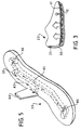
- the ventilating means 10 illustrated in Fig. 1 is in the form of an insole assembly 9 comprising an upper flow-through pad 11 and a lower pumping assembly 12.
- the pumping assembly 12 includes a compartmentalised pumping chamber 14 and peripheral air supply chamber 13 extending thereabout.
- the pumping chamber 14 is provided with a series of air outlets 15 on its upper surface, each of which is associated with a non-return valve such as the flap valves 16.
- Further non-return valves 17 are supported along the inner wall of the pumping chamber and form controlled inlets 18 through which the pumping chamber communicates with the air supply chamber 13.
- the pumping assembly 12 is formed of a resilient plastics material which exhibits elastic recovery after each cycle of compression by foot pressure.
- the air supply chamber 13 is provided with a pair of air inlets 19 which communicate through snorkel like ducts 20 with filtered air inlets 21 adjacent the upper rear edge of the foot opening 22.
- a cycle of repeated operations may be commenced resultant from the user's weight upon the sole of the footwear cyclically compressing the pumping chamber 14 and causing air to drawn therein through the inlets 18 and be expelled through the non-return valves 16 for distribution to the interior of the footwear through the flow-through foot pad 11.
- the pumping chamber 14 expands elastically when the user's weight is removed from the footwear, thus causing air to be induced through the non-return valves 17 from the air supply chambers 13.
- the non-return valves 17 close the inlets 18 such that on commencement of the next cycle of operations air is once again expelled into the interior of the footwear through the outlets 15.
- the chamber 13 communicates with the filtered air inlets 21 for air supply from a position elevated above the ground. This is to enable the footwear to be used in damp conditions or in shallow puddles without ingesting water into the pumping chamber.
- FIG. 4 illustrates the presently preferred embodiment of the invention adapted for inducing a cooling air flow through the footwear 30.
- footwear is constructed with an integral pumping chamber 31 moulded into the heel section of the sole assembly 32 and adapted to co-operate with a ducted insole 33 through respective inlet and outlet non-return valves 34 and 35.
- the ducted insole 33 is diagrammatically illustrated in FIG. 5.
- the outlet 44 may include a filter.
- the inside arch portion of the footwear is chosen as there is little pressure on the side of the footwear at this region and thus placement of the exhaust tube 43 at this position should not reduce comfort for a user. Furthermore it will be seen that the passage length between the non-return valves 34 and 35 and the outlet 44 is relatively long. This is provided to damp out and thus reduce the effect the noise emitted from operation of the non-return valves 34 and 35.
- non-return valves 34 and 35 are fixed to the ducted insole 33 such that when it is removed from the footwear the valves 34 and 35 release from their press-seal fit into the inlet aperture 37 and the outlet aperture 38 in the sole assembly 32 for communication with the pumping chamber 31. This allows for easy servicing or replacement of the non-return valves 34/35 as required. Furthermore the insert together with the valves 34/35 may be removed to enable the footwear to be washed and any water drained from the pumping chamber 31 by inverting the footwear.
- the pumping chamber 31 is located in the heel portion 50 because of the available thickness of the sole assembly 32 in this area and because of the high pressure that is applied to this part of the sole assembly 32 in use, upon contact with the ground.
- the compression chamber includes a central portion 45 having substantially parallel upper and lower walls 46 and 47 and converging upper and lower peripheral walls as illustrated, so as to maintain operative lateral stability of the sole while allowing for substantially parallel movement between the top and bottom walls 46 and 47 between the expanded and compressed attitudes.
- the converging upper and lower peripheral walls are formed such that the front of the air chamber 31 is of a deep wedge shape whereas the back and side converging walls of the air chamber 31 are of a shallow wedge form and are so formed that the outermost edge 48 maintains a constant distance from the outer face 49 of the sole to provide a substantially even thickness of material supporting the sole assembly 32 above the pumping chamber 31.
- the arrangement is such that when compressed the volume of the pumping chamber 31 approaches zero and the line of the ducted insole straightens along the length of the footwear to substantially conform to the line of a standard sneaker.
- the uppers 51 may be formed so as to be able to expand and contract slightly ion front of the foot opening. It is considered that this will assist in the vertical pumping action of the upper heel 52 relative to the lower heel 53.
- the non-return valves 34/35 may be of a type in which the effective opening provided thereby may be adjustable or alternatively they may be of the type which may be readily replaced to modify the valve operating characteristics, such as to suit a user's needs.
- a slide valve could be provided in the ducted insole at the base of the exhaust non-return valve. The slide valve could be utilised to vary the aperture through which air could be exhausted from the non-return valve into the ducted insole.
- the inside surface of the uppers 51 may include ribs to form air flow paths to assist flow of air to the inlet 40 and past the areas of the foot to be ventilated.
- the heel section 60 of the footwear 61 is hingedly attached to the sole assembly 62 by a transverse hinge 63.
- the heel section contains a recess 64 in its upper surface in which a compressible air bag is supported and cooperating with a complementary protrusion 65 formed in the underside of the sole assembly 62 above the recess 64.
- Suitable valving means are provided to duct air pumped by the compressible air bag upon cyclic intake and compression resulting from movement of complementary protrusion 65 into the recess 64 at each step and compression of the air bag therein.
- the air bag may be biassed to an expanded configuration, such as by the movement of the heel section 60 pivotally away from the sole section 62 when user's weight is removed from the footwear.
- the footwear 70 may include a pumping chamber 71 mounted externally at the rear thereof and including a vertically reciprocable plunger adapted to be forced upwardly into the chamber 71 to cause the required air pumping action.
- the plunger 72 extends downwardly from the underside of the footwear 70 such that it will be pushed upwardly in a pumping action upon cyclic contact between the footwear and the ground.
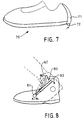
- FIG. 8 An alternative arrangement is illustrated in FIG. 8 wherein distortion of the footwear in use is utilised to actuate the pumping means.
- an externally mounted cylinder pump assembly 80 is supported between a fixed lower mounting 81 and a fixed upper mounting 82.
- mounting 82 moves upwardly and forwardly relative to the mounting 81 with the result that the distance between the mountings 81 and 82 is cyclically compressed and extended resulting in a pumping action by the cylindrical pump assembly 80.
- the characteristics of the footwear which incorporates non-return inlet and outlet valves to a pumping chamber may be operatively varied by either maintaining either or both valves open or closed. Furthermore, the characteristics may be varied by providing a separate and adjustable relief valve for the pumping chamber, by providing additional passages each able to interchangeably communicate with the pumping chamber and selectable to vary the operating characteristics, or by blocking either or both the inlet and outlet passages to the pumping chamber.
- the exhaust tube 90 of the ducted insole 91 is provided with a slide actuator 93 linked to a flap valve 94 by a flexible push/pull cable 95 whereby the flap valve 94 may be moved between a normal position at which it closes an opening 96 interconnecting the inlet passage 97 to the outlet passage 98 and a blocking position at which it blocks flow through the inlet passage 97.
- the flap valve When the flap valve is in the normal position the operation is as described with reference to FIG. 6.
- the flap valve is in the blocking position, the inlet passage 97 communicates with the outlet passage 98 and air is circulated through the exhaust tube 90.
- the pump assembly may be adapted to induce cooling air into the footwear by arranging the inlet adjacent the toe area and by exhausting to atmosphere or it may be adapted to heat the footwear by exhausting internally of the footwear and taking its inlet from the exterior of the footwear.
Landscapes
- Health & Medical Sciences (AREA)
- Epidemiology (AREA)
- General Health & Medical Sciences (AREA)
- Public Health (AREA)
- Footwear And Its Accessory, Manufacturing Method And Apparatuses (AREA)
Claims (15)
- Belüftetes Schuhwerk [30]des Typs mit einer federnden Sohlenbaugruppe [32], einer Pumpkammer [31], Vorspannmittel [48], das genannte Pumpkammer [31] auf eine expandierte Einstellung vorspannt und genannte Pumpkammer im wesentlichen innerhalb des Absatzes der Sohlenbaugruppe [32]für zyklische Verdichtung durch die Ferse eines Benutzers enthalten ist und im zusammengepreßten Zustand einen Volumen von annähernd Null aufweist, UND DADURCH GEKENNZEICHNET, DASS:genannte Pumpkammer [31]sich in Richtung der lateralen Extremitäten des Absatzes verjüngt;eine Lufteinlaßdurchgang [41] zu genannter Pumpkammer [31] erstreckt sich ab Lufteinlässen [40]in der Sohlenbaugruppe [32]anschließend an den Zehenbereich und zur Pumpkammer [31], wodurch Luft nur ab den genannten Lufteinlässen [40]im Zehenbereich zur Pumpkammer [31]eingeleitet werden kann;ein Luftauslaßdurchgang [42] aus genannter Pumpkammer [31]entlüftet zum Äußeren des Schuhwerks, und entsprechende, entgegengesetzt angeordnete Rückschlagventile [34/35]in genanntem Lufteinlaßdurchgang [41] und genanntem Luftauslaßdurchgang [42] sind angeordnet, um zu bewirken, daß Luft durch genannte Pumpkammer [31] ab genannten Lufteinlässen [40] zu genanntem Luftauslaßdurchgang [42] nach zyklischer Verdichtung genannter Pumpkammer [31] gepumpt wird.
- Belüftetes Schuhwerk [30] nach Anspruch 1, worin genanntes Material um die Seitenwände genannter Pumpkammer [31] elastisch ist und genannte Vorspannmittel konstituiert.
- Belüftetes Schuhwerk [30] nach Anspruch 1, worin genannte Lufteinlaß- und Luftauslaßdurchgänge [41/42]entweder als Einlaß- oder Auslaßdurchgängen fungieren können und worin genannte Rückschlagventile [34/35]lösbar und austauschbar sind, wodurch der Luftstrom durch genannten Lufteinlaß-durchgang [41] und genannten Luftauslaßdurchgang [42]zum Heizen des genannten Schuhwerks [30] reversiert werden können.
- Belüftetes Schuhwerk [30] nach Anspruch 1, worin genannter Lufteinlaßdurchgang [41] zur genannten Pumpkammer [31] und genannte Lufteinlässe [40] in einer entfernbaren Brandsohle [33]geformt sind.
- Belüftetes Schuhwerk [30] nach Anspruch 1, worin genannte federnde Sohlenbaugruppe [32] elastische Seitenwände [48/49] einbezieht, die sich um genannte Pumpkammer [31] herum erstrecken und genannte Pumpkammer [31] auf eine expandierte Einstellung vorspannen.
- Belüftetes Schuhwerk [30] nach Anspruch 5, worin sich genannte Rückschlagventile [34/35] an der Kreuzung der genannten Lufteinlaß- und Luftauslaßdurchgänge [41/42] mit genannter Pumpkammer [31] befinden.
- Belüftetes Schuhwerk [30] nach Anspruch 6, worin genannte Rückschlagventile [34/35] angemessen in genanntem Lufteinlaßdurchgang [41] und genanntem Luftauslaßdurchgang[42]in Eingriff sind.
- Belüftetes Schuhwerk [30] nach Anspruch 7, worin genannte Pumpkammer [31] zusammenlaufende obere und untere periphere Wandabschnitte einbezieht, die sich im wesentlichen ab parallelen oberen und unteren Kammerwänden [46/47] erstrecken.
- Belüftetes Schuhwerk [30] nach Anspruch 8, worin genannte zusammenlaufenden oberen und unteren peripheren Wandabschnitte so geformt sind, daß das vordere Ende der genannten Pumpkammer [31] die Form eines nach vorn verlängerten Keils aufweist und die rückwärtigen und seitlichen Abschnitte der Pumpkammer [31] im Querschnitt eine flache Keilform aufweisen.
- Belüftetes Schuhwerk [30] nach Anspruch 9, worin die Stärke des Materials um die äußerste Kante genannter Pumpkammer [31] herum, die an der Kreuzung der genannten oberen und unteren peripheren Wände geformt ist, im wesentlichen konstant ist.
- Belüftetes Schuhwerk [30] nach Anspruch 5, worin sich genannter Luftauslaßdurchgang [42] neben der Innenwölbung des Schuhwerks [30] nach oben erstreckt und neben der Fußöffnung endet.
- Belüftetes Schuhwerk [30]nach Anspruch 1, worin genannte Pumpkammer [31] neben den lateralen Extremitäten des Absatzes [50] endet und genannter Lufteinlaßdurchgang [41] und genannter Luftauslaßdurchgang [42] entsprechende, entgegengesetzt angeordnete Rückschlagventile [34/35] einbeziehen, die darin lösbar und austauschbar angeordnet sind, wodurch genannte Pumpkammer [31] adaptiert werden kann, um Luft in oder aus dem genannten Schuhwerk zu pumpen [30].
- Belüftetes Schuhwerk [30] nach Anspruch 12, worin genannte Rückschlagventile [34/35] an der Kreuzung genannter Lufteinlaß- und Luftauslaßdurchgänge [41/42] mit genannter Pumpkammer [31] positioniert sind.
- Belüftetes Schuhwerk [30] nach Anspruch 1, worin genannte Pumpkammer [31] ein Volumen zwischen einem Drittel bis zu eineinhalb Mal des Volumen der Luft aufweist, die um den Fuß eines Benutzers innerhalb des Schuhwerks [30]enthalten ist.
- Belüftetes Schuhwerk [30] nach Anspruch 12, worin genannte Rückschlagventile [34/35] am vorderen Ende der genannten Pumpkammer [31] an ihrer Kreuzung mit genannten Lufteinlaß- und Luftauslaßdurchgängen [41/42] positioniert sind.
Applications Claiming Priority (3)
| Application Number | Priority Date | Filing Date | Title |
|---|---|---|---|
| AUPK899791 | 1991-10-18 | ||
| AU8997/91 | 1991-10-18 | ||
| PCT/AU1992/000554 WO1993007774A1 (en) | 1991-10-18 | 1992-10-16 | Improvements to footwear |
Publications (3)
| Publication Number | Publication Date |
|---|---|
| EP0647104A1 EP0647104A1 (de) | 1995-04-12 |
| EP0647104A4 EP0647104A4 (de) | 1996-05-08 |
| EP0647104B1 true EP0647104B1 (de) | 1999-03-17 |
Family
ID=3775758
Family Applications (1)
| Application Number | Title | Priority Date | Filing Date |
|---|---|---|---|
| EP92922508A Expired - Lifetime EP0647104B1 (de) | 1991-10-18 | 1992-10-16 | Schuhwerk |
Country Status (6)
| Country | Link |
|---|---|
| US (1) | US5606806A (de) |
| EP (1) | EP0647104B1 (de) |
| JP (1) | JPH10508208A (de) |
| AT (1) | ATE177601T1 (de) |
| DE (1) | DE69228708D1 (de) |
| WO (1) | WO1993007774A1 (de) |
Families Citing this family (43)
| Publication number | Priority date | Publication date | Assignee | Title |
|---|---|---|---|---|
| US5860225A (en) * | 1993-04-16 | 1999-01-19 | Breeze Technology | Self-ventilating footwear |
| FR2723822B1 (fr) * | 1994-08-31 | 1997-01-10 | Jallatte | Article chaussant a circulation d'air |
| FR2727606B1 (fr) | 1994-12-02 | 1997-01-17 | Vermonet Christian | Dispositif de ventilation pour article chaussant et procede de fabrication |
| JPH1085008A (ja) * | 1996-09-12 | 1998-04-07 | Repaado Corp | 排気装置が設置された安全靴とその製造装置及び製造方法 |
| AU730553B2 (en) * | 1997-06-04 | 2001-03-08 | Ing-Jing Huang | Air cushion |
| CN1320868C (zh) * | 1997-06-04 | 2007-06-13 | 黄英俊 | 气垫 |
| US6773785B1 (en) | 1997-06-04 | 2004-08-10 | Ing-Jing Huang | Air cushion |
| KR200169025Y1 (ko) * | 1997-11-21 | 2000-02-01 | 조남석 | 숨 쉬는 신발 |
| US5983525A (en) * | 1998-04-16 | 1999-11-16 | Brown; Leon T. | Vented shoe sole |
| AU8244798A (en) * | 1998-07-07 | 2000-01-24 | Korea Institute Of Footwear & Leather Technology | Air flowing direction variable ventilating type footwear |
| GB2339670A (en) * | 1998-07-22 | 2000-02-09 | David Holburn | Internal footwear cooling and moisture expelling device |
| US6044577A (en) * | 1998-09-28 | 2000-04-04 | Breeze Technology | Self-ventilating footwear |
| US6079123A (en) * | 1998-09-28 | 2000-06-27 | Breeze Technology | Self-ventilating insert for footwear |
| IT1304429B1 (it) | 1998-11-24 | 2001-03-19 | Ricco Bruno | Calzatura con dispositivo di climatizzazione attivo. |
| US6178662B1 (en) | 1999-02-02 | 2001-01-30 | David K. Legatzke | Dispersed-air footpad |
| US6205680B1 (en) * | 1999-03-16 | 2001-03-27 | Breeze Technology | Self-ventilating footwear |
| CA2279738A1 (en) | 1999-08-04 | 2001-02-04 | Opal Limited | Ventilated footwear |
| WO2003022088A1 (en) * | 2002-03-18 | 2003-03-20 | Kin Ming Tse | Highheelcom |
| CA100351S (en) | 2002-08-16 | 2003-12-15 | Opal Ltd | Insole |
| JP2006521871A (ja) * | 2003-04-07 | 2006-09-28 | リム,ソンジョ | 通気口が形成された靴 |
| US6775926B1 (en) * | 2003-05-16 | 2004-08-17 | Hsiu-Lan Huang Yeh | Shoe sole structure |
| US7146750B2 (en) * | 2004-04-07 | 2006-12-12 | Columbia Insurance Company | One-piece shoe construction with improved ventilation |
| US7392601B2 (en) * | 2005-06-02 | 2008-07-01 | The Timberland Company | Chimney structures for apparel |
| US8359769B2 (en) * | 2005-06-02 | 2013-01-29 | The Timberland Company | Chimney structures for footwear |
| US8146266B2 (en) * | 2005-06-02 | 2012-04-03 | The Timberland Company | Chimney structures for footwear and foot coverings |
| WO2007030910A1 (en) * | 2005-09-15 | 2007-03-22 | 9173-4285 Quebec Inc. | Adaptable shoe cover |
| US20070214682A1 (en) * | 2006-03-17 | 2007-09-20 | Smotrycz Zenon O | Ventilated shoe sole construction with improved medical support |
| CN102652588B (zh) * | 2006-04-14 | 2014-07-30 | 李家硕 | 鞋制品 |
| US8015728B2 (en) * | 2006-10-16 | 2011-09-13 | Eugene L Benfatti | Shoe insert for heating and cooling foot |
| US20080028637A1 (en) * | 2006-10-16 | 2008-02-07 | Benfatti Eugene L | Shoe insert for cooling foot |
| RU2343809C2 (ru) * | 2007-02-06 | 2009-01-20 | Евгений Владимирович Основин | Вентилируемая обувь |
| ITMI20071864A1 (it) * | 2007-09-28 | 2009-03-29 | Sgattoni Surgelati S R L | Calzatura climatizzata con dispositivo di estrazione dell'acqua di condensazione |
| WO2009151264A2 (ko) * | 2008-06-10 | 2009-12-17 | Bae Hyo-Yong | 능동 보행용 신발 밑창 및 능동 보행용 신발 |
| FR2958505A1 (fr) * | 2010-04-09 | 2011-10-14 | Boris Coupeau | Chaussure munie d'un dispositif de ventilation dynamique. |
| FR2958508B1 (fr) * | 2010-04-13 | 2012-06-01 | Decathlon Sa | Premiere pour article chaussant |
| US9125453B2 (en) | 2010-05-28 | 2015-09-08 | K-Swiss Inc. | Shoe outsole having tubes |
| US8732982B2 (en) | 2011-01-18 | 2014-05-27 | Saucony IP Holdings, LLC | Footwear |
| US8839531B2 (en) | 2011-07-19 | 2014-09-23 | Saucony Ip Holdings Llc | Footwear |
| USD784665S1 (en) | 2015-06-08 | 2017-04-25 | Tbl Licensing Llc | Toe cap for footwear |
| US10743622B2 (en) | 2015-06-08 | 2020-08-18 | Tbl Licensing Llc | Footwear ventilation structures and methods |
| US9877538B2 (en) | 2015-11-09 | 2018-01-30 | Nahyun Kim | Ventilated shoe |
| CN110430777B (zh) | 2017-02-27 | 2021-06-04 | 耐克创新有限合伙公司 | 包括填充流体囊腔的可调节足部支撑系统 |
| US20240099421A1 (en) * | 2022-09-25 | 2024-03-28 | Darrell A. Poirier | Increasingly firmer arch support when worn over time |
Family Cites Families (26)
| Publication number | Priority date | Publication date | Assignee | Title |
|---|---|---|---|---|
| DE118546C (de) * | ||||
| CA579284A (en) * | 1959-07-07 | R. Harrison Arthur | Shoe breather for air conditioning footwear | |
| US1660698A (en) * | 1926-10-27 | 1928-02-28 | Sr Ormsby P Williams | Ventilating foot covering |
| US1932557A (en) * | 1930-09-19 | 1933-10-31 | Meucci Enrico | Footwear with elastic, flexible, and aerated soles embodying rubber sponge |
| US2086790A (en) * | 1936-11-06 | 1937-07-13 | Leo W Wroten | Air cooled shoe |
| US2354407A (en) * | 1943-07-13 | 1944-07-25 | William P Shaks | Ventilated shoe |
| FR925961A (fr) * | 1946-04-06 | 1947-09-18 | Chaussure à semelle détachable | |
| US2442026A (en) * | 1947-03-19 | 1948-05-25 | Jr Joseph A Thompson | Foot warmer |
| US2604707A (en) * | 1950-01-16 | 1952-07-29 | Thomas L Hicks | Ventilated insole |
| US3029530A (en) * | 1961-07-05 | 1962-04-17 | Clare N Eaton | Ventilated boot |
| US3284930A (en) * | 1963-10-23 | 1966-11-15 | Gerald L Baldwin | Footwear ventilating device |
| US3331146A (en) * | 1966-05-02 | 1967-07-18 | Karras Elias | Air circulating member for a shoe |
| GB8426317D0 (en) * | 1984-10-18 | 1984-11-21 | Caldwell K | Pump |
| US4602441A (en) * | 1984-12-28 | 1986-07-29 | El Sakkaf Sherif M | Ventilated shoe |
| US4654982A (en) * | 1985-04-18 | 1987-04-07 | Lee Kuyn C | Toe ventilating pneumatic shoes |
| GB8531139D0 (en) * | 1985-12-18 | 1986-01-29 | R Plc Sa | Footwear |
| DE3701826A1 (de) * | 1986-04-16 | 1987-10-22 | Shing Cheung Chow | Belueftungsvorrichtung fuer einen schuh |
| US4776110A (en) * | 1987-08-24 | 1988-10-11 | Shiang Joung Lin | Insole-ventilating shoe |
| US5010661A (en) * | 1987-12-07 | 1991-04-30 | Chu Chi Kong | Unidirectional airflow ventilating shoe and a unidirectional airflow ventilating insole for shoes |
| CA1338369C (en) * | 1988-02-24 | 1996-06-11 | Jean-Pierre Vermeulen | Shock absorbing system for footwear application |
| KR910001207Y1 (ko) * | 1988-07-02 | 1991-02-25 | 이균철 | 일방흡입 및 일방배출 통풍구를 부착한 일방 통풍화 |
| US4888887A (en) * | 1988-11-09 | 1989-12-26 | Solow Terry S | Suction-ventilated shoe system |
| GB2240254A (en) * | 1990-01-24 | 1991-07-31 | Ian Derek Cook | Footwear |
| GB2245145A (en) * | 1990-06-20 | 1992-01-02 | Chu Hui Cheng | Ventilated footwear |
| KR920007614Y1 (ko) * | 1990-10-27 | 1992-10-16 | 정인수 | 폐공기 배출용 신발 통풍구 |
| WO1993009994A1 (en) * | 1991-11-14 | 1993-05-27 | Michael Baranski | A vehicle for use on water |
-
1992
- 1992-10-16 WO PCT/AU1992/000554 patent/WO1993007774A1/en not_active Ceased
- 1992-10-16 EP EP92922508A patent/EP0647104B1/de not_active Expired - Lifetime
- 1992-10-16 AT AT92922508T patent/ATE177601T1/de not_active IP Right Cessation
- 1992-10-16 DE DE69228708T patent/DE69228708D1/de not_active Expired - Lifetime
- 1992-10-16 JP JP5507285A patent/JPH10508208A/ja active Pending
-
1995
- 1995-04-06 US US08/418,127 patent/US5606806A/en not_active Expired - Fee Related
Also Published As
| Publication number | Publication date |
|---|---|
| DE69228708D1 (de) | 1999-04-22 |
| EP0647104A4 (de) | 1996-05-08 |
| WO1993007774A1 (en) | 1993-04-29 |
| ATE177601T1 (de) | 1999-04-15 |
| EP0647104A1 (de) | 1995-04-12 |
| JPH10508208A (ja) | 1998-08-18 |
| US5606806A (en) | 1997-03-04 |
Similar Documents
| Publication | Publication Date | Title |
|---|---|---|
| EP0647104B1 (de) | Schuhwerk | |
| US5860225A (en) | Self-ventilating footwear | |
| US4995173A (en) | High tech footwear | |
| US4215492A (en) | Removable inner sole for footwear | |
| US6079123A (en) | Self-ventilating insert for footwear | |
| EP0437869B1 (de) | Schuhwerk mit Lüftung | |
| US6044577A (en) | Self-ventilating footwear | |
| US20020170203A1 (en) | Shoe ventilation insert and booty | |
| US20100095553A1 (en) | Resilient sports shoe | |
| WO2008100575A2 (en) | Improved ventilated and resiliant shoe apparatus and system | |
| GB2247391A (en) | Ventilated footwear | |
| US7578074B2 (en) | Shoe ventilation and shock absorption mechanism | |
| WO2006021883A2 (en) | Ventilation system and device for shoes | |
| EP1728445B1 (de) | Eigenbelüftete, ergonomische fussbekleidung und sohle | |
| US3284930A (en) | Footwear ventilating device | |
| GB2245145A (en) | Ventilated footwear | |
| KR0180294B1 (ko) | 공기순환식 깔창 및 그 제조방법 | |
| EP1127505B1 (de) | Schuhaufbau mit Zwangsluftumlauf | |
| US20150265001A1 (en) | Shoe Sole With Ventilation, And Shoe Having Such A Sole | |
| AU2796092A (en) | Improvements to footwear | |
| KR102328697B1 (ko) | 공기순환에 의한 발 질병을 예방하는 신발 | |
| RU2118501C1 (ru) | Вентилируемая обувь | |
| KR200208480Y1 (ko) | 공기 순환이 가능한 신발 깔창 | |
| CA2084293A1 (en) | Ventilated footgear | |
| KR900003907Y1 (ko) | 신발용 깔창 |
Legal Events
| Date | Code | Title | Description |
|---|---|---|---|
| PUAI | Public reference made under article 153(3) epc to a published international application that has entered the european phase |
Free format text: ORIGINAL CODE: 0009012 |
|
| 17P | Request for examination filed |
Effective date: 19940419 |
|
| AK | Designated contracting states |
Kind code of ref document: A1 Designated state(s): AT BE CH DE DK ES FR GB GR IE IT LI LU MC NL SE |
|
| A4 | Supplementary search report drawn up and despatched |
Effective date: 19960321 |
|
| AK | Designated contracting states |
Kind code of ref document: A4 Designated state(s): AT BE CH DE DK ES FR GB GR IE IT LI LU MC NL SE |
|
| 17Q | First examination report despatched |
Effective date: 19970311 |
|
| GRAG | Despatch of communication of intention to grant |
Free format text: ORIGINAL CODE: EPIDOS AGRA |
|
| GRAG | Despatch of communication of intention to grant |
Free format text: ORIGINAL CODE: EPIDOS AGRA |
|
| GRAH | Despatch of communication of intention to grant a patent |
Free format text: ORIGINAL CODE: EPIDOS IGRA |
|
| GRAH | Despatch of communication of intention to grant a patent |
Free format text: ORIGINAL CODE: EPIDOS IGRA |
|
| GRAA | (expected) grant |
Free format text: ORIGINAL CODE: 0009210 |
|
| AK | Designated contracting states |
Kind code of ref document: B1 Designated state(s): AT BE CH DE DK ES FR GB GR IE IT LI LU MC NL SE |
|
| PG25 | Lapsed in a contracting state [announced via postgrant information from national office to epo] |
Ref country code: SE Free format text: THE PATENT HAS BEEN ANNULLED BY A DECISION OF A NATIONAL AUTHORITY Effective date: 19990317 Ref country code: NL Free format text: LAPSE BECAUSE OF FAILURE TO SUBMIT A TRANSLATION OF THE DESCRIPTION OR TO PAY THE FEE WITHIN THE PRESCRIBED TIME-LIMIT Effective date: 19990317 Ref country code: LI Free format text: LAPSE BECAUSE OF FAILURE TO SUBMIT A TRANSLATION OF THE DESCRIPTION OR TO PAY THE FEE WITHIN THE PRESCRIBED TIME-LIMIT Effective date: 19990317 Ref country code: IT Free format text: LAPSE BECAUSE OF FAILURE TO SUBMIT A TRANSLATION OF THE DESCRIPTION OR TO PAY THE FEE WITHIN THE PRE;WARNING: LAPSES OF ITALIAN PATENTS WITH EFFECTIVE DATE BEFORE 2007 MAY HAVE OCCURRED AT ANY TIME BEFORE 2007. THE CORRECT EFFECTIVE DATE MAY BE DIFFERENT FROM THE ONE RECORDED.SCRIBED TIME-LIMIT Effective date: 19990317 Ref country code: GR Free format text: LAPSE BECAUSE OF NON-PAYMENT OF DUE FEES Effective date: 19990317 Ref country code: FR Free format text: LAPSE BECAUSE OF FAILURE TO SUBMIT A TRANSLATION OF THE DESCRIPTION OR TO PAY THE FEE WITHIN THE PRESCRIBED TIME-LIMIT Effective date: 19990317 Ref country code: ES Free format text: THE PATENT HAS BEEN ANNULLED BY A DECISION OF A NATIONAL AUTHORITY Effective date: 19990317 Ref country code: CH Free format text: LAPSE BECAUSE OF FAILURE TO SUBMIT A TRANSLATION OF THE DESCRIPTION OR TO PAY THE FEE WITHIN THE PRESCRIBED TIME-LIMIT Effective date: 19990317 Ref country code: BE Free format text: LAPSE BECAUSE OF FAILURE TO SUBMIT A TRANSLATION OF THE DESCRIPTION OR TO PAY THE FEE WITHIN THE PRESCRIBED TIME-LIMIT Effective date: 19990317 Ref country code: AT Free format text: LAPSE BECAUSE OF FAILURE TO SUBMIT A TRANSLATION OF THE DESCRIPTION OR TO PAY THE FEE WITHIN THE PRESCRIBED TIME-LIMIT Effective date: 19990317 |
|
| REF | Corresponds to: |
Ref document number: 177601 Country of ref document: AT Date of ref document: 19990415 Kind code of ref document: T |
|
| REG | Reference to a national code |
Ref country code: CH Ref legal event code: EP |
|
| REG | Reference to a national code |
Ref country code: IE Ref legal event code: FG4D |
|
| REF | Corresponds to: |
Ref document number: 69228708 Country of ref document: DE Date of ref document: 19990422 |
|
| PG25 | Lapsed in a contracting state [announced via postgrant information from national office to epo] |
Ref country code: DK Free format text: LAPSE BECAUSE OF FAILURE TO SUBMIT A TRANSLATION OF THE DESCRIPTION OR TO PAY THE FEE WITHIN THE PRESCRIBED TIME-LIMIT Effective date: 19990617 |
|
| PG25 | Lapsed in a contracting state [announced via postgrant information from national office to epo] |
Ref country code: DE Free format text: LAPSE BECAUSE OF FAILURE TO SUBMIT A TRANSLATION OF THE DESCRIPTION OR TO PAY THE FEE WITHIN THE PRESCRIBED TIME-LIMIT Effective date: 19990618 |
|
| NLV1 | Nl: lapsed or annulled due to failure to fulfill the requirements of art. 29p and 29m of the patents act | ||
| EN | Fr: translation not filed | ||
| REG | Reference to a national code |
Ref country code: CH Ref legal event code: PL |
|
| PGFP | Annual fee paid to national office [announced via postgrant information from national office to epo] |
Ref country code: GB Payment date: 19991013 Year of fee payment: 8 |
|
| PG25 | Lapsed in a contracting state [announced via postgrant information from national office to epo] |
Ref country code: LU Free format text: LAPSE BECAUSE OF NON-PAYMENT OF DUE FEES Effective date: 19991016 Ref country code: IE Free format text: LAPSE BECAUSE OF NON-PAYMENT OF DUE FEES Effective date: 19991016 |
|
| PLBE | No opposition filed within time limit |
Free format text: ORIGINAL CODE: 0009261 |
|
| STAA | Information on the status of an ep patent application or granted ep patent |
Free format text: STATUS: NO OPPOSITION FILED WITHIN TIME LIMIT |
|
| 26N | No opposition filed | ||
| PG25 | Lapsed in a contracting state [announced via postgrant information from national office to epo] |
Ref country code: MC Free format text: LAPSE BECAUSE OF NON-PAYMENT OF DUE FEES Effective date: 20000430 |
|
| REG | Reference to a national code |
Ref country code: IE Ref legal event code: MM4A |
|
| PG25 | Lapsed in a contracting state [announced via postgrant information from national office to epo] |
Ref country code: GB Free format text: LAPSE BECAUSE OF NON-PAYMENT OF DUE FEES Effective date: 20001016 |
|
| GBPC | Gb: european patent ceased through non-payment of renewal fee |
Effective date: 20001016 |