EP0649623A2 - Pasta cooker - Google Patents
Pasta cooker Download PDFInfo
- Publication number
- EP0649623A2 EP0649623A2 EP94307616A EP94307616A EP0649623A2 EP 0649623 A2 EP0649623 A2 EP 0649623A2 EP 94307616 A EP94307616 A EP 94307616A EP 94307616 A EP94307616 A EP 94307616A EP 0649623 A2 EP0649623 A2 EP 0649623A2
- Authority
- EP
- European Patent Office
- Prior art keywords
- tank
- water
- pasta
- trough
- boiling
- Prior art date
- Legal status (The legal status is an assumption and is not a legal conclusion. Google has not performed a legal analysis and makes no representation as to the accuracy of the status listed.)
- Granted
Links
Images

Classifications
-
- A—HUMAN NECESSITIES
- A47—FURNITURE; DOMESTIC ARTICLES OR APPLIANCES; COFFEE MILLS; SPICE MILLS; SUCTION CLEANERS IN GENERAL
- A47J—KITCHEN EQUIPMENT; COFFEE MILLS; SPICE MILLS; APPARATUS FOR MAKING BEVERAGES
- A47J27/00—Cooking-vessels
- A47J27/14—Cooking-vessels for use in hotels, restaurants, or canteens
- A47J27/18—Cooking-vessels for use in hotels, restaurants, or canteens heated by water-bath, e.g. pasta-cookers
-
- A—HUMAN NECESSITIES
- A23—FOODS OR FOODSTUFFS; TREATMENT THEREOF, NOT COVERED BY OTHER CLASSES
- A23L—FOODS, FOODSTUFFS OR NON-ALCOHOLIC BEVERAGES, NOT OTHERWISE PROVIDED FOR; PREPARATION OR TREATMENT THEREOF
- A23L7/00—Cereal-derived products; Malt products; Preparation or treatment thereof
- A23L7/10—Cereal-derived products
- A23L7/109—Types of pasta, e.g. macaroni or noodles
-
- A—HUMAN NECESSITIES
- A47—FURNITURE; DOMESTIC ARTICLES OR APPLIANCES; COFFEE MILLS; SPICE MILLS; SUCTION CLEANERS IN GENERAL
- A47J—KITCHEN EQUIPMENT; COFFEE MILLS; SPICE MILLS; APPARATUS FOR MAKING BEVERAGES
- A47J27/00—Cooking-vessels
- A47J2027/006—Cooking-vessels especially adapted for preparing pasta
Definitions
- the present invention relates to cooking devices, and more particularly, devices designed for boiling pasta in a commercial environment.
- the present invention is a pasta cooker having an open water tank having a heating mechanism and shaped to receive a basket of pasta to be cooked, a trough positioned adjacent to the upper edge of the tank, and a screen box connected to the trough and tank drains.
- the trough preferably is coextensive with the upper edge of the front wall of the tank and, during cooking of the pasta, the water level is adjusted such that a small amount of water from the upper surface of the tank washes over from the tank into the trough, carrying with it the starch foam which is generated by the cooking of pasta. Accordingly, during the continuous cooking of pasta, the starch foam is on the surface of the water in the tank continuously removed from the tank and is collected in the trough.
- the trough and tank each include a drain which is connected to the screen box, so that the water and starch foam collecting in the trough is drained immediately to the screen box, which is connected to a conventional plumbing drain.
- the screen box includes a removable drawer having perforated side, bottom, and rear walls, which are positioned within the box to receive the drain water from the trough and the tank.
- the screen box drawer collects the pasta particles and starch foam entrained in the drain water, thereby removing it from the effluent from the trough. Consequently, pasta particles and starch foam are removed from all effluent from the pasta cooker.
- the screen box includes a bottom floor which slopes downwardly and rearwardly to a rearward opening which is connected to a conventional drain.
- the drawer is positioned within the screen box housing such that, in the event that the drawer becomes completely clogged with pasta, the water overflowing the drawer simply flows downwardly to the sloping bottom wall and rearwardly to the drain, thereby minimizing the likelihood of water overflowing from the screen box.
- the tank for boiling pasta is ganged with a second tank which lacks a heating mechanism and is used for chilling and washing the cooked pasta.
- the second tank also includes a screen box, which receives water drained from the second tank.
- the second tank also includes a spray nozzle on a flexible hose which is used to spray cold water on the cooked pasta, as well as for cleaning both the cooking tank and the washing tank after cooling.
- a pasta cooker having a trough for the continuous removal of starch foam from the tank during pasta cooking; a pasta cooker having a filter mechanism such that all effluent water from cooking is strained to remove starch foam and pasta particles to minimize the likelihood of drain clogging; a pasta cooker which is capable of high-volume continuous pasta cooking; a pasta cooker which is relatively easy to maintain; a pasta cooker in which all of the major controls for the cooker components are readily accessible to an operator; and a pasta cooker which is rugged and requires a minimal amount of maintenance.
- the preferred embodiment of the pasta cooker of the present invention includes an open tank 12 which is supported within a cabinet 14.
- the tank 12 includes a front wall 16, a rear wall 18 and side walls 20, 22 (see Fig. 2).
- the tank 12 includes a bottom wall 24 having downwardly converging surfaces 26, 28 which are connected by a flat surface 30.
- Heat tubes 32, 34, 36 each having an elliptical cross section, extend between the front wall 16 and rear wall 18, and receive burner castings 38, 40, 42 of a conventional atmospheric gas burner system 44.
- the gas burner system 44 includes a gas valve 46 which is manually adjustable by knob 48 and directs gas from feed line 50 to supply lines 52 which are connected to the burner castings 38-42.
- a thermostatic sensor 54 is mounted within the tank 12 on tube 32 and is connected to valve 46 by wires 56.
- the thermostatic sensor 54 includes a high limit shut off which closes the valve 46 when the temperature within the tank reaches 225 ⁇ F, which would indicate that the tank 12 has boiled dry.
- the sensor 54 also includes a component which detects temperatures for set points corresponding to: boil and simmer. Consequently, it is not necessary for an operator to adjust a gas valve constantly during cooking to maintain a particular temperature.
- a trough 58 is positioned adjacent to the tank 12, and, as shown Fig. 2, is coextensive with the front wall 16.
- the trough 58 includes a forwardly and downwardly sloping bottom wall 60, a flat base wall 62 which includes a drain opening 64, a front wall 66 and opposing side walls 68, 70.
- the drain opening 64 is connected to a stub tube 72, which, in turn, is connected to a flexible high temperature hose 74.
- Hose 74 is connected at a lower end to a screen box, generally designated 76.
- the tank 12 also includes a drain opening 78 which is formed in the flat surface 30 of the bottom wall 24 and is connected to a drain tube, generally designated 80.
- Drain tube 80 includes a drain valve 82 which is actuated by a handle 84 that extends forwardly to the front of the cabinet, so that it may be actuated by an operator of the cooker 10. Drain tube 80 also is connected to drain into screen box 76.
- the cabinet 14 supports a fill valve 86 which is connected to hot water feed line 88 and supplies hot water to the tank 12 by a hot water fill line 90.
- Hot water fill line 90 is connected to a fill opening 92 located at the bottom of the rear wall 18.
- the rear of the cabinet 14 includes a support stand 94 having a transverse channel 96 with an opening 98 shaped to receive the tongue 100 of an open mesh pasta basket 102. Accordingly, the pasta basket 102 may be suspended from the support stand 94 above the tank 12 by inserting the tongue 100 into the opening 98.
- a rinsing tank 104 is supported within the cabinet 14 adjacent to the tank 12.
- Rinsing tank 104 is substantially identical to tank 12 in construction; however, it lacks the tubes 32, 34, 36, and associated heating elements of the gas burner system 34.
- the rinse tank 104 also includes a trough 106 having a drain opening 108 that is connected to a drain tube 110 that drains into a second screen box 112.
- Tank 104 also includes a drain opening 114 which is connected to a valved drain tube 116 that empties into screen box 112. Drain tubes 110, 116 and screen box 112 are substantially identical in construction and components to their counterparts associated to tank 112.
- Cold water fill valve 118 is mounted on the front panel 120 of the cabinet 14 adjacent to tank 104, and is supplied by cold water supply line 122. Valve 118 is connected to a fill opening 124 in tank 104 by cold water fill line 126.
- Sprayer system 128 includes hot and cold water valves 130, 132, respectively, which in turn are connected to hot and cold water supply lines 134, 136. Valves 130, 132 are connected to a flexible sprayer hose 138 which terminates in a spray nozzle 140. The knobs of the valves 130, 132 and spray nozzle 140 are mounted on an inclined panel 142.
- the screen box 76 (which is substantially identical in construction to screen box 112) includes a housing 144 and a removable drawer 146.
- the housing 144 includes a top wall 148, opposing side walls 150, 152, a rear wall 154, a bottom wall 156 which is inclined downwardly and rearwardly, and a front wall 158.
- Side wall 150 includes an L-shaped channel 160 which is attached to a tubular channel 162 (see Fig. 3) that is integral with the cabinet 14.
- the top wall 148 includes nipples 164, 166 which receive the drain hose 74 from the trough 58 and the drain tube 80 from the tank 12. The connections are sufficiently more to provide a vacuum break.
- Side walls 150, 152 include drawer slides 168, 170.
- Front wall 158 includes a rectangular opening 172 which is shaped to receive the drawer 146.
- Drawer 146 includes an imperforate front face 174 which includes a pair of opposing side flanges 176, 178, and a handle 180.
- Drawer 146 also includes side walls 182, 184, a bottom wall 186, and rear wall 188. Walls 182-188 preferably are made of stainless steel which is perforated such that it is a minimum of 60% open.
- the front face 174 and side flanges 176-178 are shaped such that the side flanges overlies the side walls 150, 152 of the housing 144 when the drawer is inserted therein.
- the side walls 150, 152 also include overcenter buckles 190, 192 (see Fig. 2) which engage lugs 194 carried on the side flanges 176, 178 (only one lug 194 being shown in Fig. 4, it being understood that flange 178 carries an identical lug).
- Overcenter buckles 190, 192 operate to positively mechanically secure the drawer 146 to the housing 144 during operation.
- the drawer 146 is positioned directly beneath the nipples 164, 166 so that drain effluent from the trough 58 and tank 12 flows directly into the drawer 146 and the perforated 182-186 filter any particulates carried out of the drain water.
- the rear wall 154 includes a drain opening 194 which is connected to a conventional drain line 196 (see Fig. 1).
- the operation of the pasta cooker 10 is as follows. Initially, the operator actuates fill valve 86 which permits hot water to flow through lines 88, 90 through the fill opening 92 to fill tank 12 with hot water. When tank 12 becomes sufficiently filled, the gas burner system 34 is actuated, and burners 38, 40, 42 are ignited to begin heating the water 194 (see Fig. 1) in tank 12. The control knob 48 is set for boil, and the water is heated. When the water 194 begins boiling, the basket 102, filled with uncooked--or partially cooked-- pasta is placed in the tank 12 and rests upon the tubes 32, 34, 36 within the tank.
- the upper surface 196 of the water 194 begins to foam with starch.
- This starch foam begins washing from the tank 12 into trough 58, wherein it flows down bottom wall 60 to base wall 62.
- the water Once the water has flowed into screen box 76, it flows through the drawer 146 and the perforated walls 182-188 of the drawer filter out and retain the foam and any pasta particles entrained in the water.
- the remaining water flows through walls 182-188 and is conveyed rearwardly along the housing 144 by flowing downwardly and rearwardly inclined bottom wall 156 to the drain opening 194, at which time the drain water enters the conventional drain pipe and is conveyed to a sanitary sewer system.
- the basket 102 is lifted from tank 12 and may be suspended on channel 196, in the manner previously described to allow water to drain from it.
- the basket 102 is then placed in tank 104, which may be filled with cold water by means of valve 118 and water supply lines 122, 126.
- the pasta can be chilled by spraying it with water from spray nozzle 140, in which case the valves 130, 132 are adjusted so that the spray nozzle dispenses cold water.
- valve 82 is actuated to drain the tank 12 of water.
- the drain water travels through drain tube 80 and into screen box 76 through nipple 166. Drain water from tank 12 flows through the perforated walls 182-186 of drawer 146 and the particles of pasta, any other large contaminants, and any foam in such water is contained within drawer 146; the filtered water then flows along bottom wall 156 and out drain opening 194.
- drawer 146 When the draining procedure for tank 12 has been completed, drawer 146 may be removed and cleaned, preferably by scraping material from the perforated walls 182-188 into a waste container. It is also preferable to perform such a drawer 146 cleaning procedure intermittently during the cooking procedure, in which case it is preferable to have at least two drawers 146 so that they may be alternated to provide continuous filtering of drain water.
- tank 104 is drained by actuating the valve on drain line 116 and draining the cold water through screen box 112, where a filtering and draining process occurs which is substantially identical to that for screen box 76.
- the tanks can be cleaned by spraying them with water from spray nozzle 140. The temperature of such cleaning water may be adjusted appropriately by valves 130, 132.
Landscapes
- Engineering & Computer Science (AREA)
- Food Science & Technology (AREA)
- Health & Medical Sciences (AREA)
- Nutrition Science (AREA)
- Life Sciences & Earth Sciences (AREA)
- Chemical & Material Sciences (AREA)
- Polymers & Plastics (AREA)
- Commercial Cooking Devices (AREA)
- Noodles (AREA)
Abstract
Description
- The present invention relates to cooking devices, and more particularly, devices designed for boiling pasta in a commercial environment.
- Traditionally, the commercial preparation of pasta involved the boiling of pasta in large pots on a gas stove, or alternately, the boiling of pasta in large pans on a gas stove, the pans including apparatus for tilting the pan to pour out its contents. However, with the advent of high-volume commercial food establishments which serve pasta, there is need for devices which are designed exclusively for boiling pasta on a continuous and high-volume basis.
- An initial attempt at developing such a device consisted of the conversion of a deep fat fryer. With that device, the tank for holding cooking oil was converted into a water holding tank, and pasta was placed in baskets positioned within the tank and cooked while the water in the tank was boiled.
- Such converted devices possess inherent disadvantages. For example, as a result of the continuous cooking of pasta, the water in the tank quickly became clogged with starch foam, making it difficult to observe the cooking of the pasta, and increasing the amount of time required for cleaning. Further, the tank drains tended to become clogged easily with starch foam and pasta particles, which become extremely sticky when deposited on metal surfaces, such as the stainless steel of the drain openings.
- Accordingly, there is a need for a pasta cooker which is capable of preparing pasta on a high-volume basis in which the problems of starch foam and drain clogging are minimized.
- The present invention is a pasta cooker having an open water tank having a heating mechanism and shaped to receive a basket of pasta to be cooked, a trough positioned adjacent to the upper edge of the tank, and a screen box connected to the trough and tank drains. The trough preferably is coextensive with the upper edge of the front wall of the tank and, during cooking of the pasta, the water level is adjusted such that a small amount of water from the upper surface of the tank washes over from the tank into the trough, carrying with it the starch foam which is generated by the cooking of pasta. Accordingly, during the continuous cooking of pasta, the starch foam is on the surface of the water in the tank continuously removed from the tank and is collected in the trough.
- The trough and tank each include a drain which is connected to the screen box, so that the water and starch foam collecting in the trough is drained immediately to the screen box, which is connected to a conventional plumbing drain. The screen box includes a removable drawer having perforated side, bottom, and rear walls, which are positioned within the box to receive the drain water from the trough and the tank. The screen box drawer collects the pasta particles and starch foam entrained in the drain water, thereby removing it from the effluent from the trough. Consequently, pasta particles and starch foam are removed from all effluent from the pasta cooker.
- In a preferred embodiment, the screen box includes a bottom floor which slopes downwardly and rearwardly to a rearward opening which is connected to a conventional drain. The drawer is positioned within the screen box housing such that, in the event that the drawer becomes completely clogged with pasta, the water overflowing the drawer simply flows downwardly to the sloping bottom wall and rearwardly to the drain, thereby minimizing the likelihood of water overflowing from the screen box.
- Also, in a preferred embodiment, the tank for boiling pasta is ganged with a second tank which lacks a heating mechanism and is used for chilling and washing the cooked pasta. The second tank also includes a screen box, which receives water drained from the second tank. The second tank also includes a spray nozzle on a flexible hose which is used to spray cold water on the cooked pasta, as well as for cleaning both the cooking tank and the washing tank after cooling.
- Accordingly, it is an object of the present invention to provide a pasta cooker having a trough for the continuous removal of starch foam from the tank during pasta cooking; a pasta cooker having a filter mechanism such that all effluent water from cooking is strained to remove starch foam and pasta particles to minimize the likelihood of drain clogging; a pasta cooker which is capable of high-volume continuous pasta cooking; a pasta cooker which is relatively easy to maintain; a pasta cooker in which all of the major controls for the cooker components are readily accessible to an operator; and a pasta cooker which is rugged and requires a minimal amount of maintenance.
- Other objects and advantages will be apparent from the following description, the accompanying drawings and the appended claims.
-
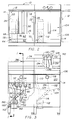
- Fig. 1 is a somewhat schematic, side elevation in section of a preferred embodiment of the present invention, taken at line 1-1 of Fig. 3;
- Fig. 2 is a top plan view of the pasta cooker shown in Fig. 1;
- Fig. 3 is a front elevation of the pasta cooker shown in Fig. 1, with portions broken away to reveal interior structure; and
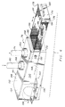
- Fig. 4 is an exploded, perspective view of the screen box of the pasta cooker of Fig. 1.
- As shown in Fig. 1, the preferred embodiment of the pasta cooker of the present invention, generally designated 10, includes an
open tank 12 which is supported within acabinet 14. Thetank 12 includes afront wall 16, arear wall 18 andside walls 20, 22 (see Fig. 2). Thetank 12 includes abottom wall 24 having downwardly convergingsurfaces flat surface 30. -
Heat tubes front wall 16 andrear wall 18, and receiveburner castings gas burner system 44. Thegas burner system 44 includes agas valve 46 which is manually adjustable byknob 48 and directs gas fromfeed line 50 tosupply lines 52 which are connected to the burner castings 38-42. Athermostatic sensor 54 is mounted within thetank 12 ontube 32 and is connected tovalve 46 bywires 56. Thethermostatic sensor 54 includes a high limit shut off which closes thevalve 46 when the temperature within the tank reaches 225¨ F, which would indicate that thetank 12 has boiled dry. Thesensor 54 also includes a component which detects temperatures for set points corresponding to: boil and simmer. Consequently, it is not necessary for an operator to adjust a gas valve constantly during cooking to maintain a particular temperature. - A
trough 58 is positioned adjacent to thetank 12, and, as shown Fig. 2, is coextensive with thefront wall 16. Thetrough 58 includes a forwardly and downwardly slopingbottom wall 60, aflat base wall 62 which includes adrain opening 64, afront wall 66 andopposing side walls drain opening 64 is connected to astub tube 72, which, in turn, is connected to a flexiblehigh temperature hose 74.Hose 74 is connected at a lower end to a screen box, generally designated 76. - The
tank 12 also includes adrain opening 78 which is formed in theflat surface 30 of thebottom wall 24 and is connected to a drain tube, generally designated 80.Drain tube 80 includes adrain valve 82 which is actuated by ahandle 84 that extends forwardly to the front of the cabinet, so that it may be actuated by an operator of thecooker 10.Drain tube 80 also is connected to drain intoscreen box 76. - The
cabinet 14 supports afill valve 86 which is connected to hotwater feed line 88 and supplies hot water to thetank 12 by a hotwater fill line 90. Hotwater fill line 90 is connected to afill opening 92 located at the bottom of therear wall 18. - The rear of the
cabinet 14 includes asupport stand 94 having atransverse channel 96 with anopening 98 shaped to receive thetongue 100 of an openmesh pasta basket 102. Accordingly, thepasta basket 102 may be suspended from the support stand 94 above thetank 12 by inserting thetongue 100 into the opening 98. - In the preferred embodiment of the
cooker 10, as best shown in Figs. 2 and 3, arinsing tank 104 is supported within thecabinet 14 adjacent to thetank 12.Rinsing tank 104 is substantially identical totank 12 in construction; however, it lacks thetubes gas burner system 34. In the embodiment shown, therinse tank 104 also includes atrough 106 having adrain opening 108 that is connected to adrain tube 110 that drains into asecond screen box 112.Tank 104 also includes adrain opening 114 which is connected to a valveddrain tube 116 that empties intoscreen box 112.Drain tubes screen box 112 are substantially identical in construction and components to their counterparts associated to tank 112. - Cold water fill valve 118 is mounted on the
front panel 120 of thecabinet 14 adjacent totank 104, and is supplied by coldwater supply line 122. Valve 118 is connected to a fill opening 124 intank 104 by cold water fill line 126. - The support stand 94 adjacent to
tank 104 includes a sprayer system, generally designated 128.Sprayer system 128 includes hot andcold water valves water supply lines Valves flexible sprayer hose 138 which terminates in aspray nozzle 140. The knobs of thevalves spray nozzle 140 are mounted on aninclined panel 142. - As shown in Fig. 4, the screen box 76 (which is substantially identical in construction to screen box 112) includes a
housing 144 and aremovable drawer 146. Thehousing 144 includes atop wall 148,opposing side walls rear wall 154, abottom wall 156 which is inclined downwardly and rearwardly, and afront wall 158.Side wall 150 includes an L-shaped channel 160 which is attached to a tubular channel 162 (see Fig. 3) that is integral with thecabinet 14. Thetop wall 148 includesnipples drain hose 74 from thetrough 58 and thedrain tube 80 from thetank 12. The connections are sufficiently more to provide a vacuum break.Side walls Front wall 158 includes arectangular opening 172 which is shaped to receive thedrawer 146. -
Drawer 146 includes an imperforatefront face 174 which includes a pair of opposingside flanges handle 180.Drawer 146 also includesside walls bottom wall 186, andrear wall 188. Walls 182-188 preferably are made of stainless steel which is perforated such that it is a minimum of 60% open. - The
front face 174 and side flanges 176-178 are shaped such that the side flanges overlies theside walls housing 144 when the drawer is inserted therein. Theside walls side flanges 176, 178 (only onelug 194 being shown in Fig. 4, it being understood thatflange 178 carries an identical lug). Overcenter buckles 190, 192 operate to positively mechanically secure thedrawer 146 to thehousing 144 during operation. - The
drawer 146 is positioned directly beneath thenipples trough 58 andtank 12 flows directly into thedrawer 146 and the perforated 182-186 filter any particulates carried out of the drain water. Therear wall 154 includes adrain opening 194 which is connected to a conventional drain line 196 (see Fig. 1). - The operation of the
pasta cooker 10 is as follows. Initially, the operator actuates fillvalve 86 which permits hot water to flow throughlines fill opening 92 to filltank 12 with hot water. Whentank 12 becomes sufficiently filled, thegas burner system 34 is actuated, andburners tank 12. Thecontrol knob 48 is set for boil, and the water is heated. When thewater 194 begins boiling, thebasket 102, filled with uncooked--or partially cooked-- pasta is placed in thetank 12 and rests upon thetubes - As the pasta cooks, the
upper surface 196 of thewater 194 begins to foam with starch. This starch foam begins washing from thetank 12 intotrough 58, wherein it flows downbottom wall 60 tobase wall 62. After a period of boiling, it is preferable to actuate the fill valve to provide a constant inflow of hot water throughopening 92, which causes a small amount ofwater 194 to continually flow fromtank 12 totrough 58. Since the starch foam floats on theupper surface 196 of thewater 194, the starch foam is continually removed from the water in the tank. Once in thetrough 58, the water and foam flows through thedrain opening 64,drain tube 74, and into thescreen box 76. - Once the water has flowed into
screen box 76, it flows through thedrawer 146 and the perforated walls 182-188 of the drawer filter out and retain the foam and any pasta particles entrained in the water. The remaining water flows through walls 182-188 and is conveyed rearwardly along thehousing 144 by flowing downwardly and rearwardlyinclined bottom wall 156 to thedrain opening 194, at which time the drain water enters the conventional drain pipe and is conveyed to a sanitary sewer system. - Once the pasta in
basket 102 has been sufficiently cooked, thebasket 102 is lifted fromtank 12 and may be suspended onchannel 196, in the manner previously described to allow water to drain from it. Thebasket 102 is then placed intank 104, which may be filled with cold water by means of valve 118 andwater supply lines 122, 126. Alternately, or in addition, the pasta can be chilled by spraying it with water fromspray nozzle 140, in which case thevalves - After the cooking period has been completed,
valve 82 is actuated to drain thetank 12 of water. The drain water travels throughdrain tube 80 and intoscreen box 76 throughnipple 166. Drain water fromtank 12 flows through the perforated walls 182-186 ofdrawer 146 and the particles of pasta, any other large contaminants, and any foam in such water is contained withindrawer 146; the filtered water then flows alongbottom wall 156 and outdrain opening 194. - When the draining procedure for
tank 12 has been completed,drawer 146 may be removed and cleaned, preferably by scraping material from the perforated walls 182-188 into a waste container. It is also preferable to perform such adrawer 146 cleaning procedure intermittently during the cooking procedure, in which case it is preferable to have at least twodrawers 146 so that they may be alternated to provide continuous filtering of drain water. - Similarly, after the cooking procedure has been completed,
tank 104 is drained by actuating the valve ondrain line 116 and draining the cold water throughscreen box 112, where a filtering and draining process occurs which is substantially identical to that forscreen box 76. Once bothtanks spray nozzle 140. The temperature of such cleaning water may be adjusted appropriately byvalves - It is also within the scope of the present invention to provide an array or battery of tanks, each being constructed as either
tank tanks 12, positioned on either side of atank 104, so that thesingle tank 104 could provide a draining and chilling function for pasta being cooked in each of thetanks 12. Such an arrangement is shown in phantom in Fig. 2 wherein a second tank 12' is positionedopposite tank 104 fromtank 12 - While the forms of apparatus herein described constitute preferred embodiments of this invention, it is to be understood that the invention is not limited to these precise forms of apparatus, and that changes may be made therein without departing from the scope of the invention.
- The features disclosed in the foregoing description, in the following claims and/or in the accompanying drawings may, both separately and in any combination thereof, be material for realising the invention in diverse forms thereof.
Claims (25)
- An apparatus for cooking pasta comprising:
means forming a tank for holding water;
means for heating water in said tank; and
means forming a trough communicating with said tank means, said trough means being positioned to receive and collect starch foam from an upper surface of water in said tank means, whereby starch foam generated by boiling of pasta in said tank means is automatically and continually removed from an upper surface of water in said tank means. - The apparatus of claim 1 further comprising drain means for removing starch foam and water from said trough means.
- The apparatus of claim 1 further comprising means for filling said tank means with water.
- The apparatus of claim 3 wherein said filling means includes means for continuously filling said tank means with water such that an upper surface of said water in said tank means is substantially co-extensive with an upper edge of said trough means, whereby starch foam floating on said upper surface continuously washes into said trough means.
- The apparatus of claim 2 further comprising screen means for receiving and capturing pasta starch entrained in water received by said trough means.
- The apparatus of claim 5 further comprising means for draining said tank means, said draining means being connected to direct water from said tank means to said screen means.
- The apparatus of claim 5 wherein said screen means includes a screen connected to said trough means to receive water therefrom.
- The apparatus of claim 7 wherein said screen means includes a chamber housing said screen, said chamber being connected to receive water from said trough means.
- The apparatus of claim 8 further comprising means interconnecting said housing and said drain means.
- The apparatus of claim 9 wherein said chamber is shaped to enclose said screen substantially entirely, and said screen is shaped to be removable from said housing.
- The apparatus of claim 10 wherein said housing is shaped to receive overflow from said screen in the event said screen becomes clogged with starch.
- The apparatus of claim 11 wherein said housing includes a floor sloping downwardly and rearwardly from said screen; and a drain opening positioned rearwardly of said screen.
- The apparatus of claim 1 further comprising means for spraying water on pasta in said tank means.
- The apparatus of claim 13 wherein said spraying means includes a spray nozzle and a flexible hose connected to a source of water.
- The apparatus of claim 14 further comprising second tank means, positioned adjacent to said tank means, for receiving pasta cooked in said tank means, whereby cooked pasta in said second tank means is sprayed with water by said spraying means.
- A method of cooking pasta comprising the steps of:
boiling water in tank means;
placing pasta in said water; and
continuously removing starch foam from an upper surface of said water during said boiling step. - The method of claim 16 wherein said removing step includes the step of continuously adding water to said tank means during said boiling step to cause said water to continuously wash from said tank means into trough means positioned adjacent to said tank means.
- The method of claim 17 further comprising the step of draining said trough means.
- The method of claim 18 wherein said draining step includes the step of filtering water drained from said trough means, whereby starch particles entrained in said drained water are removed therefrom.
- The method of claim 19 wherein said draining step includes the step of continuously draining said water from said trough means during said boiling step.
- An apparatus for cooking pasta comprising:
a cabinet;
means supported in said cabinet forming a boiling tank;
means for heating water in said boiling tank;
means supported in said cabinet forming a rinsing tank, said rinsing tank means being positioned adjacent to said boiling tank;
means associated with said rinsing tank means for introducing cold water to the contents of said rinsing tank means, whereby pasta is boiled in said boiling tank means and is chilled and rinsed in said rinsing tank means. - The apparatus of claim 21 wherein said cold water introducing means includes means for spraying cold water on the contents of said rinsing tank means.
- The apparatus of claim 22 wherein said cold water spraying means includes a flexible,- retractable hose, said hose having sufficient length such that said spraying means can reach said boiling tank to effect rinsing and cleaning thereof.
- The apparatus of claim 23 wherein said cabinet includes a rear wall supporting said spraying means adjacent to said rinsing tank means.
- The apparatus of claim 21 further comprising second boiling tank means, supported within said cabinet and positioned adjacent to said rinsing tank means, for boiling pasta, wherein an array of tanks is formed such that said rinsing tank means is positioned to receive cooked pasta from both of said boiling tank means.
Applications Claiming Priority (2)
| Application Number | Priority Date | Filing Date | Title |
|---|---|---|---|
| US14111793A | 1993-10-21 | 1993-10-21 | |
| US141117 | 1993-10-21 |
Publications (3)
| Publication Number | Publication Date |
|---|---|
| EP0649623A2 true EP0649623A2 (en) | 1995-04-26 |
| EP0649623A3 EP0649623A3 (en) | 1995-09-27 |
| EP0649623B1 EP0649623B1 (en) | 1998-08-12 |
Family
ID=22494232
Family Applications (1)
| Application Number | Title | Priority Date | Filing Date |
|---|---|---|---|
| EP94307616A Expired - Lifetime EP0649623B1 (en) | 1993-10-21 | 1994-10-18 | Pasta cooker |
Country Status (8)
| Country | Link |
|---|---|
| US (1) | US5609093A (en) |
| EP (1) | EP0649623B1 (en) |
| JP (1) | JPH07177969A (en) |
| AU (1) | AU676607B2 (en) |
| CA (1) | CA2118453C (en) |
| DE (1) | DE69412416T2 (en) |
| DK (1) | DK0649623T3 (en) |
| NO (1) | NO306924B1 (en) |
Cited By (2)
| Publication number | Priority date | Publication date | Assignee | Title |
|---|---|---|---|---|
| US11382450B2 (en) * | 2018-06-18 | 2022-07-12 | Electrolux Professional S.P.A. | Pasta cooking appliance |
| EP4201225A1 (en) | 2021-12-22 | 2023-06-28 | Pastificio della Mamma | Process for making laminated dough with peripheral starch removal |
Families Citing this family (20)
| Publication number | Priority date | Publication date | Assignee | Title |
|---|---|---|---|---|
| EP0773735B1 (en) * | 1994-08-01 | 2000-02-16 | Hakvoort Horeca B.V. | Frying device |
| IT241559Y1 (en) * | 1996-06-20 | 2001-05-09 | Electrolux Zanussi Grandi Impi | GAS FRYER WITH PERFECTED TURBULATOR |
| JP2995549B2 (en) * | 1997-05-12 | 1999-12-27 | 平野 英雄 | Stocking pot |
| US6063421A (en) * | 1998-07-15 | 2000-05-16 | Barravecchio; Joseph | Method and apparatus for rethermalizing pre-cooked food portions |
| FR2800442B1 (en) * | 1999-11-02 | 2002-07-26 | Damon Raymond Jacques Marcel | GAS-HEATED MOBILE BAIN - MARIE POT |
| US6192791B1 (en) | 1999-11-15 | 2001-02-27 | Maytag Corporation | Boiling sink cooking system for a kitchen |
| US7303776B2 (en) * | 2002-04-22 | 2007-12-04 | Restaurant Technology, Inc. | Automated food processing system and method |
| US8707857B2 (en) | 2005-08-08 | 2014-04-29 | Ronald M. Popeil | Cooking device to deep fat fry foods |
| CA2568468C (en) * | 2006-11-17 | 2015-01-20 | Paul M. Kehoe | Electric cooker |
| US9320388B2 (en) * | 2009-11-15 | 2016-04-26 | Legupro Ab | Liquid movement and control within a container for food preparation |
| DE102010000327A1 (en) | 2010-02-05 | 2011-08-11 | Maier, Max, 71636 | Pasta cooker |
| EP2703739B1 (en) * | 2012-08-31 | 2015-07-29 | Electrolux Home Products Corporation N.V. | A cooking oven with an oven cavity and a steam cooking arrangement |
| US10400105B2 (en) | 2015-06-19 | 2019-09-03 | The Research Foundation For The State University Of New York | Extruded starch-lignin foams |
| US10736463B2 (en) * | 2016-03-17 | 2020-08-11 | Henny Penny Corporation | Multiport/rotary valve sensor using hall effect control |
| IT201800004840A1 (en) * | 2018-04-24 | 2019-10-24 | COOKING PROCEDURE | |
| CN110870688B (en) | 2018-08-31 | 2021-06-15 | 百睿达科技有限公司 | Automatic cooking machine |
| JP6746256B1 (en) * | 2019-06-21 | 2020-08-26 | 株式会社ソディック | Weighing device |
| IT202000030416A1 (en) * | 2020-12-10 | 2022-06-10 | A M T S R L | "KETTLES WITH ENERGY RECOVERY" |
| US12075945B1 (en) * | 2022-12-07 | 2024-09-03 | Sidney Tracy Highnote | High speed convection fryer |
| KR102766721B1 (en) * | 2024-09-10 | 2025-02-13 | 주식회사 클린에이 | A device that reduces carbohydrates in grains such as rice or brown rice |
Family Cites Families (27)
| Publication number | Priority date | Publication date | Assignee | Title |
|---|---|---|---|---|
| US527400A (en) * | 1894-10-16 | Cut-off and strainer attachment for rain-water spouts | ||
| US677773A (en) * | 1900-07-16 | 1901-07-02 | Ora Burbridge | Filter. |
| US2287396A (en) * | 1941-05-09 | 1942-06-23 | Joe Lowe Corp | Fat leveling system |
| GB661582A (en) * | 1949-03-28 | 1951-11-21 | John Miller Anderson | Improvements in electrically heated frying stoves |
| GB668613A (en) * | 1949-08-16 | 1952-03-19 | Hermann Oberlaender | Improvements relating to frying apparatus |
| US3107601A (en) * | 1958-09-02 | 1963-10-22 | Richard L Longmire | Filtration and recirculation system for deep fat cooking apparatus |
| US2978975A (en) * | 1958-11-10 | 1961-04-11 | Rossi Peter | Apparatus for cooking farinaceous materials |
| US3363541A (en) * | 1967-01-25 | 1968-01-16 | Anetsberger Bros Inc | Crumb collecting deep fat fryer |
| US3839951A (en) * | 1968-07-30 | 1974-10-08 | Parkson Ind Equipment Co | Apparatus for cooking comestibles |
| US3685433A (en) * | 1971-04-14 | 1972-08-22 | Cecil R Cunningham | Deep fat fryer assembly |
| US3785970A (en) * | 1971-12-27 | 1974-01-15 | Stanadyne Inc | Water separator |
| US3735693A (en) * | 1972-02-23 | 1973-05-29 | Kentucky Fried Chicken Co | Hot oil recirculating cooking system |
| US4084492A (en) * | 1975-10-08 | 1978-04-18 | Kfc Corporation | System for providing like cooking medium volume in successive cooking cycles |
| US4420006A (en) * | 1976-12-23 | 1983-12-13 | The Frymaster Corporation | Spray cleaning system for frying apparatus |
| IT1082147B (en) * | 1977-07-26 | 1985-05-21 | Nilma Di Nobili Pietro | MACHINE FOR COOKING FOOD PASTA, RICE AND SIMILAR FOOD PRODUCTS |
| US4495072A (en) * | 1983-02-25 | 1985-01-22 | Yardney Corporation | Filter screen device |
| JPS60139222A (en) * | 1983-12-28 | 1985-07-24 | リコ−機器株式会社 | Fryer |
| NL8401038A (en) * | 1984-04-02 | 1985-11-01 | Atag Bv Apparatenfab | DEEP FRYER. |
| IT1184698B (en) * | 1984-04-12 | 1987-10-28 | Giovanni Barbieri | FOOD COOKING APPLIANCE |
| US4623544A (en) * | 1984-08-03 | 1986-11-18 | Highnote Sidney T | Constant temperature fryer/cooker assembly |
| US4597325A (en) * | 1985-04-12 | 1986-07-01 | Yankee Noodle Dandy, Inc. | Rotary cooking apparatus |
| FR2596250B3 (en) * | 1986-03-27 | 1988-02-26 | Aldeguer Rene | DEVICE FOR COOKING PASTA |
| EP0428763B1 (en) * | 1989-11-18 | 1993-01-20 | Frisco-Findus Ag | Blanching pasta |
| US5313876A (en) * | 1991-05-17 | 1994-05-24 | The Frymaster Corporation | Spaghetti cooking system |
| US5228985A (en) * | 1991-06-13 | 1993-07-20 | Laroche Filter Systems, Inc. | Cooking oil filtering apparatus |
| US5184539A (en) * | 1991-12-02 | 1993-02-09 | Meito Corporation | Fryer |
| US5247876A (en) * | 1993-01-25 | 1993-09-28 | Wilson Mark L | Deep fryer and filtration system |
-
1994
- 1994-10-18 DE DE69412416T patent/DE69412416T2/en not_active Expired - Fee Related
- 1994-10-18 EP EP94307616A patent/EP0649623B1/en not_active Expired - Lifetime
- 1994-10-18 DK DK94307616T patent/DK0649623T3/en active
- 1994-10-19 CA CA002118453A patent/CA2118453C/en not_active Expired - Fee Related
- 1994-10-19 AU AU75921/94A patent/AU676607B2/en not_active Ceased
- 1994-10-20 JP JP6255465A patent/JPH07177969A/en active Pending
- 1994-10-20 NO NO943986A patent/NO306924B1/en not_active IP Right Cessation
-
1995
- 1995-06-26 US US08/494,038 patent/US5609093A/en not_active Expired - Lifetime
Cited By (4)
| Publication number | Priority date | Publication date | Assignee | Title |
|---|---|---|---|---|
| US11382450B2 (en) * | 2018-06-18 | 2022-07-12 | Electrolux Professional S.P.A. | Pasta cooking appliance |
| EP4201225A1 (en) | 2021-12-22 | 2023-06-28 | Pastificio della Mamma | Process for making laminated dough with peripheral starch removal |
| BE1030078A1 (en) | 2021-12-22 | 2023-07-14 | Pastificio Della Mamma | Process for manufacturing laminated pasta with elimination of peripheral starch |
| BE1030078B1 (en) * | 2021-12-22 | 2023-07-19 | Pastificio Della Mamma | Process for manufacturing laminated pasta with elimination of peripheral starch |
Also Published As
| Publication number | Publication date |
|---|---|
| DE69412416T2 (en) | 1998-12-24 |
| CA2118453A1 (en) | 1995-04-22 |
| NO943986D0 (en) | 1994-10-20 |
| NO306924B1 (en) | 2000-01-17 |
| AU7592194A (en) | 1995-05-11 |
| NO943986L (en) | 1995-04-24 |
| DK0649623T3 (en) | 1999-05-10 |
| US5609093A (en) | 1997-03-11 |
| EP0649623B1 (en) | 1998-08-12 |
| JPH07177969A (en) | 1995-07-18 |
| DE69412416D1 (en) | 1998-09-17 |
| EP0649623A3 (en) | 1995-09-27 |
| CA2118453C (en) | 1999-06-08 |
| AU676607B2 (en) | 1997-03-13 |
Similar Documents
| Publication | Publication Date | Title |
|---|---|---|
| US5609093A (en) | Pasta cooker | |
| US5452648A (en) | Screen box for a pasta cooker | |
| US4324173A (en) | Filter system for frying apparatus | |
| US4420006A (en) | Spray cleaning system for frying apparatus | |
| US4210123A (en) | Filter system for frying apparatus | |
| US4768426A (en) | Oil filter apparatus and method for deep oil pressure cooking apparatus | |
| US3648595A (en) | Food fryer with continuously filtered cooking oil | |
| US4195667A (en) | Solenoid valve with safety control circuit | |
| JPH0368325A (en) | Device for dish-washing machine | |
| US3735693A (en) | Hot oil recirculating cooking system | |
| US4622135A (en) | Grease filtering apparatus | |
| CA3052633C (en) | Rotisserie oven with improved trap system | |
| JP7174582B2 (en) | Heating cooker with cleaning function for the cooking chamber | |
| EP1516570B1 (en) | Improved filter system for a deep fat fryer | |
| US4259567A (en) | Positive reset safety control circuit for frying apparatus | |
| US4210177A (en) | Positive reset safety control system for frying apparatus | |
| US5660194A (en) | Washing system for pre-wash tanks | |
| US3717159A (en) | Pot washer and sterilizer | |
| US3463078A (en) | Deep fat frying apparatus | |
| JP3318573B2 (en) | Pot with aku removal function | |
| US2760645A (en) | Apparatus for purifying edible oils | |
| EP0676511B1 (en) | Ventilation ceiling with integral air filter units | |
| CN223275328U (en) | Electric fryer with water circulation filtration | |
| KR910001274Y1 (en) | A pan cleaner | |
| JPH0910160A (en) | Dish washing machine |
Legal Events
| Date | Code | Title | Description |
|---|---|---|---|
| PUAI | Public reference made under article 153(3) epc to a published international application that has entered the european phase |
Free format text: ORIGINAL CODE: 0009012 |
|
| AK | Designated contracting states |
Kind code of ref document: A2 Designated state(s): BE CH DE DK FR GB IT LI NL SE |
|
| PUAL | Search report despatched |
Free format text: ORIGINAL CODE: 0009013 |
|
| AK | Designated contracting states |
Kind code of ref document: A3 Designated state(s): BE CH DE DK FR GB IT LI NL SE |
|
| 17P | Request for examination filed |
Effective date: 19950926 |
|
| 17Q | First examination report despatched |
Effective date: 19961025 |
|
| GRAG | Despatch of communication of intention to grant |
Free format text: ORIGINAL CODE: EPIDOS AGRA |
|
| GRAG | Despatch of communication of intention to grant |
Free format text: ORIGINAL CODE: EPIDOS AGRA |
|
| GRAH | Despatch of communication of intention to grant a patent |
Free format text: ORIGINAL CODE: EPIDOS IGRA |
|
| GRAH | Despatch of communication of intention to grant a patent |
Free format text: ORIGINAL CODE: EPIDOS IGRA |
|
| ITF | It: translation for a ep patent filed | ||
| GRAA | (expected) grant |
Free format text: ORIGINAL CODE: 0009210 |
|
| AK | Designated contracting states |
Kind code of ref document: B1 Designated state(s): BE CH DE DK FR GB IT LI NL SE |
|
| REG | Reference to a national code |
Ref country code: CH Ref legal event code: NV Representative=s name: ISLER & PEDRAZZINI AG Ref country code: CH Ref legal event code: EP |
|
| REF | Corresponds to: |
Ref document number: 69412416 Country of ref document: DE Date of ref document: 19980917 |
|
| ET | Fr: translation filed | ||
| REG | Reference to a national code |
Ref country code: DK Ref legal event code: T3 |
|
| PLBE | No opposition filed within time limit |
Free format text: ORIGINAL CODE: 0009261 |
|
| STAA | Information on the status of an ep patent application or granted ep patent |
Free format text: STATUS: NO OPPOSITION FILED WITHIN TIME LIMIT |
|
| 26N | No opposition filed | ||
| PGFP | Annual fee paid to national office [announced via postgrant information from national office to epo] |
Ref country code: FR Payment date: 20011002 Year of fee payment: 8 |
|
| PGFP | Annual fee paid to national office [announced via postgrant information from national office to epo] |
Ref country code: SE Payment date: 20011003 Year of fee payment: 8 |
|
| PGFP | Annual fee paid to national office [announced via postgrant information from national office to epo] |
Ref country code: GB Payment date: 20011004 Year of fee payment: 8 Ref country code: DK Payment date: 20011004 Year of fee payment: 8 Ref country code: DE Payment date: 20011004 Year of fee payment: 8 Ref country code: CH Payment date: 20011004 Year of fee payment: 8 |
|
| PGFP | Annual fee paid to national office [announced via postgrant information from national office to epo] |
Ref country code: NL Payment date: 20011009 Year of fee payment: 8 |
|
| PGFP | Annual fee paid to national office [announced via postgrant information from national office to epo] |
Ref country code: BE Payment date: 20011025 Year of fee payment: 8 |
|
| REG | Reference to a national code |
Ref country code: GB Ref legal event code: IF02 |
|
| PG25 | Lapsed in a contracting state [announced via postgrant information from national office to epo] |
Ref country code: GB Free format text: LAPSE BECAUSE OF NON-PAYMENT OF DUE FEES Effective date: 20021018 |
|
| PG25 | Lapsed in a contracting state [announced via postgrant information from national office to epo] |
Ref country code: SE Free format text: LAPSE BECAUSE OF NON-PAYMENT OF DUE FEES Effective date: 20021019 |
|
| PG25 | Lapsed in a contracting state [announced via postgrant information from national office to epo] |
Ref country code: LI Free format text: LAPSE BECAUSE OF NON-PAYMENT OF DUE FEES Effective date: 20021031 Ref country code: DK Free format text: LAPSE BECAUSE OF NON-PAYMENT OF DUE FEES Effective date: 20021031 Ref country code: CH Free format text: LAPSE BECAUSE OF NON-PAYMENT OF DUE FEES Effective date: 20021031 Ref country code: BE Free format text: LAPSE BECAUSE OF NON-PAYMENT OF DUE FEES Effective date: 20021031 |
|
| BERE | Be: lapsed |
Owner name: *HOBART CORP. Effective date: 20021031 |
|
| PG25 | Lapsed in a contracting state [announced via postgrant information from national office to epo] |
Ref country code: NL Free format text: LAPSE BECAUSE OF NON-PAYMENT OF DUE FEES Effective date: 20030501 Ref country code: DE Free format text: LAPSE BECAUSE OF NON-PAYMENT OF DUE FEES Effective date: 20030501 |
|
| EUG | Se: european patent has lapsed | ||
| REG | Reference to a national code |
Ref country code: DK Ref legal event code: EBP |
|
| GBPC | Gb: european patent ceased through non-payment of renewal fee |
Effective date: 20021018 |
|
| REG | Reference to a national code |
Ref country code: CH Ref legal event code: PL |
|
| PG25 | Lapsed in a contracting state [announced via postgrant information from national office to epo] |
Ref country code: FR Free format text: LAPSE BECAUSE OF NON-PAYMENT OF DUE FEES Effective date: 20030630 |
|
| NLV4 | Nl: lapsed or anulled due to non-payment of the annual fee |
Effective date: 20030501 |
|
| REG | Reference to a national code |
Ref country code: FR Ref legal event code: ST |
|
| PG25 | Lapsed in a contracting state [announced via postgrant information from national office to epo] |
Ref country code: IT Free format text: LAPSE BECAUSE OF NON-PAYMENT OF DUE FEES Effective date: 20051018 |