EP0652430A1 - Verfahren und Vorrichtung zur Bestimmung des Russgehaltes von Kautschukmischungen - Google Patents
Verfahren und Vorrichtung zur Bestimmung des Russgehaltes von Kautschukmischungen Download PDFInfo
- Publication number
- EP0652430A1 EP0652430A1 EP93113036A EP93113036A EP0652430A1 EP 0652430 A1 EP0652430 A1 EP 0652430A1 EP 93113036 A EP93113036 A EP 93113036A EP 93113036 A EP93113036 A EP 93113036A EP 0652430 A1 EP0652430 A1 EP 0652430A1
- Authority
- EP
- European Patent Office
- Prior art keywords
- concentration
- carbon black
- measurement
- carbon
- measurements
- Prior art date
- Legal status (The legal status is an assumption and is not a legal conclusion. Google has not performed a legal analysis and makes no representation as to the accuracy of the status listed.)
- Granted
Links
- 239000006229 carbon black Substances 0.000 title claims abstract description 71
- 238000000034 method Methods 0.000 title claims abstract description 42
- 238000009826 distribution Methods 0.000 title claims abstract description 11
- 150000001875 compounds Chemical class 0.000 title claims description 43
- 239000000463 material Substances 0.000 title claims description 24
- 229910052799 carbon Inorganic materials 0.000 claims abstract description 48
- OKTJSMMVPCPJKN-UHFFFAOYSA-N Carbon Chemical compound [C] OKTJSMMVPCPJKN-UHFFFAOYSA-N 0.000 claims abstract description 45
- 230000003595 spectral effect Effects 0.000 claims abstract description 45
- 238000011088 calibration curve Methods 0.000 claims abstract description 25
- 238000005259 measurement Methods 0.000 claims description 101
- 210000002381 plasma Anatomy 0.000 claims description 57
- 238000004458 analytical method Methods 0.000 claims description 52
- 230000005855 radiation Effects 0.000 claims description 21
- 239000004615 ingredient Substances 0.000 claims description 20
- 239000000203 mixture Substances 0.000 claims description 20
- 239000000470 constituent Substances 0.000 claims description 16
- 230000003287 optical effect Effects 0.000 claims description 8
- 239000006185 dispersion Substances 0.000 claims description 6
- 238000004519 manufacturing process Methods 0.000 claims description 6
- 230000001747 exhibiting effect Effects 0.000 claims description 5
- 238000002156 mixing Methods 0.000 claims description 4
- 238000003860 storage Methods 0.000 claims description 4
- 238000001514 detection method Methods 0.000 claims description 2
- 238000000354 decomposition reaction Methods 0.000 claims 1
- 238000002344 laser microprobe spectroscopy Methods 0.000 claims 1
- 239000011159 matrix material Substances 0.000 abstract description 2
- 230000015556 catabolic process Effects 0.000 abstract 1
- 239000002131 composite material Substances 0.000 abstract 1
- 238000004611 spectroscopical analysis Methods 0.000 abstract 1
- 238000011156 evaluation Methods 0.000 description 5
- VYPSYNLAJGMNEJ-UHFFFAOYSA-N silicon dioxide Inorganic materials O=[Si]=O VYPSYNLAJGMNEJ-UHFFFAOYSA-N 0.000 description 5
- 229910052710 silicon Inorganic materials 0.000 description 3
- 239000000377 silicon dioxide Substances 0.000 description 3
- XKRFYHLGVUSROY-UHFFFAOYSA-N Argon Chemical compound [Ar] XKRFYHLGVUSROY-UHFFFAOYSA-N 0.000 description 2
- 239000005864 Sulphur Substances 0.000 description 2
- 238000013461 design Methods 0.000 description 2
- 239000013307 optical fiber Substances 0.000 description 2
- 229910052760 oxygen Inorganic materials 0.000 description 2
- 238000002360 preparation method Methods 0.000 description 2
- 238000011158 quantitative evaluation Methods 0.000 description 2
- 150000003839 salts Chemical class 0.000 description 2
- 238000001228 spectrum Methods 0.000 description 2
- BPQQTUXANYXVAA-UHFFFAOYSA-N Orthosilicate Chemical compound [O-][Si]([O-])([O-])[O-] BPQQTUXANYXVAA-UHFFFAOYSA-N 0.000 description 1
- 235000021355 Stearic acid Nutrition 0.000 description 1
- NINIDFKCEFEMDL-UHFFFAOYSA-N Sulfur Chemical compound [S] NINIDFKCEFEMDL-UHFFFAOYSA-N 0.000 description 1
- 238000010521 absorption reaction Methods 0.000 description 1
- 239000003963 antioxidant agent Substances 0.000 description 1
- 229910052786 argon Inorganic materials 0.000 description 1
- 230000000712 assembly Effects 0.000 description 1
- 238000000429 assembly Methods 0.000 description 1
- QVGXLLKOCUKJST-UHFFFAOYSA-N atomic oxygen Chemical compound [O] QVGXLLKOCUKJST-UHFFFAOYSA-N 0.000 description 1
- 230000002238 attenuated effect Effects 0.000 description 1
- 239000011324 bead Substances 0.000 description 1
- 239000003738 black carbon Substances 0.000 description 1
- 229910052791 calcium Inorganic materials 0.000 description 1
- 238000004364 calculation method Methods 0.000 description 1
- 239000011203 carbon fibre reinforced carbon Substances 0.000 description 1
- 229910052681 coesite Inorganic materials 0.000 description 1
- 238000010924 continuous production Methods 0.000 description 1
- 229910052906 cristobalite Inorganic materials 0.000 description 1
- 239000013078 crystal Substances 0.000 description 1
- 230000001934 delay Effects 0.000 description 1
- 239000013536 elastomeric material Substances 0.000 description 1
- 239000004744 fabric Substances 0.000 description 1
- 239000000945 filler Substances 0.000 description 1
- 239000007789 gas Substances 0.000 description 1
- 229910052739 hydrogen Inorganic materials 0.000 description 1
- 239000011261 inert gas Substances 0.000 description 1
- 238000009533 lab test Methods 0.000 description 1
- 238000002536 laser-induced breakdown spectroscopy Methods 0.000 description 1
- 229910052751 metal Inorganic materials 0.000 description 1
- 238000012544 monitoring process Methods 0.000 description 1
- 229910052757 nitrogen Inorganic materials 0.000 description 1
- OQCDKBAXFALNLD-UHFFFAOYSA-N octadecanoic acid Natural products CCCCCCCC(C)CCCCCCCCC(O)=O OQCDKBAXFALNLD-UHFFFAOYSA-N 0.000 description 1
- 239000001301 oxygen Substances 0.000 description 1
- 239000004014 plasticizer Substances 0.000 description 1
- 239000000047 product Substances 0.000 description 1
- 230000001681 protective effect Effects 0.000 description 1
- 238000010074 rubber mixing Methods 0.000 description 1
- 239000011265 semifinished product Substances 0.000 description 1
- 238000000926 separation method Methods 0.000 description 1
- 239000010703 silicon Substances 0.000 description 1
- 235000012239 silicon dioxide Nutrition 0.000 description 1
- 239000008117 stearic acid Substances 0.000 description 1
- 229910052682 stishovite Inorganic materials 0.000 description 1
- 229910052717 sulfur Inorganic materials 0.000 description 1
- 239000004753 textile Substances 0.000 description 1
- 229910052905 tridymite Inorganic materials 0.000 description 1
- 238000012795 verification Methods 0.000 description 1
- 238000004073 vulcanization Methods 0.000 description 1
- 239000002699 waste material Substances 0.000 description 1
- 230000003313 weakening effect Effects 0.000 description 1
- 229910052725 zinc Inorganic materials 0.000 description 1
Images


Classifications
-
- G—PHYSICS
- G01—MEASURING; TESTING
- G01N—INVESTIGATING OR ANALYSING MATERIALS BY DETERMINING THEIR CHEMICAL OR PHYSICAL PROPERTIES
- G01N21/00—Investigating or analysing materials by the use of optical means, i.e. using sub-millimetre waves, infrared, visible or ultraviolet light
- G01N21/62—Systems in which the material investigated is excited whereby it emits light or causes a change in wavelength of the incident light
- G01N21/71—Systems in which the material investigated is excited whereby it emits light or causes a change in wavelength of the incident light thermally excited
- G01N21/718—Laser microanalysis, i.e. with formation of sample plasma
-
- G—PHYSICS
- G01—MEASURING; TESTING
- G01N—INVESTIGATING OR ANALYSING MATERIALS BY DETERMINING THEIR CHEMICAL OR PHYSICAL PROPERTIES
- G01N33/00—Investigating or analysing materials by specific methods not covered by groups G01N1/00 - G01N31/00
- G01N33/44—Resins; Plastics; Rubber; Leather
- G01N33/445—Rubber
Definitions
- the invention concerns a process for determining the carbon black concentration and distribution in rubber compounds and other carbon black-containing materials using pulsed laser beams focused on the material surface each of which produce a plasma with a radiation characteristic of the elements or molecules contained therein and divide the surface with their end regions into grid areas in which are located measuring points formed by the laser beam focuses, whereby the characteristic radiation, spectrally dispersed in the form of spectral lines or molecule bands, is measured by a detector unit and whereby from the concentration values calculated by reference to numerical ratios from the radiation intensities of selected elements/molecules with subsequent storage and allocated to the relevant measuring points, the concentration value curve at least over a section of the surface is established.
- the present invention lies in having perceived, as an essential part of a tyre manufacturing process, the technical problem of measuring the carbon (C) associated with the carbon black separate from the carbon of the rubber material, particularly and preferably based on different responses to ignition.
- a process and a device of the above mentioned kind are known from DE-A1-40 04 627; there, the surface to be examined is divided by a relative movement between itself and the end region of the laser beam into grid areas which are each assigned to a measuring point formed by the laser beam focus.
- the number of measuring points in one section of the surface can be adjusted in several gradations by altering in a suitable way the pulse frequency of the laser unit and/or the movement of the measuring point.
- the spacing between the measuring points assigned to the grid areas is relatively large or relatively small; this difference is due to the fact that the aim of investigating the degree of dispersion is to gain information on fine, small-area constituents such as for example salt crystals.
- the main components include a so-called "liner", that is a layer of elastomeric air-proof material, a carcass ply, a pair of annular metal elements, commonly referred to as bead cores, around which the opposite ends of the carcass ply are folded, as well as a pair of side pieces made of elastomeric material, which will constitute the sidewalls of the tire, extending over the carcass ply at laterally opposite positions.
- a so-called "liner” that is a layer of elastomeric air-proof material
- a carcass ply a pair of annular metal elements, commonly referred to as bead cores, around which the opposite ends of the carcass ply are folded, as well as a pair of side pieces made of elastomeric material, which will constitute the sidewalls of the tire, extending over the carcass ply at laterally opposite positions.
- the process to make the raw carcass substantially starts with the step, made in a so-called bambury, of preparing a rubber compound by mixing together at least a polymeric material with other ingredients, including carbon black, according to a prefixed quantitative ratios between said ingredients established in a given recipe; subsequently, from said compound at least a semi-finished component for said tyre is formed, like the tread band or the sidewalls or other rubber components.
- the forming devices like the extruders or calenders and so on, quite conveniently, are directly feeding the tyre building apparatus, on which a plurality of said semi-finished components are assembled together to build up a raw carcass, subsequently moulded and vulcanized in a curing mold.
- the advantage of this kind of process is that to minimize the need to store and manage a lot of semi-finished components, thus avoiding storage costs and possible problems in respect of feeding the requested components to the tyre building apparatus. It is then easy to appreciate the importance to check and measure, as soon as possible, and in real time during said building process, the composition of the corresponding compounds, i.e. the concentration and the degree of dispersion of the various ingredients, including the carbon black, in said compounds.
- the preferable time and place at which to have said check done is just when and where the compound is coming out of the bambury: by this way it is possible to immediately vary, on the basis of said detected information, the quantity of carbon black and other ingredients which are going to be loaded in the bambury to be mixed with said polymeric materials so as to fit the established composition for said compounds according to the prefixed quantitative ratios of ingredients of the given recipe, thus avoiding the preparation of possible batches of rubber compounds and/or a lot of semi-finished components not respondent to the prescribed provision.
- on-line process a manufacturing process in which the control on the product is made during the process.
- on-line process it has been proved to be of the greatest importance to check the concentration and distribution of the carbon black content in said tyre rubber compounds.
- the carbon black content influences above all the material hardness of such rubber compounds and therefore provides information on certain properties and the quality of the rubber compound to be examined. Determining the carbon black content has hitherto proved difficult insofar as this constituent can only be measured indirectly and only through laboratory tests, not allowed in an on-line process.
- the invention is based on the hypothesis that the carbon black in the rubber compounds of interest here is only very weakly bound and is therefore immediately liberated by laser beam bombardment, heated in the plasma of the ambient atmosphere and stimulated to radiate.
- the other evaporated constituents of the surface serving as specimen reach the plasma only relatively late, i.e. after around 1 ⁇ s; the carbon radiation resulting therefrom is weakened by absorption in the already existing carbon black cloud in front of the material surface, the weakening being the more pronounced the denser the carbon black cloud (i.e. the greater the carbon black concentration in the surface) is.
- the two aforementioned radiation processes can be separated from one another.
- the basic idea of the invention consists in determining the carbon black concentration by means of two laser pulses or laser pulse groups via two connected measurements of spectral intensities, namely a first measurement for a first plasma or a first plasma group and a second measurement for a second plasma or a second plasma group; related to the actuation of the particular laser pulse these two measurements will be carried out each with a fixed, different time delay relative to the respective time of actuation.
- the time delay is adjustable within the framework of the invention; however, from the point of view of maintaining consistent process conditions for the measurements of a specific measurement series it is fixed.
- the intensities of the spectral lines of carbon as reference element (I C ) and at least approximately all other analysis elements (I A.n ) in the relevant surface section are determined and from these the appurtenant intensity ratios (I A.n /I C ) of the spectral line of each analysis element to the spectral line of the reference element are determined.
- the intensities of the spectral lines of the reference element (I C' ) and at least one of the other analysis elements (I A.n' ) are determined and from these the appurtenant intensity ratio in each case is determined, this measurement being carried out with a shorter delay time than the appurtenant first measurement.
- this measurement being carried out with a shorter delay time than the appurtenant first measurement.
- the intensity ratio values from the first measurement determine the values of the appurtentant concentration ratios of at least approximately all analysis elements in the particular surface section and from these the value for the concentration of the reference element, from which the magnitude of the concentration of individual analysis elements can also be derived. Determining the concentration of the reference element requires that the concentration of all constituents in the surface amounts to 100% or differs only negligibly from this value or the balance of the concentration is sufficiently precisely known.
- the value of the concentration ratio between carbon black (c R ) and the particular analysis element (c A.n ) is determined and taking into account the previously calculated magnitude of the concentration of this analysis element the magnitude of the carbon black concentration is derived.
- the result of the second measurement is thus in each case evaluated taking into account the result of the appurtenant first measurement - which permits determination of the magnitude of the concentration of total carbon as well as that of selected or all other analysis elements in the surface - in such a way that the magnitude of the carbon black concentration (c R ) is derived from at least one intensity ratio value obtained by the second measurement, the concentration ratio value resulting from the appurtenant calibration curve and knowledge of the concentration of the analysis element, which concentration forms part of the aforementioned concentration ratio value.
- the calibration curves are obtained using standard specimens, i.e. specimens of known composition, with carbon being used as reference element (i.e. as internal standard) for rubber compounds, particularly for tyre compounds.
- reference element i.e. as internal standard
- the invention can fundamentally also be used to determine other constituents which are present in different forms and under laser beam bombardment behave differently like carbon black and the carbon assigned to the other constituents of the material.
- Rubber compounds for tyres consist of 70% to 85% carbon; up to 50% of the carbon can be assigned to the added carbon black.
- the carbon black-carbon can be distinguished from the total carbon by optical means (e.g. by means of a multichannel analyzer) and its concentration in the surface to be examined can thus be determined.
- the process is preferably configured such that the delay time after which the second measurement is carried out in each case is between 0.1 and 0.5 ⁇ s and/or the delay time for the first measurement is more than 0.5 to 5.0 ⁇ s (Claims 2, 3).
- the exposure time for identifying the produced plasma during the second measurement should be between 0.1 and 0.3 ⁇ s (Claim 4) and the exposure time for identifying the produced plasma during the first measurement should be between 0.2 and 10 ⁇ s Claim 5).
- the aforementioned exposure times show that the exposure time assigned to the first measurement should generally be greater (where necessary also considerably greater) than the exposure time assigned to the second measurement.
- the process is preferably carried out such that with both measurements - to the extent necessary for determining the carbon black concentration - the intensities of the same spectral lines of the reference element and the analysis elements are measured in each case (Claim 6).
- the carbon black concentration is determined by reference to the evaluation of the appurtenant first measurement, a multiple calculation can also be carried out on the basis of the known concentration values of different analysis elements and a mean value for the carbon black concentration can be derived in each case which is used as a basis for determining the concentration value curve (Claim 7).
- the invention can be configured in different ways, i.e. the plasmas for the first and the second measurements can be produced separately from one another in space and/or time (Claim 8). Separation in time can be effected - as for example in the case of the object of the previously cited DE-A1-40 04 627 - by such means that the plasmas for the first and the second measurements are produced consecutively in time by one and the same laser unit.
- Spatially separate plasmas can be produced by for example two laser pulses being actuated simultaneously in each case by two laser units; the two laser units can however also be switched such that the two laser pulses are produced at different times.
- two laser units for producing lasers pulses for the first and second measurements can also be arranged and switched in such a way that the two connected laser beam focuses impinge consecutively on one measuring point.
- each detector unit can be controlled with an adjustable time delay such that two measurements of the spectral intensities of separately produced plasmas are carried out each with a fixed, different time delay relative to the actuation time of the particular laser pulse; the time delay for the second measurement - by means of which the spectral line intensities of the reference element carbon (I C' ) and at least one of the other analysis elements (I A n' ) in the surface section can be ascertained - is smaller than that of the first measurement for determining the spectral line intensities of the reference element (I C ) and at least approximately all other analysis elements (I A.n ).
- calibration information which is based on reference measurements carried out with the time delay of both the first and the second measurement on specimens of known composition and which shows the magnitude of the concentration ratio of the other analysis elements or the at least one analysis element to the reference element as a function of the appurtenant intensity ratio values.
- the computer is configured such that from the intensity values of the first and second measurements ratio values corresponding to the calibration information are formed, and by comparison with the latter first the concentration of total carbon (c C ) and that of the at least one selected analysis element (c A.n ) and then by reference to the known concentration value (c A.n ) of at least one analysis element the magnitude of the carbon black concentration (c R ) are determined, the latter being used to establish the concentration value curve.
- the device can further be configured such that the laser pulses can be actuated relative to the surface such that the appurtenant plasmas for the first and the second measurements are produced separately from each other in space and/or in time (Claim 11).
- the facility to produce the laser beams may also exhibit several laser units (Claim 12).
- an embodiment is suitable by means of which several laser pulses can be accumulated.
- several laser pulses can be actuated in each case and from the intensity values of the first and the second plasma groups a mean value is formed in each case which forms the starting value for determining the concentration values (Claim 13).
- the device is preferably configured and designed such that the time delay for performing the first and the second measurements and the appurtenant exposure time for registering the produced plasma during the performance of the first and the second measurements are steplessly variable. It has proved advantageous to set the delay time for the two measurements between more than 0.5 and 5.0 ⁇ s and 0.1 and 0.5 ⁇ s respectively and the exposure time between 0.2 and 10 ⁇ s and 0.1 and 0.3 ⁇ s respectively.
- Such rubber slabs which are used as semifinished products in the manufacture of vehicle tyres, are generally composed of the following constituents: - Carbon black/carbon: 40% to 80% - ZnO: 1% to 10% - stearic acid: 0 to 4% - silica or silicate: 0 to 20% - sulphur: 0 to 6% - plasticizers: 0 to 40% - other constituents: (for example Co salts, antioxidants, etc.) 1 to 10% - other fillers: (different than carbon black or silica) 0 to 50%
- the movement of the end region 4a transverse to the longitudinal extension of the rubber slab 1 - indicated by a broken zigzag line 6 - is actuated by a deflector mirror 7; the latter performs a swivelling movement in the direction of the double arrow 8 about a swivel axis 7a.
- the plasma 4c occurring in each measuring point produces a radiation 3 characteristic of the elements or molecules contained in the plasma, which radiation is supplied to a spectrograph 10 in a way to be described.
- the plasma radiation is spectrally dispersed by means of a grating 11 and is identified in the form of individual spectral lines 9a (or possibly in the form of molecular bands) in time-staggered manner by a detector unit 12 configured as a diode array.
- the digitized spectrum is then transferred to a computer 13 for storage and evaluation.
- the intensity values obtained from the plasma radiation of each examined measuring point 4b are used to determine the concentration of carbon and selected analysis elements in the surface and from that the appurtenant carbon black concentration.
- the intensities of the spectral lines of the reference element (I C' ) and at least one of the other analysis elements (I A.n' ) are determined and from them in each case the appurtenant intensity ratio is determined.
- the exposure times t B1 and t B2 of the detector, during which the produced plasma is observed and analyzed in the performance of the first and second measurements, are 10 ⁇ s and 0.2 ⁇ s respectively.
- the quantitative evaluation of the results of the first and the second measurements is carried out by reference to the calibration information in calibration curves obtained from standard specimens, i.e. from specimens of known composition, using the delay times t V1 and t V2 and the exposure times t B1 , t B2 of the first and second measurements.
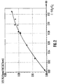
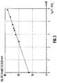
- the calibration curves show the magnitude of the previously mentioned intensity ratios I A.n /I C of the spectral line of each analysis element to the spectral line of the reference element and the intensity ratio I C' /I A.n' of the spectral line of the reference element to the spectral line of the at least one selected analysis element as a function of the appurtenant concentration ratio values c A.n /c C and C R (for the carbon black concentration)/c A.n .
- I A.n /I C f(c A.n /c C )
- the appurtenant concentration ratio values can be determined and from these, subject to the condition that the concentration values of all analysis elements and the reference element amount to 100%, the concentration value c C of carbon and where applicable also the concentration values of selected or of all other analysis elements c A.n can be derived.
- the magnitude of the appurtenant concentration ratio KV (c R /c-SiO2) can be obtained and from this the concentration value C R can be derived, insofar as the concentration value c-SiO2 has already (as explained above) been determined by reference to the first measurement and the appurtenant corresponding calibration curve.
- the plasmas for the first and the second measurements can in particular also be actuated simultaneously; this requires the use of two laser units, whose laser beams impinge on separate measuring points; the appurtenant plasmas - as already mentioned - are measured and analyzed with different, fixed time delays t V1 and t V2 .
- the embodiment under consideration also requires that each of the two laser units is equipped with the facilities which permit the detection and analysis of the produced plasmas; therefore, as well as the required optical assemblies and deflector units for each laser beam there also have to be available in particular two spectrographs and two multichannel analyzers connected jointly with a computer serving as evaluator.
- the surface of the rubber slab 1 is scanned by such means that the end region 4a of a laser beam 4 is reciprocated in the direction of double arrow 14 (parallel to the drawing plane) during the measuring processes; while this is taking place the rubber slab 1 (as also indicated in Fig. 1) performs a continuous movement vertical to the drawing plane.
- the laser beam 4 emerging with variable pulse frequency from the laser unit 5 passes through an attenuating element 15, with which the laser beam intensity can be adjustable attenuated, and a beam aperture 16 with adjustable cross section and is focused by deflector mirrors 17 and 18 and a plane-convex lens 19 onto the surface 1a of the rubber slab where it produces the plasma 4c.
- the characteristic radiation 9 emitted by the latter is focused by means of two plane-convex lenses 20, 21 onto the entry surface 22a of an optical fibre bundle 22.
- the optical elements 18 to 21 are mounted on a support frame 23 which in turn is guided - movably in the direction of the double arrow 14 - on a support 24.
- a gas-tight housing 25 accommodating the optical elements 18 to 21 and exhibiting a shutter window 26 in the area between the plane-convex lens 19 and the surface 1a permits the performance of the measuring processes under protective gas (for example argon or compressed air); the latter can be introduced into the housing 25 through a supply connection 27 below the shutter window 26 and permits the performance of undistorted measurements even in dusty environments.
- protective gas for example argon or compressed air
- control unit 29 which controls the multichannel analyzer 28 via a control line 30.
- Control of the time sequences and evaluation of the measured spectra is effected by the computer 13. The latter also permits the time delay and the exposure time to be adjusted electronically to new values.
Landscapes
- Health & Medical Sciences (AREA)
- Physics & Mathematics (AREA)
- Life Sciences & Earth Sciences (AREA)
- Chemical & Material Sciences (AREA)
- Pathology (AREA)
- Analytical Chemistry (AREA)
- Biochemistry (AREA)
- General Health & Medical Sciences (AREA)
- General Physics & Mathematics (AREA)
- Immunology (AREA)
- Engineering & Computer Science (AREA)
- Medicinal Chemistry (AREA)
- Food Science & Technology (AREA)
- Optics & Photonics (AREA)
- Plasma & Fusion (AREA)
- Nuclear Medicine, Radiotherapy & Molecular Imaging (AREA)
- Investigating, Analyzing Materials By Fluorescence Or Luminescence (AREA)
Priority Applications (6)
| Application Number | Priority Date | Filing Date | Title |
|---|---|---|---|
| ES93113036T ES2142839T3 (es) | 1993-08-13 | 1993-08-13 | Proceso para determinar la concentracion y distribucion de negro de carbon en compuestos de caucho y en otros materiales que contienen negro de carbon y dispositivo para realizar dicho proceso. |
| DE69327463T DE69327463T2 (de) | 1993-08-13 | 1993-08-13 | Verfahren und Vorrichtung zur Bestimmung des Russgehaltes von Kautschukmischungen |
| EP93113036A EP0652430B1 (de) | 1993-08-13 | 1993-08-13 | Verfahren und Vorrichtung zur Bestimmung des Russgehaltes von Kautschukmischungen |
| JP18960694A JP3662953B2 (ja) | 1993-08-13 | 1994-08-11 | ゴム化合物およびカーボンブラックを含む他の材料中のカーボンブラックの濃度と分布を測定する方法およびこの方法を実行する装置 |
| US08/288,254 US5537207A (en) | 1993-08-13 | 1994-08-11 | Process for determining carbon black concentration and distribution in rubber compounds and other carbon black containing materials and device to carry out the process |
| US08/619,411 US5702550A (en) | 1993-08-13 | 1996-03-21 | Process for tire manufacture with on-line determining of carbon black concentration and distribution in rubber compounds and other carbon black containing materials |
Applications Claiming Priority (1)
| Application Number | Priority Date | Filing Date | Title |
|---|---|---|---|
| EP93113036A EP0652430B1 (de) | 1993-08-13 | 1993-08-13 | Verfahren und Vorrichtung zur Bestimmung des Russgehaltes von Kautschukmischungen |
Publications (2)
| Publication Number | Publication Date |
|---|---|
| EP0652430A1 true EP0652430A1 (de) | 1995-05-10 |
| EP0652430B1 EP0652430B1 (de) | 1999-12-29 |
Family
ID=8213179
Family Applications (1)
| Application Number | Title | Priority Date | Filing Date |
|---|---|---|---|
| EP93113036A Expired - Lifetime EP0652430B1 (de) | 1993-08-13 | 1993-08-13 | Verfahren und Vorrichtung zur Bestimmung des Russgehaltes von Kautschukmischungen |
Country Status (5)
| Country | Link |
|---|---|
| US (2) | US5537207A (de) |
| EP (1) | EP0652430B1 (de) |
| JP (1) | JP3662953B2 (de) |
| DE (1) | DE69327463T2 (de) |
| ES (1) | ES2142839T3 (de) |
Cited By (9)
| Publication number | Priority date | Publication date | Assignee | Title |
|---|---|---|---|---|
| WO2000043755A1 (en) * | 1999-01-19 | 2000-07-27 | National Research Council Of Canada | Method and apparatus for materials analysis by enhanced laser induced plasma spectroscopy |
| EP1416265A1 (de) * | 2002-11-01 | 2004-05-06 | Huron Valley Steel Corporation | Abtastvorrichtung sowie diese benutzende Metallschrottsortiervorrichtung |
| US6795179B2 (en) | 1996-02-16 | 2004-09-21 | Huron Valley Steel Corporation | Metal scrap sorting system |
| CN102680436A (zh) * | 2012-06-16 | 2012-09-19 | 山西大学 | 测定煤灰含碳量的方法及装置 |
| CN102830063A (zh) * | 2012-08-13 | 2012-12-19 | 青岛科技大学 | 一种检测橡胶中炭黑的方法 |
| WO2017126958A1 (en) | 2016-01-20 | 2017-07-27 | Black Bear Carbon B.V. | A method for sorting tires |
| US9785851B1 (en) | 2016-06-30 | 2017-10-10 | Huron Valley Steel Corporation | Scrap sorting system |
| FR3146521A1 (fr) * | 2023-03-10 | 2024-09-13 | Compagnie Generale Des Etablissements Michelin | Procédé et système de contrôle de fabrication de produits caoutchouteux en réponse aux propriétés physico-chimiques d’un mélange caoutchouteux |
| CN118794940A (zh) * | 2024-06-21 | 2024-10-18 | 中煤宣城发电有限公司 | 一种自适应聚焦激光诱导击穿光谱的煤质在线检测方法 |
Families Citing this family (24)
| Publication number | Priority date | Publication date | Assignee | Title |
|---|---|---|---|---|
| US5167808A (en) * | 1990-08-16 | 1992-12-01 | S&K Products International, Inc. | Deionized water purification system |
| US6034768A (en) * | 1997-09-26 | 2000-03-07 | Physical Sciences Inc. | Induced breakdown spectroscopy detector system with controllable delay time |
| US6002478A (en) * | 1998-03-20 | 1999-12-14 | Transgenomic Inc. | System and method of determining trace elements in high viscosity liquids, and powders, utilizing laser-ablation |
| FR2800466B1 (fr) * | 1999-11-03 | 2001-11-23 | Commissariat Energie Atomique | Dispositif d'analyse element par spectrometrie d'emission optique sur plasma produit par laser |
| US6741345B2 (en) * | 2001-02-08 | 2004-05-25 | National Research Council Of Canada | Method and apparatus for in-process liquid analysis by laser induced plasma spectroscopy |
| DE10229498A1 (de) * | 2002-07-01 | 2004-01-22 | Fraunhofer-Gesellschaft zur Förderung der angewandten Forschung e.V. | Verfahren und Vorrichtung zur Durchführung der Plasmaemissionsspektrometrie |
| DE10304337A1 (de) * | 2003-02-03 | 2004-08-19 | Luk Laser-Und Umweltmesstechnik Kiel Gmbh | Verfahren und Sensorkopf zur berührungslosen Klassifizierung von Materialien |
| DE102005027260B4 (de) * | 2005-06-13 | 2007-03-29 | Daimlerchrysler Ag | Verfahren und Vorrichtung zur Qualitätsbestimmung einer Schweißnaht oder einer thermischen Spritzschicht und Verwendung |
| JP2007010371A (ja) * | 2005-06-28 | 2007-01-18 | Kenji Yasuda | 有害物検出システム、有害木材の検出方法及び廃棄木材処理システム |
| US8582113B2 (en) | 2007-02-13 | 2013-11-12 | Kla-Tencor Mie Gmbh | Device for determining the position of at least one structure on an object, use of an illumination apparatus with the device and use of protective gas with the device |
| DE102007049133A1 (de) * | 2007-02-13 | 2008-08-21 | Vistec Semiconductor Systems Gmbh | Vorrichtung zur Bestimmung der Position mindestens einer Struktur auf einem Objekt, Verwendung einer Beleuchtungseinrichtung für die Vorrichtung und Verwendung von Schutzgas für die Vorrichtung |
| US20100330805A1 (en) * | 2007-11-02 | 2010-12-30 | Kenny Linh Doan | Methods for forming high aspect ratio features on a substrate |
| JP5220481B2 (ja) * | 2008-05-30 | 2013-06-26 | 独立行政法人森林総合研究所 | レーザ誘起プラズマ発光分析による木材密度の測定方法 |
| DE102008042906A1 (de) * | 2008-10-16 | 2010-04-22 | Rhein-Chemie Rheinau Gmbh | Säulenpresse zur Qualitätsanalyse |
| CN101738399B (zh) * | 2008-11-26 | 2014-08-27 | 软控股份有限公司 | 轮胎激光散斑检验机及其检验方法 |
| EP2427755B1 (de) * | 2009-05-07 | 2015-10-14 | Primetals Technologies France SAS | Verfahren und vorrichtung zur spektralanalyse einer auf der oberfläche eines stahlbands abgeschiedenen metallbeschichtung |
| FR2964458B1 (fr) * | 2010-09-06 | 2012-09-07 | Commissariat Energie Atomique | Dispositif de cartographie et d'analyse a haute resolution d'elements dans des solides |
| WO2014150696A1 (en) * | 2013-03-15 | 2014-09-25 | Materialytics, LLC | Methods and systems for analyzing samples |
| CZ304580B6 (cs) * | 2013-04-26 | 2014-07-16 | Univerzita Tomáše Bati ve Zlíně | Etalon k hodnocení topografie materiálů |
| DE102013009962B3 (de) * | 2013-06-14 | 2014-11-06 | K+S Aktiengesellschaft | LIBS-Messtubus |
| CN105572102B (zh) * | 2016-01-15 | 2017-03-08 | 清华大学深圳研究生院 | 一种硅橡胶复合绝缘材料老化状态检测方法 |
| EP3640626A1 (de) * | 2018-10-18 | 2020-04-22 | Kraiburg Austria GmbH & Co. KG | Laserinduzierte breakdown-spektroskopievorrichtung und deren verwendung zur analyse chemischer elemente in gummi |
| CN115078334B (zh) * | 2022-07-18 | 2025-11-04 | 昆山宝锦激光拼焊有限公司 | 一种改进的不对称等离子体光谱分析方法 |
| CN118169107B (zh) * | 2024-02-22 | 2025-01-03 | 西北师范大学 | 一种标准曲线辅助的免定标libs实现中药材及其产地环境多元素同步精准联测方法 |
Citations (3)
| Publication number | Priority date | Publication date | Assignee | Title |
|---|---|---|---|---|
| GB2043262A (en) * | 1979-02-01 | 1980-10-01 | Holy College | Nmr test method for dispersion of solids in elastomer compositions |
| US4641968A (en) * | 1984-12-17 | 1987-02-10 | Baird Corporation | Mobile spectrometric apparatus |
| DE4004627A1 (de) * | 1990-02-15 | 1991-02-28 | Krupp Gmbh | Verfahren zur bestimmung von materialeigenschaften polymerer werkstoffe und vorrichtung zur durchfuehrung des verfahrens |
Family Cites Families (1)
| Publication number | Priority date | Publication date | Assignee | Title |
|---|---|---|---|---|
| US4076220A (en) * | 1976-02-10 | 1978-02-28 | Bridgestone Tire Company Limited | Method of mixing and kneading control of a rubber kneader |
-
1993
- 1993-08-13 DE DE69327463T patent/DE69327463T2/de not_active Expired - Fee Related
- 1993-08-13 EP EP93113036A patent/EP0652430B1/de not_active Expired - Lifetime
- 1993-08-13 ES ES93113036T patent/ES2142839T3/es not_active Expired - Lifetime
-
1994
- 1994-08-11 US US08/288,254 patent/US5537207A/en not_active Expired - Fee Related
- 1994-08-11 JP JP18960694A patent/JP3662953B2/ja not_active Expired - Fee Related
-
1996
- 1996-03-21 US US08/619,411 patent/US5702550A/en not_active Expired - Fee Related
Patent Citations (3)
| Publication number | Priority date | Publication date | Assignee | Title |
|---|---|---|---|---|
| GB2043262A (en) * | 1979-02-01 | 1980-10-01 | Holy College | Nmr test method for dispersion of solids in elastomer compositions |
| US4641968A (en) * | 1984-12-17 | 1987-02-10 | Baird Corporation | Mobile spectrometric apparatus |
| DE4004627A1 (de) * | 1990-02-15 | 1991-02-28 | Krupp Gmbh | Verfahren zur bestimmung von materialeigenschaften polymerer werkstoffe und vorrichtung zur durchfuehrung des verfahrens |
Non-Patent Citations (2)
| Title |
|---|
| B.J. GODDARD :: "Materials analysis using laser-based spectroscopic techniques", TRANSACTIONS OF THE INSTITUTE OF MEASUREMENT AND CONTROL, vol. 13, no. 3, 1991, LONDON GB, pages 128 - 139, XP000241982 * |
| K.J. GRANT ET AL :: "Time-resolved laser-induced breakdown spectroscopy of iron ore", APPLIED SPECTROSCOPY, vol. 44, no. 10, December 1990 (1990-12-01), BALTIMORE US, pages 1711 - 1714, XP000169325, DOI: doi:10.1366/0003702904417508 * |
Cited By (11)
| Publication number | Priority date | Publication date | Assignee | Title |
|---|---|---|---|---|
| US6795179B2 (en) | 1996-02-16 | 2004-09-21 | Huron Valley Steel Corporation | Metal scrap sorting system |
| WO2000043755A1 (en) * | 1999-01-19 | 2000-07-27 | National Research Council Of Canada | Method and apparatus for materials analysis by enhanced laser induced plasma spectroscopy |
| EP1416265A1 (de) * | 2002-11-01 | 2004-05-06 | Huron Valley Steel Corporation | Abtastvorrichtung sowie diese benutzende Metallschrottsortiervorrichtung |
| CN102680436A (zh) * | 2012-06-16 | 2012-09-19 | 山西大学 | 测定煤灰含碳量的方法及装置 |
| CN102830063A (zh) * | 2012-08-13 | 2012-12-19 | 青岛科技大学 | 一种检测橡胶中炭黑的方法 |
| WO2017126958A1 (en) | 2016-01-20 | 2017-07-27 | Black Bear Carbon B.V. | A method for sorting tires |
| US10882076B2 (en) | 2016-01-20 | 2021-01-05 | Black Bear Carbon B.V. | Method for sorting tires |
| US9785851B1 (en) | 2016-06-30 | 2017-10-10 | Huron Valley Steel Corporation | Scrap sorting system |
| FR3146521A1 (fr) * | 2023-03-10 | 2024-09-13 | Compagnie Generale Des Etablissements Michelin | Procédé et système de contrôle de fabrication de produits caoutchouteux en réponse aux propriétés physico-chimiques d’un mélange caoutchouteux |
| WO2024188819A1 (fr) * | 2023-03-10 | 2024-09-19 | Compagnie Generale Des Etablissements Michelin | Procédé et système de contrôle de fabrication de produits caoutchouteux en réponse aux propriétés physico-chimiques d'un mélange caoutchouteux |
| CN118794940A (zh) * | 2024-06-21 | 2024-10-18 | 中煤宣城发电有限公司 | 一种自适应聚焦激光诱导击穿光谱的煤质在线检测方法 |
Also Published As
| Publication number | Publication date |
|---|---|
| US5702550A (en) | 1997-12-30 |
| US5537207A (en) | 1996-07-16 |
| JP3662953B2 (ja) | 2005-06-22 |
| DE69327463D1 (de) | 2000-02-03 |
| ES2142839T3 (es) | 2000-05-01 |
| DE69327463T2 (de) | 2000-07-20 |
| JPH07167785A (ja) | 1995-07-04 |
| EP0652430B1 (de) | 1999-12-29 |
Similar Documents
| Publication | Publication Date | Title |
|---|---|---|
| EP0652430B1 (de) | Verfahren und Vorrichtung zur Bestimmung des Russgehaltes von Kautschukmischungen | |
| DE4004627C2 (de) | Verfahren zur Bestimmung von Materialeigenschaften polymerer Werkstoffe und Vorrichtung zur Durchführung des Verfahrens | |
| AU590146B2 (en) | Separation process for diamonds | |
| DE3322870C2 (de) | Optoakustische Meßvorrichtung zum Bestimmen einer Partikelkonzentration | |
| DE19615366A1 (de) | Verfahren und Einrichtung zum Nachweis physikalischer, chemischer, biologischer oder biochemischer Reaktionen und Wechselwirkungen | |
| EP1091205A2 (de) | Spektralphotometrische und nephelometrische Detektionseinheit | |
| US4875771A (en) | Method for assessing diamond quality | |
| JP2014178249A (ja) | フィルム製造方法、フィルム製造プロセスモニタ装置及びフィルム検査方法 | |
| DE112008004262T5 (de) | Sauerstoffkonzentrations-Messvorrichtung | |
| DE4232371C2 (de) | Analysengerät zur Bestimmung von Gasen oder Flüssigkeiten | |
| DE202022106905U1 (de) | Mikroplatten-Lesegerät | |
| EP0427996A2 (de) | Verfahren und Vorrichtung zur qualitativen und quantitativen Bestimmung von Inhaltsstoffen | |
| DE2546565C3 (de) | Verfahren und Vorrichtung zur Bestimmung der Konzentration von Schwefeldioxid | |
| WO2006136281A1 (de) | Raman-spektroskopisches analyseverfahren sowie vorrichtung dafür | |
| DE19848120C2 (de) | Einrichtung zur Messung der Strahlungsabsorption von Gasen | |
| CN1525159A (zh) | 在线检测钢中夹杂物粒径分布的光谱分析方法 | |
| CH697534B1 (de) | Vorrichtung zur Erfassung von Kenngrössen organischer Substanzen. | |
| EP1552281A2 (de) | Bestimmung der eignung eines optischen materials zur herstellung von optischen elementen, eine vorrichtung hierzu und die verwendung des materials | |
| CH666749A5 (de) | Anordnung zur mehrelementenanalyse und verfahren zu deren betrieb. | |
| EP0676639B1 (de) | Verfahren und Vorrichtung zur quantitativen Bewertung des Alterungsverhaltens eines polymeren Werkstoffes | |
| TWI863177B (zh) | 金屬材料中Sb之光放射光譜分析法、精煉中熔鋼之Sb濃度測定方法及鋼材之製造方法 | |
| WO2001044788A2 (de) | Verfahren und einrichtung zur messung von kenngrössen einer probe | |
| DE102018222792B4 (de) | Laserinduzierte Emissionsspektrometrie zur schnellen Gefügeuntersuchung | |
| DE4321456C2 (de) | Verfahren zur quantitativen Bestimmung von brennbaren Anteilen einer Probe und Vorrichtung zur Durchführung des Verfahrens | |
| RU2483388C1 (ru) | Способ получения наноразмерного тонкопленочного стандартного образца химического состава |
Legal Events
| Date | Code | Title | Description |
|---|---|---|---|
| PUAI | Public reference made under article 153(3) epc to a published international application that has entered the european phase |
Free format text: ORIGINAL CODE: 0009012 |
|
| AK | Designated contracting states |
Kind code of ref document: A1 Designated state(s): DE ES FR GB IT NL |
|
| 17P | Request for examination filed |
Effective date: 19951024 |
|
| 17Q | First examination report despatched |
Effective date: 19970326 |
|
| RAP1 | Party data changed (applicant data changed or rights of an application transferred) |
Owner name: PIRELLI COORDINAMENTO PNEUMATICI S.P.A. |
|
| GRAG | Despatch of communication of intention to grant |
Free format text: ORIGINAL CODE: EPIDOS AGRA |
|
| RAP1 | Party data changed (applicant data changed or rights of an application transferred) |
Owner name: PIRELLI PNEUMATICI S.P.A. |
|
| GRAG | Despatch of communication of intention to grant |
Free format text: ORIGINAL CODE: EPIDOS AGRA |
|
| GRAH | Despatch of communication of intention to grant a patent |
Free format text: ORIGINAL CODE: EPIDOS IGRA |
|
| GRAH | Despatch of communication of intention to grant a patent |
Free format text: ORIGINAL CODE: EPIDOS IGRA |
|
| GRAA | (expected) grant |
Free format text: ORIGINAL CODE: 0009210 |
|
| AK | Designated contracting states |
Kind code of ref document: B1 Designated state(s): DE ES FR GB IT NL |
|
| REF | Corresponds to: |
Ref document number: 69327463 Country of ref document: DE Date of ref document: 20000203 |
|
| ITF | It: translation for a ep patent filed | ||
| ET | Fr: translation filed | ||
| REG | Reference to a national code |
Ref country code: ES Ref legal event code: FG2A Ref document number: 2142839 Country of ref document: ES Kind code of ref document: T3 |
|
| PLBE | No opposition filed within time limit |
Free format text: ORIGINAL CODE: 0009261 |
|
| STAA | Information on the status of an ep patent application or granted ep patent |
Free format text: STATUS: NO OPPOSITION FILED WITHIN TIME LIMIT |
|
| 26N | No opposition filed | ||
| REG | Reference to a national code |
Ref country code: GB Ref legal event code: IF02 |
|
| PGFP | Annual fee paid to national office [announced via postgrant information from national office to epo] |
Ref country code: NL Payment date: 20060824 Year of fee payment: 14 |
|
| PGFP | Annual fee paid to national office [announced via postgrant information from national office to epo] |
Ref country code: GB Payment date: 20060825 Year of fee payment: 14 |
|
| PGFP | Annual fee paid to national office [announced via postgrant information from national office to epo] |
Ref country code: ES Payment date: 20060828 Year of fee payment: 14 |
|
| PGFP | Annual fee paid to national office [announced via postgrant information from national office to epo] |
Ref country code: IT Payment date: 20060831 Year of fee payment: 14 Ref country code: FR Payment date: 20060831 Year of fee payment: 14 |
|
| PGFP | Annual fee paid to national office [announced via postgrant information from national office to epo] |
Ref country code: DE Payment date: 20061002 Year of fee payment: 14 |
|
| GBPC | Gb: european patent ceased through non-payment of renewal fee |
Effective date: 20070813 |
|
| PG25 | Lapsed in a contracting state [announced via postgrant information from national office to epo] |
Ref country code: NL Free format text: LAPSE BECAUSE OF NON-PAYMENT OF DUE FEES Effective date: 20080301 |
|
| NLV4 | Nl: lapsed or anulled due to non-payment of the annual fee |
Effective date: 20080301 |
|
| REG | Reference to a national code |
Ref country code: FR Ref legal event code: ST Effective date: 20080430 |
|
| PG25 | Lapsed in a contracting state [announced via postgrant information from national office to epo] |
Ref country code: DE Free format text: LAPSE BECAUSE OF NON-PAYMENT OF DUE FEES Effective date: 20080301 |
|
| PG25 | Lapsed in a contracting state [announced via postgrant information from national office to epo] |
Ref country code: FR Free format text: LAPSE BECAUSE OF NON-PAYMENT OF DUE FEES Effective date: 20070831 |
|
| REG | Reference to a national code |
Ref country code: ES Ref legal event code: FD2A Effective date: 20070814 |
|
| PG25 | Lapsed in a contracting state [announced via postgrant information from national office to epo] |
Ref country code: GB Free format text: LAPSE BECAUSE OF NON-PAYMENT OF DUE FEES Effective date: 20070813 |
|
| PG25 | Lapsed in a contracting state [announced via postgrant information from national office to epo] |
Ref country code: ES Free format text: LAPSE BECAUSE OF NON-PAYMENT OF DUE FEES Effective date: 20070814 |
|
| PG25 | Lapsed in a contracting state [announced via postgrant information from national office to epo] |
Ref country code: IT Free format text: LAPSE BECAUSE OF NON-PAYMENT OF DUE FEES Effective date: 20070813 |