EP0654578A1 - Brandschutz-Bauelement mit einer Glasscheibe - Google Patents
Brandschutz-Bauelement mit einer Glasscheibe Download PDFInfo
- Publication number
- EP0654578A1 EP0654578A1 EP94117223A EP94117223A EP0654578A1 EP 0654578 A1 EP0654578 A1 EP 0654578A1 EP 94117223 A EP94117223 A EP 94117223A EP 94117223 A EP94117223 A EP 94117223A EP 0654578 A1 EP0654578 A1 EP 0654578A1
- Authority
- EP
- European Patent Office
- Prior art keywords
- fire protection
- protection component
- component according
- glass pane
- heat
- Prior art date
- Legal status (The legal status is an assumption and is not a legal conclusion. Google has not performed a legal analysis and makes no representation as to the accuracy of the status listed.)
- Granted
Links
- 239000011521 glass Substances 0.000 title claims abstract description 129
- 238000003780 insertion Methods 0.000 claims abstract 5
- 230000037431 insertion Effects 0.000 claims abstract 5
- 229910052751 metal Inorganic materials 0.000 claims description 25
- 239000002184 metal Substances 0.000 claims description 25
- 230000005855 radiation Effects 0.000 claims description 12
- 230000008018 melting Effects 0.000 claims description 7
- 238000002844 melting Methods 0.000 claims description 7
- 239000005341 toughened glass Substances 0.000 claims description 7
- 238000005530 etching Methods 0.000 claims description 5
- 229910001092 metal group alloy Inorganic materials 0.000 claims description 5
- 238000010521 absorption reaction Methods 0.000 claims description 4
- 239000012774 insulation material Substances 0.000 claims description 4
- 239000000155 melt Substances 0.000 claims description 4
- 238000012360 testing method Methods 0.000 claims description 4
- 239000000945 filler Substances 0.000 claims description 3
- 230000015572 biosynthetic process Effects 0.000 claims description 2
- 239000003973 paint Substances 0.000 claims description 2
- 239000011248 coating agent Substances 0.000 abstract description 16
- 238000000576 coating method Methods 0.000 abstract description 16
- 230000002093 peripheral effect Effects 0.000 abstract 1
- 238000001816 cooling Methods 0.000 description 7
- 239000000463 material Substances 0.000 description 4
- 239000004033 plastic Substances 0.000 description 4
- 230000008646 thermal stress Effects 0.000 description 4
- 229910000838 Al alloy Inorganic materials 0.000 description 3
- 238000005336 cracking Methods 0.000 description 3
- 230000000694 effects Effects 0.000 description 3
- 239000005361 soda-lime glass Substances 0.000 description 3
- 229910000831 Steel Inorganic materials 0.000 description 2
- 239000000853 adhesive Substances 0.000 description 2
- 230000001070 adhesive effect Effects 0.000 description 2
- 239000004020 conductor Substances 0.000 description 2
- 238000010276 construction Methods 0.000 description 2
- 238000013461 design Methods 0.000 description 2
- 238000011161 development Methods 0.000 description 2
- 239000005340 laminated glass Substances 0.000 description 2
- 239000010959 steel Substances 0.000 description 2
- 239000002023 wood Substances 0.000 description 2
- 229910000851 Alloy steel Inorganic materials 0.000 description 1
- 229910000881 Cu alloy Inorganic materials 0.000 description 1
- 229910001128 Sn alloy Inorganic materials 0.000 description 1
- 230000006978 adaptation Effects 0.000 description 1
- 229910052782 aluminium Inorganic materials 0.000 description 1
- XAGFODPZIPBFFR-UHFFFAOYSA-N aluminium Chemical compound [Al] XAGFODPZIPBFFR-UHFFFAOYSA-N 0.000 description 1
- 238000005452 bending Methods 0.000 description 1
- 239000005388 borosilicate glass Substances 0.000 description 1
- 239000002131 composite material Substances 0.000 description 1
- 238000005520 cutting process Methods 0.000 description 1
- 210000003298 dental enamel Anatomy 0.000 description 1
- 238000009826 distribution Methods 0.000 description 1
- 238000001125 extrusion Methods 0.000 description 1
- 239000012765 fibrous filler Substances 0.000 description 1
- 230000009970 fire resistant effect Effects 0.000 description 1
- 239000005329 float glass Substances 0.000 description 1
- 238000010438 heat treatment Methods 0.000 description 1
- 239000011810 insulating material Substances 0.000 description 1
- 238000009413 insulation Methods 0.000 description 1
- 238000005304 joining Methods 0.000 description 1
- 230000007774 longterm Effects 0.000 description 1
- 238000004519 manufacturing process Methods 0.000 description 1
- 238000005457 optimization Methods 0.000 description 1
- 235000011837 pasties Nutrition 0.000 description 1
- 229920001296 polysiloxane Polymers 0.000 description 1
- 230000002028 premature Effects 0.000 description 1
- 239000003566 sealing material Substances 0.000 description 1
- 125000006850 spacer group Chemical group 0.000 description 1
- 239000010935 stainless steel Substances 0.000 description 1
- 229910001220 stainless steel Inorganic materials 0.000 description 1
- 230000035882 stress Effects 0.000 description 1
- 239000000126 substance Substances 0.000 description 1
- 239000005393 tempered soda-lime glass Substances 0.000 description 1
- 238000012549 training Methods 0.000 description 1
- 238000012546 transfer Methods 0.000 description 1
- 230000009466 transformation Effects 0.000 description 1
- 238000007740 vapor deposition Methods 0.000 description 1
Images


Classifications
-
- E—FIXED CONSTRUCTIONS
- E06—DOORS, WINDOWS, SHUTTERS, OR ROLLER BLINDS IN GENERAL; LADDERS
- E06B—FIXED OR MOVABLE CLOSURES FOR OPENINGS IN BUILDINGS, VEHICLES, FENCES OR LIKE ENCLOSURES IN GENERAL, e.g. DOORS, WINDOWS, BLINDS, GATES
- E06B5/00—Doors, windows, or like closures for special purposes; Border constructions therefor
- E06B5/10—Doors, windows, or like closures for special purposes; Border constructions therefor for protection against air-raid or other war-like action; for other protective purposes
- E06B5/16—Fireproof doors or similar closures; Adaptations of fixed constructions therefor
- E06B5/165—Fireproof windows
Definitions
- the invention relates to a fire protection component with a glass pane with a circumferential protrusion edge, the protrusion edge having a heat-conducting pad on both surfaces.
- the edge of the glass pane has a coating on both surfaces as a heat-conducting coating.
- the heat-conducting coating is inserted into the receiving groove with the interposition of an insulating material, for example a fibrous filler material.
- an insulating material for example a fibrous filler material.
- the invention is based on the technical problem of considerably increasing the fire resistance duration in the case of a fire protection component of the construction described at the outset, even if the thermal stresses are extremely high in the event of a fire.
- the subject of the invention is a fire protection component with a glass pane with a circumferential protrusion edge, the protrusion edge having a heat-conducting support on both surfaces, and the support being designed to dissipate high heat flows absorbed in the event of a fire into the support edge.
- a first, starting from claim 1 further development of the invention provides that the support edge provided with the support is connected to a holding frame with a receiving groove for the cover edge glass retaining strips and a metal thermal bridge profile strip is provided on both sides of the cover edge, which, viewed in cross section, one Einstandsrandflansch, a cover portion and a radiant flange, in the event of fire, the thermal bridge profile on the fire side absorbs heat energy and on the opposite side releases heat energy transferred to the environment via the fillet edge of the glass pane.
- the holding frame and the glass holding strips consist regularly of a suitable steel alloy or a suitable metal alloy. Basically, there is also the possibility to manufacture the holding frame from wood.
- the glass holding strips can be molded onto the holding frame or placed as independent components.
- the flanged edge is arranged between the coating of the flanged edge and the associated glass holding strip and adjoining the fitting edge, the cover section covers the assigned glass holding strip on the glass pane side and the radiation flange lies on the outside in front of this glass holding strip.
- the glass pane is preferably prestressed.
- the toughened glass pane consists, for example, of thermally or chemically toughened float glass, of toughened or non-toughened glass with low thermal expansion, for example borosilicate glass, or other suitable glasses.
- the heat flow that is conducted over the edge of the glass pane ensures that the temperature gradient between the central area of the glass pane and the pane edge is initially kept as low as possible for a predeterminable period of time or a specifiable temperature range in the event of a fire. that the critical heating phase of the glass pane initiated by the fire is safely survived.
- the temperature gradient described remains so large that the edge of the glass pane remains below the softening temperature for long periods.
- the thermal bridge profile strip is on the fire side exposed to significant heat radiation and convection. On the opposite side, the thermal bridge profile strip is connected to the regularly colder environment there. In both cases, the heat transfer takes place through radiation and convection, but the heat flow must pass the edge of the glass pane, which remains stable over the long term due to the resulting cooling.
- the edge of the glass pane preferably only has a heat-conducting coating on both surfaces, there is also the possibility of arranging it in such a way that the coating encompasses the edge of the mouth in a U-shape.
- the coating can consist, for example, of sheet metal strips, of a sheet metal profile, of galvanic or vapor-deposited metal strips or of good heat-conducting enamelling. A high heat flow can be introduced into the initial edge due to the adjacent single-edge flange, despite the comparatively thin coating. If working with sheet metal strips or with a sheet metal profile, this sheet has a thickness of less than one millimeter, for example in the range from 0.2 to 0.6 mm.
- etching removes microcracks, which could lead to premature fractures under fire stress. It is also within the scope of the invention between the thermal bridge profile strips and to arrange a thermal insulation material for the glass retaining strips.
- the design of the thermal bridge profile strip and the coating of the fillet edge ensure that the fire protection components have a fire resistance duration of over 60 minutes, preferably over 90 minutes, in a fire test according to DIN 4102.
- the thermal bridge profile strips consist of a highly thermally conductive metal alloy, the melting point of which is below the melting point of the glass pane.
- the thermal bridge profile strips have a coat of paint of high IR absorption and IR emissivity, at least on the cover sections and radiation flanges.
- the above-mentioned additional cooling effect can be achieved in that the thermal bridge profile strips and the coating are designed in such a way that the thermal bridge profile strips melt on the fire side at least in regions during the predetermined fire life, so that phase change cooling takes place.
- a second, starting from claim 1 further development of the invention provides that the support is formed by a heat-conducting component with a receiving groove, which receiving groove receives the rim of the glass sheet, the side legs of the receiving groove with the two main sides of the glass sheets in thermal contact stand.
- the heat-conducting component introduces heat into the contact edge of the glass pane via the contact area between the side legs of the receiving channel and the main sides of the glass pane.
- the use of the heat-conducting component increases the thickness of the support compared to a coating, so that the heat conduction into the fillet edge is improved and even under high thermal stress there is no failure of the glass pane due to thermal stresses.
- At least one side leg has a length that corresponds in terms of amount to the glass pane thickness or exceeds the glass pane thickness. It is understood that both side legs can be of the same length.
- the heat-conducting component is preferably made of metal.
- the metal thickness should be, for example,> 0.5 mm, preferably> 1 mm and particularly preferably about 2 mm.
- the heat-conducting component does not have to be arranged on the entire circumference of the glass pane. Since cracking regularly occurs in the center of the longer side of the glass pane in the event of a fire, it is possible, for reasons of saving, not to provide the corners of the glass pane with the heat-conducting component.
- the heat-conducting component is preferably arranged on at least two thirds of the circumference of the glass pane. It is advantageous to provide at least 80%, preferably at least 90% of the circumference of the glass pane with the heat-conducting component. It goes without saying that when the glass pane is completely encased by the heat-conducting component, an incorrect distribution of the heat-conducting component on the circumference is reliably avoided. It is further understood that the heat-conducting component can be arranged in sections on the circumference of the glass pane, not in a continuous manner.
- the heat-conducting component is preferably made of extruded metal. With regard to assembly, it is advantageous if the heat-conducting component is preformed.
- the receiving channel of the heat-conducting component can also have a base which is in thermal contact with the glass pane.
- the receiving channel can have a U-shaped cross section.
- the fire resistance of glass increases regularly with the thickness of the glass.
- hardened glass with a thickness of at least 10 mm is preferably used. It is possible to provide the heat-conducting component with a web and to insert this web into the receiving groove, the glass pane being held in place outside the receiving groove by the side legs of the receiving channel of the heat-conducting component.
- the glass pane preferably consists of toughened, in particular strongly toughened, glass.
- the glass pane can also be designed as a multi-glazed glass pane unit, preferably as a double-glazed glass pane unit. It goes without saying that reinforced glasses and laminated glass can also be used.
- the heat-conducting component is preferably inserted into the receiving groove in such a way that the side legs of the receiving channel are flush with the glass retaining strips.
- a preferred embodiment of the invention provides that at least one side leg of the receiving groove protrudes beyond the glass retaining strip.
- This side leg preferably protrudes at least 10 mm.
- Another preferred embodiment provides for this side leg to be covered with a decorative cover.
- This cover is preferably made of plastic, which melts in the event of a fire and thereby makes the heat-conducting component accessible to the heat radiation from the fire.
- the decorative cover can be colored.
- the heat-conducting component is preferably fixed on the circumference of the glass pane before being transported. This has the advantage that the heat-conducting component protects the covered area of the glass pane during handling, transport and glazing. This avoids mechanical damage that would in particular reduce the fire resistance of the glass pane. This applies in particular if toughened or tempered glass is used, in which a crack can lead to the pane breaking immediately or at a later point in time without warning. In this context, it is advantageous if the edge of the glass pane has micro cracks and cracking points are released. It is advantageous to toughen the glass pane after it has been cleared of microcracks and cracks, and then to insert the fillet into the heat-conducting component.
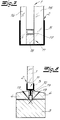
- the fire protection component shown in the figures is equipped with a toughened glass pane 1 which has a circumferential fillet edge 2.
- the lip 2 of the glass pane 1 has a heat-conducting support 5 on both surfaces.
- the lip 2 is inserted into a metal holding frame 3 with a glass holding strip 4 forming a groove for the lip 2.
- these are glass holding strips 4 independent components that are connected to the holding frame 3.
- a metallic thermal bridge profile strip 6 is also provided on both sides of the fillet edge 2, which, viewed in cross section, has a fillet edge flange 7, a cover section 8 and a radiation flange 9.
- the stand-up edge flange 7 is arranged between the support 5 of the stand-up edge 2 and the associated glass holding strip 4, abutting the stand-up edge 2.
- the cover section 8 covers the associated glass holding strip 4 and the radiation flange 9 lies on the outside in front of this glass holding strip 4. In this way it is achieved that the thermal bridge profile strip 6 absorbs heat energy in the event of a fire on the fire side and heat energy transferred on the opposite side via the filler rim 2 of the glass plate 1 releases to the environment.
- the support 5 comprises the edge 2 of the glass pane 1 in a U-shape.
- the pad 5 consists of a sheet metal profile, but it could also be applied galvanically or by vapor deposition.
- the pad 5 can also consist of a good heat-conducting enamel. It was not drawn that the edge 2 of the glass pane 1 can be pretreated by etching, so that microcracks are removed and the connection surface with the support 5 operates without the risk of cracking in the manner described.
- a thermal insulation material 10 is arranged between the thermal bridge profile strips 6 and the glass retaining strips 4.
- the thermal bridge profile strips 6 consist of a highly heat-conductive metal alloy, the melting point of which is below the melting point of the glass pane 1.
- the thermal bridge profile strips 6 and the support 5 of the front edge 2 are designed so that the thermal bridge profile strip 6 melts at least in certain areas on the fire side during the predetermined fire resistance period.
- a melting was indicated by dash-dotted lines in FIG. 1.
- the fire protection component has a fire resistance duration in fire tests according to DIN 4102 of over 60 minutes, preferably of over 90 minutes.
- the support 5 is formed by a heat-conducting component 5.
- the heat-conducting component 5 has a receiving groove 11 which receives the edge 2 of the glass pane 1.
- the two main sides of the glass pane are in thermal contact with the side legs of the receiving channel 11.
- Prestressed soda-lime glass is preferably used for the glass pane 1, preferably with a thickness of 10 mm, but glass pane thicknesses in the range from 6 mm to 15 mm can also be used.
- a particularly preferred material is strongly tempered soda lime glass.
- Conventional toughened soda-lime glass is toughened in areas between 70 MPa and 85 MPa, while heavily toughened glass is toughened in areas above 85 MPa, the upper limit being determined by those for Bias used equipment is limited.
- FIGS. 3 to 8 show, as further components of the glass pane structure, a holding frame 3 with setting blocks 12 and glass holding strips 4.
- the holding frame 3 is made of wood, and the glass holding strips 4 are fixed on the holding frame by means of countersunk steel screws 13 .
- the glass holding strips 4 can also be formed from the holding frame 3.
- the holding frame 3 can also be made of metal.
- the heat-conducting component 5 is separated from the glass retaining strips by thermal insulation material 10. It can be seen that the side legs of the receiving channel 11 have a length which corresponds to the thickness of the glass pane 1.
- the heat-conducting component 5 is made of metal in FIG. 3 and has a thickness sufficient for heat conduction, preferably 2 mm.
- the heat-conducting component 5 is made, for example, from aluminum or aluminum alloys or from stainless steel. It is preferably preformed. This preforming can be produced in any way, for example by cutting and bending. The heat-conducting component 5 can also be produced by extrusion. For a good thermal contact, an exact adaptation of the heat-conducting component 5 to the protrusion edge 2 of the glass pane 1 is necessary. At least the side legs of the receiving channel 11 should be in direct contact with the main sides of the glass pane 1. Basically, there is also the possibility of this contact through a highly heat-conductive, pasty or to improve adhesive substance between the receiving channel 11 and the glass pane 1.
- the side legs of the receiving channel 11 are preferably pre-bent inwards, so that the heat-conducting component 5 is widened by the fillet edge 2 of the glass pane 1 and, in so far, an intimate and firm contact is achieved.
- the heat-conducting component 5 can be arranged in sections on the circumference of the glass pane 1. This simplifies the assembly of the heat-conducting component 5.
- the base of the receiving groove 11 is in thermal contact with the glass sheet 1. This will usually be the case if the heat-conducting component 5 is placed on the edge 2 of the glass sheet 1 without adhesive as described above. It is important that the heat-conducting component 5 can sufficiently absorb the heat radiation from the fire.
- FIGS. 4 to 8 show advantageous configurations.
- the side legs of the receiving channel 11 protrude above the glass retaining strips 4 and thus absorb radiant heat of the fire particularly quickly in the event of a fire.
- the side legs preferably protrude at least 10 mm.
- the protruding side legs are visible. They can have a decorative coating.
- the protruding side legs of the receiving channel 11 of the heat-conducting component 5 are covered by a decorative cover 14.
- the decorative cover 14 can consist of extruded metal or plastic and is designed so that it does not significantly reduce the heat absorption of the heat-conducting component 5. For this reason, metallic decorative covers 14 should be in direct contact with the thermally conductive one Component 5 or the side legs stand.
- the decorative strips 14 are shaped such that they cover the glass retaining strips 4.
- composite glass panes for example laminated glass panes or multi-glazed glass panes, can also be used.
- 7 shows a glass pane 1 which is designed as a double-glazed glass pane unit.
- the individual panes 15 and 16 of the glass pane are separated from one another by a spacer 17, which can be made of a durable material, for example of steel.
- the sealing material 18 has a high temperature resistance and can be made of silicone, for example.
- the individual pane 15 has the required fire resistance and preferably consists of strongly prestressed soda-lime glass, the inset edge 2 having been freed from microcracks and crack formation points.
- the other single pane 16 can be made from conventional glass of reduced thickness. However, it goes without saying that both individual panes 15, 16 can also be fire-resistant in the manner described above.
- the double-glazed glass pane unit is used as a glass pane 1 in the expanded receiving groove 11 of the heat-conducting component 5. Double-glazed glass pane unit and heat-conducting component 5 can be connected in a holding frame 3 as shown in FIGS. 3 to 6.
- the fire protection component can be used by the glass panes 1, the thickness of which exceeds the width of the receiving groove formed by the glass retaining strips 4.
- the heat-conducting component 5 is provided with a web 19 which is held in the receiving groove, while the glass pane 1 is fixed between the side flanks of the receiving groove 11 outside the receiving groove.
- the web width is preferably selected so that it corresponds to the common glass pane thicknesses.
- decorative covers 14 can also be used in the exemplary embodiment shown in FIG. 8.
Landscapes
- Engineering & Computer Science (AREA)
- Civil Engineering (AREA)
- Structural Engineering (AREA)
- Joining Of Glass To Other Materials (AREA)
- Securing Of Glass Panes Or The Like (AREA)
- Special Wing (AREA)
Abstract
Description
- Die Erfindung betrifft ein Brandschutz-Bauelement mit einer Glasscheibe mit umlaufendem Einstandsrand, wobei der Einstandsrand auf beiden Oberflächen einer wärmeleitende Auflage aufweist.
- Bei dem bekannten Brandschutz-Bauelement des vorstehend beschriebenen Aufbaus (DE 30 44 718 A1) besitzt der Einstandsrand der Glasscheibe auf beiden Oberflächen eine Beschichtung als wärmeleitende Auflage. Die wärmeleitende Beschichtung ist unter Zwischenschaltung eines wärmedämmend wirkenden Isolierstoffes, zum Beispiel aus einem faserigen Füllmaterial, in die Aufnahmenut eingesetzt. Das hat sich bewährt, solange im Brandfall die thermische Beanspruchung nicht zu hoch ist und an die Feuerwiderstandsdauer zu hohe Anforderungen nicht gestellt werden. Eine Verbesserung der Feuerwiderstandsdauer ist bei der bekannten Ausführungsform erreichbar, indem man die Beschichtung über den freien Rand der Aufnahmenut und damit des wärmedämmenden Füllstoffes überstehen läßt. In Verbindung mit der Isolierung zwischen Einstandsrand und Rahmen ist die Wärmeleitung in den Einstandsrand durch die geringe Dicke der Beschichtung bei hoher thermischer Beanspruchung unzureichend.
- Der Erfindung liegt das technische Problem zugrunde, bei einem Brandschutz-Bauelement des eingangs beschriebenen Aufbaus die Feuerwiderstandsdauer beachtlich zu erhöhen, und zwar auch dann, wenn in einem Brandfall die thermischen Beanspruchungen extrem hoch sind.
- Zur Lösung dieses technischen Problems ist Gegenstand der Erfindung ein Brandschutz-Bauelement mit einer Glasscheibe mit umlaufendem Einstandsrand, wobei der Einstandsrand auf beiden Oberflächen eine wärmeleitende Auflage aufweist, und wobei die Auflage zur Ableitung hoher, im Brandfall aufgenommener Wärmeströme in den Einstandsrand ausgebildet ist.
- Eine erste, vom Patentanspruch 1 ausgehende Weiterbildung der Erfindung sieht vor, daß der mit der Auflage versehene Einstandsrand mit eine Aufnahmenut für den Einstandsrand bildenden Glashalteleisten an einen Halterahmen angeschlossen ist sowie beidseitig des Einstandsrandes eine metallische Wärmebrückenprofilleiste vorgesehen ist, die, im Querschnitt betrachtet, einen Einstandsrandflansch, einen Abdeckabschnitt und einen Strahlungsflansch aufweist, wobei im Brandfall die Wärmbrückenprofilleiste auf der Feuerseite Wärmeenergie aufnimmt und auf der gegenüberliegenden Seite über den Einstandsrand der Glasscheibe übertragene Wärmeenergie an die Umgebung abgibt.
- Bei einem solchen Brandschutz-Bauelement bestehen der Halterahmen und die Glashalteleisten regelmäßig aus einer geeigneten Stahllegierung oder einer geeigneten Metallegierung. Grundsätzlich besteht aber auch die Möglichkeit, den Halterahmen aus Holz zu fertigen. Die Glashalteleisten können an den Halterahmen angeformt oder als selbständige Bauteile aufgesetzt sein.
- Nach einer weiteren bevorzugten Ausführungsform ist der Einstandsrandflansch zwischen der Beschichtung des Einstandsrandes und der zugeordneten Glashalteleiste sowie an dem Einstandsrand anliegend angeordnet, deckt der Abdeckabschnitt glasscheibenseitig die zugeordnete Glashalteleiste ab und liegt der Strahlungsflansch außenseitig vor dieser Glashalteleiste.
- Vorzugsweise ist die Glasscheibe vorgespannt. Die vorgespannte Glasscheibe besteht zum Beispiel aus thermisch oder chemisch vorgespanntem Floatglas, aus vorgespanntem oder nicht vorgespanntem Glas niedriger Wärmedehnung, beispielsweise Borosilikatglas, oder anderen geeigneten Gläsern.
- Erfindungsgemäß wird durch den Wärmefluß, der über den Einstandsrand der Glasscheibe geführt wird, erreicht, daß für einen vorbestimmbaren Zeitraum bzw. einen vorgebbaren Temperaturbereich eines Brandfalles sichergestellt ist, daß der Temperaturgradient zwischen dem mittleren Bereich der Glasscheibe und dem Scheibenrand zunächst so gering gehalten wird, daß die kritische, durch den Brandfall eingeleitete Aufheizphase der Glasscheibe sicher überstanden wird. Im weiteren Verlauf des Brandfalles bleibt der beschriebene Temperaturgradient so groß, daß der Glasscheibenrand über lange Zeiträume unterhalb der Erweichungstemperatur bleibt. Das beruht darauf, daß erfindungsgemäß ein wärmeleitfähiger Werkstoff, nämlich ein Metall, als Wärmebrücke eingesetzt und so angeordnet ist, daß die Wärmebrücke in leitender Verbindung sowohl mit dem Einstandsrand der Glasscheibe als auch mit der Umgebung ist. Auf der Feuerseite ist die Wärmebrückenprofilleiste erheblicher Wärmestrahlung und Konvektion ausgesetzt. Auf der gegenüberliegenden Seite steht die Wärmebrückenprofilleiste mit der dort regelmäßig wesentlich kälteren Umgebung in Verbindung. In beiden Fällen erfolgt der Wärmeübergang durch Strahlung und Konvektion, jedoch muß der Wärmestrom den Einstandsrand der Glasscheibe passieren, der wegen der daraus resultierenden Abkühlung langzeitig stabil bleibt.
- Im einzelnen bestehen im Rahmen der Erfindung mehrere Möglichkeiten der weiteren Ausbildung und Gestaltung. Obgleich vorzugsweise der Einstandsrand der Glasscheibe lediglich auf beiden Oberflächen eine wärmeleitende Beschichtung aufweist, besteht auch die Möglichkeit die Anordnung so zu treffen, daß die Beschichtung den Einstandsrand U-förmig umfaßt. Die Beschichtung kann zum Beispiel aus Blechstreifen, aus einem Blechprofil, aus galvanisch oder durch Bedampfung aufgebrachten Metallstreifen oder einer gut wärmeleitenden Emaillierung bestehen. Durch den anliegenden Einstandsrandflansch kann trotz der vergleichsweise dünnen Beschichtung ein hoher Wärmestrom in den Einstandsrand eingeleitet werden. Wird mit Blechstreifen oder mit einem Blechprofil gearbeitet, so besitzt dieses Blech eine Dicke von unter einem Millimeter, beispielsweise im Bereich von 0,2 bis 0,6 mm. Im Rahmen der Erfindung liegt es, den Einstandsrand der Glasscheibe durch eine Ätzung mit einer Verbindungsoberfläche zu versehen. Die Ätzung entfernt Mikrorisse, die unter den Brandfallbeanspruchungen zu vorzeitigen Brüchen führen könnten. Im Rahmen der Erfindung liegt es fernerhin, zwischen den Wärmebrückenprofilleisten und den Glashalteleisten eine Wärmedämmstoff anzuordnen.
- Erfindungsgemäß läßt sich bei einem Halterahmen aus Metall durch die Auslegung der Wärmebrückenprofilleiste und der Beschichtung des Einstandsrandes erreichen, daß die Brandschutz-Bauelemente eine Feuerwiderstandsdauer bei einem Brandversuch nach DIN 4102 von über 60 Minuten, vorzugsweise von über 90 Minuten, aufweist.
- Im Sinne einer Optimierung lehrt die Erfindung in diesem Zusammenhang, daß die Wärmebrückenprofilleisten aus einer gut wärmeleitfähigen Metallegierung bestehen, deren Schmelzpunkt unter dem Schmelzpunkt der Glasscheibe liegt. Insoweit kann beispielsweise mit Aluminiumlegierungen, einer Zinnlegierung oder auch mit Kupferlegierungen gearbeitet werden. Man kann auf diese Weise durch eine Phasenumwandlung der Metallegierung einen zusätzlichen Kühleffekt erzielen. Ein vergleichbares Ergebnis ist auch erzielbar, wenn die Wärmebrückenprofilleisten zumindest auf den Abdeckabschnitten und Strahlungsflanschen einen Farbanstrich hoher IR-Absorption und IR-Emissivität aufweisen. Jedenfalls kann der oben erwähnte zusätzliche Kühleffekt dadurch erreicht werden, daß die Wärmebrückenprofilleisten und die Beschichtung so ausgelegt sind, daß die Wärmebrückenprofilleisten feuerseitig während der vorgegebenen Feuerstandsdauer zumindest bereichsweise schmelzen, so daß eine Phasenumwandlungskühlung stattfindet.
- Die erreichten Vorteile sind zusammengefaßt darin zu sehen, daß bei dem erfindungsgemäßen Brandschutz-Bauelement zunächst Wärmeenergie vom Brandherd in verhältnismäßig kurzer Zeit zu den Einstandsrändern der Glasscheibe geleitet wird, daß aber im weiteren Verlauf des Brandes, wenn die Temperatur des umlaufenden Einstandsrands und der daran angeschlossenen Bereiche der Glasscheibe sich schon der Erweichungstemperatur nähert, ein Kühleffekt durch Abstrahlung und Konvektion über die Wärmebrückenprofilleiste auf der gegenüberliegenden Seite der Glasscheibe erreicht wird, und zwar derart, daß eine ausreichende Feuerwiderstandsdauer sich einstellt. Diese kann dadurch optimiert werden, daß die schon beschriebene Phasenumwandlungskühlung verwirklicht wird. Im Ergebnis erreicht man bei Brandversuchen nach DIN 4102 ohne weiteres Feuerwiderstandsdauern von 60 Minuten und mehr und sogar von über 90 Minuten.
- Die vorstehend beschriebenen Ausführungsformen der Erfindung werden weiter unten anhand der Fig. 1 und 2 ausführlich erläutert.
- Eine zweite, vom Patentanspruch 1 ausgehende Weiterbildung der Erfindung sieht vor, daß die Auflage durch ein wärmeleitendes Bauteil mit einer Aufnahmerinne gebildet wird, welche Aufnahmerinne den Einstandsrand der Glasscheibe aufnimmt, wobei die Seitenschenkel der Aufnahmerinne mit den beiden Hauptseiten der Glasscheiben in thermischem Kontakt stehen. Hierbei leitet das wärmeleitende Bauteil im Brandfall über die Kontaktfläche zwischen den Seitenschenkeln der Aufnahmerinne und den Hauptseiten der Glasscheibe Wärme in den Einstandsrand der Glasscheibe ein. Durch die Verwendung des wärmeleitenden Bauteils ist die Dicke der Auflage gegenüber einer Beschichtung erhöht, so daß die Wärmeleitung in den Einstandsrand verbessert wird und auch bei hoher thermischer Beanspruchung kein Versagen der Glasscheibe aufgrund thermischer Spannungen auftritt.
- Vorzugsweise weist zumindest ein Seitenschenkel eine Länge auf, die betragsmäßig der Glasscheibendicke entspricht bzw. die Glasscheibendicke übertrifft. Es versteht sich, daß beide Seitenschenkel gleich lang ausgeführt sein können. Vorzugsweise besteht das wärmeleitende Bauteil aus Metall. Die Metalldicke sollte dabei beispielsweise > 0,5 mm, vorzugsweise > 1 mm und besonders bevorzugt etwa 2 mm betragen. Das wärmeleitende Bauteil muß nicht am gesamten Umfang der Glasscheibe angeordnet sein. Da eine Rißbildung im Brandfall regelmäßig im Zentrum der längeren Seite der Glasscheibe auftritt, ist es möglich, aus Einsparungsgründen die Ecken der Glasscheibe nicht mit dem wärmeleitenden Bauteil zu versehen. Bei einer Scheibe mit einem ausreichend großen Verhältnis der Seitenlängen, beispielsweise 2 : 1, besteht die Möglichkeit, das wärmeleitende Bauteil nur auf den längeren Seiten einzusetzen. Vorzugsweise ist das wärmeleitende Bauteil an zumindest zwei Dritteln des Umfanges der Glasscheibe angeordnet. Dabei ist es vorteilhaft, zumindest 80 %, vorzugsweise zumindest 90 % des Umfanges der Glasscheibe mit dem wärmeleitenden Bauteil zu versehen. Es versteht sich, daß bei einer vollständigen Umhüllung der Glasscheibe durch das wärmeleitende Bauteil eine fehlerhafte Verteilung des wärmeleitenden Bauteiles auf dem Umfang sicher vermieden wird. Es versteht sich weiter, daß das wärmeleitende Bauteil nicht zusammenhängend, sondern auch abschnittsweise am Umfang der Glasscheibe angeordnet sein kann. Vorzugsweise besteht das wärmeleitende Bauteil aus extrudiertem Metall. Hinsichtlich der Montage ist es von Vorteil, wenn das wärmeleitende Bauteil vorgeformt ist. Die Aufnahmerinne des wärmeleitenden Bauteiles kann außer den Seitenschenkeln auch eine Basis aufweisen, die im thermischen Kontakt mit der Glasscheibe steht. Die Aufnahmerinne kann dabei einen U-förmigen Querschnitt aufweisen. Die Feuerbeständigkeit von Glas nimmt regelmäßig mit der Dicke des Glases zu. Erfindungsgemäß wird vorzugsweise gehärtetes Glas mit einer Dicke von zumindest 10 mm eingesetzt. Dabei besteht die Möglichkeit, das wärmeleitende Bauteil mit einem Steg zu versehen und diesen Steg in die Aufnahmenut einzusetzen, wobei die Glasscheibe außerhalb der Aufnahmenut durch die Seitenschenkel der Aufnahmerinne des wärmeleitenden Bauteils festgehalten wird.
- Vorzugsweise besteht die Glasscheibe aus vorgespanntem, insbesondere stark vorgespanntem Glas. Erfindungsgemäß kann die Glasscheibe auch als mehrfachverglaste Glasscheibeneinheit, vorzugsweise als doppelverglaste Glasscheibeneinheit, ausgebildet sein. Es versteht sich, daß auch verstärkte Gläser und Verbundglas eingesetzt werden können.
- Vorzugsweise wird das wärmeleitende Bauteil so in die Aufnahmenut eingesetzt, daß die Seitenschenkel der Aufnahmerinne bündig mit den Glashalteleisten abschließen. Da jedoch die Wärmeaufnahme des wärmeleitenden Bauteils durch ein Hervorkragen der Seitenschenkel über die Glashalteleisten hinaus verbessert wird, sieht eine bevorzugte Ausführungsform der Erfindung vor, daß zumindest ein Seitenschenkel der Aufnahmerinne über die Glashalteleiste hervorkragt. Vorzugsweise ragt dieser Seitenschenkel zumindest 10 mm hervor. Eine weitere bevorzugte Ausführungsform sieht vor, diesen Seitenschenkel mit einer Dekorabdeckung abzudecken. Vorzugsweise ist diese Abdeckung aus Kunststoff gefertigt, der im Brandfall schmilzt und hierbei das wärmeleitende Bauteil der Wärmestrahlung des Brandes zugänglich macht. Es besteht jedoch auch die Möglichkeit, die Dekorabdeckung aus wärmeleitendem Material, beispielsweise aus Metall herzustellen. Es versteht sich, daß die Dekorabdeckung gefärbt sein kann.
- Vorzugsweise wird das wärmeleitende Bauteil vor dem Transport auf dem Umfang der Glasscheibe festgesetzt. Dies hat den Vorteil, daß das wärmeleitende Bauteil den überdeckten Einstandsbereich der Glasscheibe während der Handhabung, des Transportes und der Verglasung schützt. Hierdurch werden mechanische Schäden vermieden, die insbesondere die Feuerbeständigkeit der Glasscheibe reduzieren würden. Dies gilt insbesondere, wenn vorgespanntes bzw. gehärtetes Glas verwendet wird, bei dem ein Sprung unmittelbar oder zu einem späteren Zeitpunkt ohne Vorwarnung zum Zerspringen der Scheibe führen kann. In diesem Zusammenhang ist es vorteilhaft, wenn der Einstandsrand der Glasscheibe von Mikrorissen und Rißbildungspunkten befreit ist. Dabei ist es von Vorteil, die Glasscheibe` vorzuspannen, nachdem sie von Mikrorissen und Rißbildungspunkten befreit ist, und daran anschließend den Einstandrand in das wärmeleitende Bauteil einzusetzen.
- Im folgenden wird die Erfindung anhand einer lediglich ein Ausführungsbeispiel darstellenden Zeichnung ausführlicher erläutert. Es zeigen in schematischer Darstellung
- Fig. 1 und 2
- einen Vertikalschnitt durch ein erfindungsgemäßes Brandschutz-Bauelement in der in Abschnitt I erläuterten Ausführungsform mit Wärmebrückenprofilleiste und
- Fig. 3 bis 8
- Vertikalschnitte durch Brandschutz-Bauelemente in der in Abschnitt II erläuterten Ausführungsform mit wärmeleitendem Bauteil.
- Das in den Figuren dargestellte Brandschutz-Bauelement ist mit einer vorgespannten Glasscheibe 1 ausgerüstet, die einen umlaufenden Einstandsrand 2 aufweist. Der Einstandsrand 2 der Glasscheibe 1 besitzt auf beiden Oberflächen eine wärmeleitende Auflage 5. In den Fig. 1 und 2 ist der Einstandsrand 2 in einen metallischen Halterahmen 3 mit eine Aufnahmenut für den Einstandsrand 2 bildenden Glashalteleisten 4 eingesetzt. Im Ausführungsbeispiel sind diese Glashalteleisten 4 selbständige Bauteile, die mit den Halterahmen 3 verbunden sind. Beidseitig des Einstandsrandes 2 ist fernerhin eine metallische Wärmebrückenprofilleiste 6 vorgesehen, die, im Querschnitt betrachtet, einen Einstandsrandflansch 7, einen Abdeckabschnitt 8 und einen Strahlungsflansch 9 aufweist. Der Einstandsrandflansch 7 ist zwischen der Auflage 5 des Einstandsrandes 2 und der zugeordneten Glashalteleiste 4, an dem Einstandsrand 2 anliegend, angeordnet. Der Abdeckabschnitt 8 bedeckt die zugeordnete Glashalteleiste 4 und der Strahlungsflansch 9 liegt außenseitig vor dieser Glashalteleiste 4. Auf diese Weise wird erreicht, daß die Wärmebrückenprofilleiste 6 im Brandfall auf der Feuerseite Wärmeenergie aufnimmt und an der gegenüberliegenden Seite über den Einstandsrand 2 der Glasscheibe 1 übertragene Wärmeenergie an die Umgebung abgibt.
- Im Ausführungsbeispiel gemäß Fig. 1 und Fig. 2 umfaßt die Auflage 5 den Einstandsrand 2 der Glasscheibe 1 U-förmig. Die Auflage 5 besteht aus einem Blechprofil, sie könnte aber auch galvanisch oder durch Bedampfung aufgebracht sein. Die Auflage 5 kann auch aus einer gut wärmeleitenden Emaillierung bestehen. Nicht gezeichnet wurde, daß der Einstandsrand 2 der Glasscheibe 1 durch eine Ätzung vorbehandelt sein kann, so daß Mikrorisse abgetragen sind und die Verbindungsoberfläche mit der Auflage 5 ohne Rißgefährdung in der beschriebenen Art und Weise arbeitet. Zwischen den Wärmebrückenprofilleisten 6 und den Glashalteleisten 4 ist ein Wärmedämmstoff 10 angeordnet.
- Im Ausführungsbeispiel und nach bevorzugter Ausführungsform der Erfindung bestehen die Wärmebrückenprofilleisten 6 aus einer gut wärmeleitfähigen Metallegierung, deren Schmelzpunkt unter dem Schmelzpunkt der Glasscheibe 1 liegt. Es kann sich zum Beispiel um eine geeignete Aluminiumlegierung handeln. Auf diese Weise kann eine zusätzliche Phasenumwandlungskühlung erreicht werden, und zwar dadurch, daß die Wärmebrückenprofilleisten 6 und die Auflage 5 des Einstandsrandes 2 so ausgelegt sind, daß die Wärmebrückenprofilleiste 6 feuerseitig während der vorgegebenen Feuerwiderstandsdauer zumindest bereichsweise schmilzt. Ein solches Abschmelzen wurde in der Fig. 1 strichpunktiert angedeutet. Im Ergebnis erreicht man, daß das Brandschutz-Bauelement eine Feuerwiderstandsdauer bei Brandversuchen nach DIN 4102 von über 60 Minuten, vorzugsweise von über 90 Minuten aufweist.
- In den Fig. 3 bis 8 wird die Auflage 5 durch ein wärmeleitendes Bauteil 5 gebildet. Das wärmeleitende Bauteil 5 besitzt eine Aufnahmerinne 11, welche den Einstandsrand 2 der Glasscheibe 1 aufnimmt. Die beiden Hauptseiten der Glasscheibe sind mit den Seitenschenkeln der Aufnahmerinne 11 in thermischem Kontakt. Für die Glasscheibe 1 wird vorzugsweise vorgespanntes Natronkalkglas verwendet, vorzugsweise mit einer Dicke von 10 mm, aber es können auch Glasscheibendicken im Bereich von 6 mm bis 15 mm eingesetzt werden. Ein besonders bevorzugtes Material ist stark vorgespanntes Natronkalkglas. Herkömmliches vorgespanntes Natronkalkglas wird in Bereichen zwischen 70 MPa und 85 MPa vorgespannt, während stark vorgespanntes Glas in Bereichen über 85 MPa vorgespannt wird, wobei die Obergrenze durch die für die Vorspannung verwendete Ausrüstung begrenzt wird. Fig. 3 zeigt als weitere Bauteile des Glasscheiben-Bauwerkes einen Halterahmen 3 mit Setzblöcken 12 und Glashalteleisten 4. In den Fig. 3 bis 8 ist der Halterahmen 3 aus Holz, und die Glashalteleisten 4 werden mit Hilfe von versenkbaren Stahlschrauben 13 auf dem Halterahmen festgesetzt. Es versteht sich, daß die Glashalteleisten 4 aber auch aus dem Halterahmen 3 ausgeformt sein können. Es versteht sich weiterhin, daß der Halterahmen 3 auch aus Metall gefertigt sein kann. In den Fig. 3 bis 8 ist das wärmeleitende Bauteil 5 durch Wärmedämmstoff 10 von den Glashalteleisten getrennt. Man erkennt, daß die Seitenschenkel der Aufnahmerinne 11 eine Länge aufweisen, die der Dicke der Glasscheibe 1 entspricht. Das wärmeleitende Bauteil 5 ist in Fig. 3 aus Metall gefertigt und besitzt eine zur Wärmeleitung ausreichende Dicke, vorzugsweise 2 mm. Bei größeren Metalldicken rechtfertigt die verbesserte Wärmeleitfähigkeit im allgemeinen nicht mehr die erhöhten Materialkosten. Das wärmeleitende Bauteil 5 ist beispielsweise aus Aluminium oder Aluminiumlegierungen oder aus rostfreiem Stahl hergestellt. Es ist vorzugsweise vorgeformt. Diese Vorformung kann auf beliebige Weise, beispielsweise` durch Schneiden und Biegen erzeugt werden. Das wärmeleitende Bauteil 5 kann aber auch durch Extrusion erzeugt werden. Für einen guten thermischen Kontakt ist eine genaue Anpassung des wärmeleitenden Bauteils 5 an den Einstandsrand 2 der Glasscheibe 1 erforderlich. Zumindest die Seitenschenkel der Aufnahmerinne 11 sollten im direkten Kontakt mit den Hauptseiten der Glasscheibe 1 stehen. Grundsätzlich besteht auch die Möglichkeit, diesen Kontakt durch eine hoch wärmeleitende, pastenförmige oder klebende Substanz zwischen der Aufnahmerinne 11 und der Glasscheibe 1 zu verbessern. Vorzugsweise sind die Seitenschenkel der Aufnahmerinne 11 nach innen vorgebogen, so daß das wärmeleitende Bauteil 5 durch den Einstandsrand 2 der Glasscheibe 1 aufgeweitet und insofern ein inniger und fester Kontakt erreicht wird. Das wärmeleitende Bauteil 5 kann abschnittsweise auf dem Umfang der Glasscheibe 1 angeordnet sein. Hierdurch wird die Montage des wärmeleitenden Bauteils 5 vereinfacht. In Fig. 3 steht auch die Basis der Aufnahmerinne 11 in thermischen Kontakt mit der Glasscheibe 1. Dies wird in der Regel dann der Fall sein, wenn das wärmeleitende Bauteil 5 wie oben beschrieben ohne Klebstoff auf den Einstandsrand 2 der Glasscheibe 1 aufgesetzt wird. Es ist von Bedeutung, daß das wärmeleitende Bauteil 5 in ausreichendem Maße die Wärmestrahlung des Brandes absorbieren kann. Hierzu zeigen die Figuren 4 bis 8 vorteilhafte Ausgestaltungen. In Fig. 4 kragen die Seitenschenkel der Aufnahmerinne 11 über die Glashalteleisten 4 hervor und nehmen so im Brandfall besonders schnell Strahlungswärme des Brandes auf. Vorzugsweise kragen die Seitenschenkel dabei zumindest 10 mm hervor. In Fig. 4 sind die hervorgekragenden Seitenschenkel sichtbar. Sie können hierbei eine dekorative Beschichtung aufweisen. In Fig. 5 werden die hervorkragenden Seitenschenkel der Aufnahmerinne 11 des wärmeleitenden Bauteils 5 von einer Dekorabdeckung 14 abgedeckt. Die Dekorabdeckung 14 kann aus extrudiertem Metall oder Kunststoff bestehen und ist so ausgeführt, daß sie die Wärmeaufnahme des wärmeleitenden Bauteiles 5 nicht wesentlich reduziert. Aus diesem Grunde sollten metallische Dekorabdeckungen 14 unmittelbar im Kontakt mit dem wärmeleitenden Bauteil 5 bzw. den Seitenschenkeln stehen. Bei der Verwendung von Kunststoff sollte ein nichtbrennbarer Kunststoff verwendet werden, der im Brandfall schmilzt. In Fig. 6 sind die Dekorleisten 14 so ausgeformt, daß sie die Glashalteleisten 4 überdecken. Anstelle der in den Fig. 3 bis 6 gezeigten einfachen Glasscheibe 1 können auch zusammengesetzte Glasscheiben, beispielsweise Verbundglasscheiben oder mehrfachverglaste Glasscheiben verwendet werden. Fig. 7 zeigt eine Glasscheibe 1, die als doppelverglaste Glasscheibeneinheit ausgebildet ist. Die Einzelscheiben 15 und 16 der Glasscheibe werden durch einen Abstandshalter 17 voneinander getrennt, wobei dieser aus beständigem Material, beispielsweise aus Stahl, gefertigt sein kann. Das Dichtungsmaterial 18 weist eine hohe Temperaturbeständigkeit auf und kann beispielsweise aus Silikon bestehen. In Fig. 7 weist zumindest die Einzelscheibe 15 die benötigte Feuerbeständigkeit auf und besteht vorzugsweise aus stark vorgespanntem Natronkalkglas, wobei der Einstandsrand 2 von Mikrorissen und Rißbildungspunkten befreit wurde. Die andere Einzelscheibe 16 kann aus herkömmlichem Glas geringerer Dicke gefertigt sein. Es versteht sich jedoch, daß auch beide Einzelscheiben 15, 16 auf die oben beschriebene Weise feuerbeständig ausgeführt sein können. In jedem Fall wird die doppeltverglaste Glasscheibeneinheit als Glasscheibe 1 in die erweiterte Aufnahmerinne 11 des wärmeleitenden Bauteils 5 eingesetzt. Doppeltverglaste Glasscheibeneinheit und wärmeleitendes Bauteil 5 können wie in den Fig. 3 bis 6 gezeigt in einen Halterahmen 3 angeschlossen werden. Fig. 8 zeigt eine Ausführungsform des erfindungsgemäßen Brandschutz-Bauelementes, durch die Glasscheiben 1 verwendet werden können, deren Dicke die Breite der durch die Glashalteleisten 4 gebildeten Aufnahmenut übertrifft. In diesem Fall ist das wärmeleitende Bauteil 5 mit einem Steg 19 versehen, der in der Aufnahmenut gehalten ist, während die Glasscheibe 1 zwischen den Seitenflanken der Aufnahmerinne 11 außerhalb der Aufnahmenut fixiert wird. Vorzugsweise ist die Stegbreite so gewählt, daß sie den gängigen Glasscheibendicken entspricht. Es versteht sich, daß auch bei dem in Fig. 8 gezeigten Ausführungsbeispiel Dekorabdeckungen 14 verwendet werden können.
Claims (28)
- Brandschutz-Bauelement mit einer Glasscheibe (1) mit umlaufendem Einstandsrand (2), wobei der Einstandsrand (2) auf beiden Oberflächen eine wärmeleitende Auflage (5) aufweist, und wobei die Auflage zur Ableitung hoher, im Brandfall aufgenommener Wärmeströme in den Einstandsrand ausgebildet ist.
- Brandschutz-Bauelement nach Anspruch 1, wobei der mit der Auflage (5) versehene Einstandsrand mit eine Aufnahmenut für den Einstandsrand (2) bildenden Glashalteleisten (4), an einen Halterahmen (3) angeschlossen ist, sowie beidseitig des Einstandsrandes (2) eine metallische Wärmebrückenprofilleiste (6) vorgesehen ist, die, im Querschnitt betrachtet, einen Einstandsrandflansch (7), einen Abdeckabschnitt (8) und einen Strahlungsflansch (9) aufweist, wobei im Brandfall die Wärmebrückenprofilleiste (6) auf der Feuerseite Wärmeenergie aufnimmt und auf der gegenüberliegenden Seite über den Einstandsrand (2) der Glasscheibe (1) übertragene Wärmeenergie an die Umgebung abgibt.
- Brandschutz-Bauelement nach Anspruch 2, wobei der Einstandsrandflansch (7) zwischen der Auflage (5) des Einstandsrandes (2) und der zugeordneten Glashalteleiste (4) sowie an dem Einstandsrand (2) anliegend angeordnet ist, der Abdeckabschnitt (8) die zugeordnete Glashalteleiste (4) abdeckt und der Strahlungsflansch (9) außenseitig vor dieser Glashalteleiste (4) liegt.
- Brandschutz-Bauelement nach einem der Ansprüche 1 bis 3, wobei die Auflage (5) den Einstandsrand (2) U-förmig umfaßt.
- Brandschutz-Bauelement nach einem der Ansprüche 1 bis 4, wobei die Auflage (5) aus Blechstreifen, aus einem Blechprofil, aus galvanisch oder durch Bedampfung aufgebrachtem Metallstreifen oder einer gut wärmeleitenden Emaillierung besteht.
- Brandschutz-Bauelement nach einem der Ansprüche 1 bis 5, wobei der Einstandsrand (2) der Glasscheibe (1) eine durch Ätzung erzeugte Verbindungsoberfläche aufweist.
- Brandschutz-Bauelement nach einem der Ansprüche 2 bis 6, wobei zwischen den Wärmebrückenprofilleisten (6) und den Glashalteleisten (4) ein Wärmedämmstoff (10) angeordnet ist.
- Brandschutz-Bauelement nach einem der Ansprüche 2 bis 7, wobei der Halterahmen aus Metall besteht und die Wärmebrückenprofilleisten (6) und die Auflage (5) des Einstandsrandes (2) so ausgelegt sind, daß das Brandschutz-Bauelement eine Feuerwiderstandsdauer bei einem Brandversuch nach DIN 4102 von über 60 Minuten, vorzugsweise von über 90 Minuten, aufweist.
- Brandschutz-Bauelement nach einem der Ansprüche 2 bis 8, wobei die Wärmebrückenprofilleisten (6) aus einer gut wärmeleitetenden Metallegierung bestehen, deren Schmelzpunkt unter dem Schmelzpunkt der Glasscheibe liegt.
- Brandschutz-Bauelement nach einem der Ansprüche 2 bis 9, wobei die Wärmebrückenprofilleisten (6) zumindest auf den Abdeckabschnitten (8) und Strahlungsflanschen (9) einen Farbanstrich hoher IR-Absorption und IR-Emissivität aufweisen.
- Brandschutz-Bauelement nach einem der Ansprüche 2 bis 10, wobei die Wärmebrückenprofilleisten (6) und die Auflage (5) des Einstandsrandes (2) so ausgelegt sind, daß die Wärmebrückenprofilleiste (6) feuerseitig während der vorgegebenen Feuerstandsdauer zumindest bereichsweise schmilzt.
- Brandschutz-Bauelement nach einem der Ansprüche 1 bis 11, wobei die Auflage (5) durch ein wärmeleitendes Bauteil (5) mit einer Aufnahmerinne (11) gebildet wird, welche Aufnahmerinne (11) den Einstandsrand (2) der Glasscheibe (1) aufnimmt, wobei die Seitenschenkel der Aufnahmerinne (11) mit den beiden Hauptseiten der Glasscheibe (1) in thermischem Kontakt stehen.
- Brandschutz-Bauelement nach Anspruch 12, wobei die Aufnahmerinne (11) zumindest einen Seitenschenkel aufweist, dessen Länge der Glasscheibendicke entspricht bzw. die Glasscheibendicke übertrifft.
- Brandschutz-Bauelement nach Anspruch 12 oder 13, wobei das wärmeleitende Bauteil (5) aus Metall mit einer Dicke > 0,5 mm, vorzugsweise > 1 mm, gefertigt ist.
- Brandschutz-Bauelement nach Anspruch 14, wobei das Metall ungefähr 2 mm dick ist.
- Brandschutz-Bauelement nach einem der Ansprüche 12 bis 15, wobei das wärmeleitende Bauteil (5) an zumindest zwei Dritteln des Umfanges der Glasscheibe (1) angeordnet ist.
- Brandschutz-Bauelement nach einem der Ansprüche 12 bis 16, wobei das wärmeleitende Bauteil (5) aus extrudiertem Metall besteht.
- Brandschutz-Bauelement nach einem der Ansprüche 12 bis 17, wobei das wärmeleitende Bauteil (5) vorgeformt ist.
- Brandschutz-Bauelement nach einem der Ansprüche 12 bis 18, wobei die Basis der Aufnahmerinne (11) im thermischen Kontakt mit der Glasscheibe steht.
- Brandschutz-Bauelement nach einem der Ansprüche 12 bis 19, wobei die Aufnahmerinne (11) einen U-förmigen Querschnitt hat.
- Brandschutz-Bauelement nach einem der Ansprüche 12 bis 20, wobei die Glasscheibe 1 zumindest 10 mm dick ist und das wärmeleitende Bauteil (5) mit einem Steg (19) versehen ist, der zur Verglasung in die Aufnahmenut einsetzbar ist, wobei die Glasscheibe (1) außerhalb der Aufnahmenut durch die Seitenschenkel der Aufnahmerinne (11) des wärmeleitenden Bauteils (5) festgehalten wird.
- Brandschutz-Bauelement nach einem der Ansprüche 1 bis 21, wobei die Glasscheibe (1) aus vorgespanntem, vorzugsweise stark vorgespanntem Glas besteht.
- Brandschutz-Bauelement nach einem der Ansprüche 1 bis 22, wobei die Glasscheibe (1) als mehrfach verglaste Glasscheiben-Einheit (1) ausgebildet ist.
- Brandschutz-Bauelement nach einem der Ansprüche 12 bis 23, wobei zumindest ein Seitenschenkel der Aufnahmerinne (11) über die Glashalteleisten (4) hervorkragt.
- Brandschutz-Bauelement nach Anspruch 24, wobei der Seitenschenkel zumindest 10 mm hervorkragt.
- Brandschutz-Bauelement nach Anspruch 24 oder 25, wobei der hervorkragende Seitenschenkel mit einer Dekorabdeckung (14) abgedeckt ist.
- Brandschutz-Bauelement nach einem der Ansprüche 12 bis 26, wobei die Glasscheibe (1) beim Transport in das wärmeleitende Bauteil (5) eingesetzt ist.
- Brandschutz-Bauelement nach Anspruch 27, wobei die Glasscheibe (1) einen von Mikrorissen und Rißbildungspunkten befreiten Einstandsrand (2) besitzt und im vorgespannten, vorzugsweise stark vorgespanntem Zustand eingesetzt wird.
Applications Claiming Priority (4)
| Application Number | Priority Date | Filing Date | Title |
|---|---|---|---|
| DE19934339331 DE4339331A1 (de) | 1993-11-19 | 1993-11-19 | Brandschutz-Bauelement mit einer Glasscheibe |
| DE4339331 | 1993-11-19 | ||
| GB939323831A GB9323831D0 (en) | 1993-11-19 | 1993-11-19 | Fire-resistant glazing |
| GB9323831 | 1993-11-19 |
Publications (2)
| Publication Number | Publication Date |
|---|---|
| EP0654578A1 true EP0654578A1 (de) | 1995-05-24 |
| EP0654578B1 EP0654578B1 (de) | 1998-04-22 |
Family
ID=25931316
Family Applications (1)
| Application Number | Title | Priority Date | Filing Date |
|---|---|---|---|
| EP94117223A Expired - Lifetime EP0654578B1 (de) | 1993-11-19 | 1994-11-01 | Brandschutz-Bauelement mit einer Glasscheibe |
Country Status (3)
| Country | Link |
|---|---|
| US (1) | US5628155A (de) |
| EP (1) | EP0654578B1 (de) |
| DE (1) | DE59405781D1 (de) |
Cited By (2)
| Publication number | Priority date | Publication date | Assignee | Title |
|---|---|---|---|---|
| GB2302902A (en) * | 1995-06-29 | 1997-02-05 | Hansen Fenlock Ltd | Fire resistant glazing assembly |
| AT12767U1 (de) * | 2011-06-21 | 2012-11-15 | Peneder Immobilien Gmbh | Brandschutz-pendeltür |
Families Citing this family (14)
| Publication number | Priority date | Publication date | Assignee | Title |
|---|---|---|---|---|
| GB2306541B (en) * | 1995-11-01 | 1998-12-30 | Jrm Doors Limited | Internal doors |
| GB2340166B (en) * | 1998-08-05 | 2003-01-15 | Dixon Internat Group Ltd | Glazing seal |
| ATE268859T1 (de) * | 2000-11-23 | 2004-06-15 | Schoerghuber Spezialtueren | T90-holzrahmen-glastür |
| US20050210830A1 (en) * | 2004-03-24 | 2005-09-29 | Lee Anthony B | Channel type frame adapter |
| DE102006050113A1 (de) * | 2006-10-25 | 2008-04-30 | Schott Ag | Brandschutzverglasung |
| US20080245003A1 (en) * | 2007-02-06 | 2008-10-09 | Kon Richard Henry | Hurricane door lite assembly, door, and related methods |
| US8683775B1 (en) * | 2012-09-07 | 2014-04-01 | Guardian Industries Corp. | Spacer system for installing vacuum insulated glass (VIG) window unit in window frame designed to accommodate thicker IG window unit |
| JP6076821B2 (ja) * | 2013-04-26 | 2017-02-08 | 三和シヤッター工業株式会社 | 板ガラスの取付構造 |
| GB201409871D0 (en) * | 2014-06-03 | 2014-07-16 | Pilkington Group Ltd | Fire resistant glazing screen |
| JP2016176244A (ja) * | 2015-03-20 | 2016-10-06 | Ykk Ap株式会社 | 防火建具 |
| EP3315337B1 (de) * | 2016-11-01 | 2021-06-02 | AGC Automotive Americas R & D, Inc. | Gekapselte glasrahmenanordnungen und zugehörige verfahren zur herstellung derselben |
| EP3315338B1 (de) | 2016-11-01 | 2023-06-28 | AGC Automotive Americas R & D, Inc. | Gekapselte glasrahmenanordnungen und zugehörige verfahren zur herstellung derselben |
| US10119323B2 (en) | 2016-11-01 | 2018-11-06 | Agc Automotive Americas R&D, Inc. | Encapsulated glass frame assemblies and associated methods for forming same |
| CA2988888C (en) * | 2016-12-16 | 2019-10-15 | Pella Corporation | Reserve cladding biasing |
Citations (2)
| Publication number | Priority date | Publication date | Assignee | Title |
|---|---|---|---|---|
| DE3044718A1 (de) | 1979-11-27 | 1981-09-10 | Bfg Glassgroup, Paris | Lichtdurchlaessige glasscheibe |
| EP0079257A1 (de) * | 1981-10-14 | 1983-05-18 | Saint Gobain Vitrage International | Fenster mit erhöhter Feuerwiderstandsfähigkeit und Verglasung dieses Fensters |
Family Cites Families (11)
| Publication number | Priority date | Publication date | Assignee | Title |
|---|---|---|---|---|
| CA751697A (en) * | 1967-01-31 | Dominion Steel And Coal Corporation | Frame construction | |
| US2781561A (en) * | 1953-02-26 | 1957-02-19 | Dicks Pontius Company | Glazing construction |
| US2808355A (en) * | 1956-06-11 | 1957-10-01 | North American Aviation Inc | Glass enclosure |
| US2976969A (en) * | 1958-05-05 | 1961-03-28 | Engineering Metal Products Cor | Curtain wall mullion |
| US3201831A (en) * | 1961-03-13 | 1965-08-24 | Moynahan Bronze Company | Window glazing construction |
| US3728833A (en) * | 1971-03-11 | 1973-04-24 | A Grossman | Frame construction having arcuate corners and a continuous feature strip |
| US4257202A (en) * | 1976-03-10 | 1981-03-24 | Armcor Industries, Inc. | Aluminum frame window with improved thermal insulation and method of making same |
| FR2355986A1 (fr) * | 1976-06-24 | 1978-01-20 | Saint Gobain | Perfectionnement au montage des vantaux vitres |
| US5042212A (en) * | 1988-09-12 | 1991-08-27 | Selig Golen | Security closure assembly |
| US4852312A (en) * | 1988-12-23 | 1989-08-01 | Plastmo Ltd. | Window frame assembly |
| DE3939149C1 (de) * | 1989-11-27 | 1991-01-03 | Schott Glaswerke, 6500 Mainz, De |
-
1994
- 1994-11-01 EP EP94117223A patent/EP0654578B1/de not_active Expired - Lifetime
- 1994-11-01 DE DE59405781T patent/DE59405781D1/de not_active Expired - Lifetime
- 1994-11-17 US US08/340,838 patent/US5628155A/en not_active Expired - Fee Related
Patent Citations (2)
| Publication number | Priority date | Publication date | Assignee | Title |
|---|---|---|---|---|
| DE3044718A1 (de) | 1979-11-27 | 1981-09-10 | Bfg Glassgroup, Paris | Lichtdurchlaessige glasscheibe |
| EP0079257A1 (de) * | 1981-10-14 | 1983-05-18 | Saint Gobain Vitrage International | Fenster mit erhöhter Feuerwiderstandsfähigkeit und Verglasung dieses Fensters |
Cited By (4)
| Publication number | Priority date | Publication date | Assignee | Title |
|---|---|---|---|---|
| GB2302902A (en) * | 1995-06-29 | 1997-02-05 | Hansen Fenlock Ltd | Fire resistant glazing assembly |
| GB2302902B (en) * | 1995-06-29 | 1998-12-23 | Hansen Fenlock Ltd | Fire resistant glazing |
| AT12767U1 (de) * | 2011-06-21 | 2012-11-15 | Peneder Immobilien Gmbh | Brandschutz-pendeltür |
| EP2538014A2 (de) | 2011-06-21 | 2012-12-26 | Peneder Immobilien GmbH | Brandschutz-Pendeltür |
Also Published As
| Publication number | Publication date |
|---|---|
| DE59405781D1 (de) | 1998-05-28 |
| US5628155A (en) | 1997-05-13 |
| EP0654578B1 (de) | 1998-04-22 |
Similar Documents
| Publication | Publication Date | Title |
|---|---|---|
| EP0654578B1 (de) | Brandschutz-Bauelement mit einer Glasscheibe | |
| DE69429699T2 (de) | Isolierverglasung und Vakuumerzeugungsverfahren dafür | |
| DE69619737T2 (de) | Feuerwiderstandsfähige Verglasung | |
| EP0638526B1 (de) | Brandschutzsicherheitsglas | |
| DE69328923T2 (de) | Verbesserungen für thermisch isolierende glasscheiben | |
| DE3231975C2 (de) | Feuerhemmender Verglasungsbauteil und Verfahren zu seiner Herstellung | |
| DE2501096B2 (de) | Randleiste zur herstellung von isolierglasscheiben, mehrscheiben-isolierglas sowie verfahren zu seiner herstellung | |
| EP1055046A1 (de) | Abstandhalterprofil für isolierscheibeneinheit | |
| WO1996001792A1 (de) | Verfahren zum herstellen von ebenen oder gewölbten glasplatten | |
| DE2247630B2 (de) | Verfahren zum Herstellen von Anzeigetafeln mit Gase ntladungsstrecken | |
| DE2414576A1 (de) | Feuerabschirmende glasscheibe und verfahren zu deren herstellung | |
| DE2439034C3 (de) | Gegen hitzeeinwirkung widerstandsfaehige verglasung | |
| EP0611854B1 (de) | Glasverbundplatte für Wand- und Gebäudeverkleidungen | |
| DE2951362A1 (de) | Plattenfoermiger sonnenkollektor | |
| EP0301166B1 (de) | Fassadenelement aus Glas | |
| DE3140785A1 (de) | "fenster mit erhoehter feuerwiderstandsfaehigkeit und silikatglasscheibe fuer dieses fenster" | |
| DE29602315U1 (de) | Glasverbundplatte für feststehende und/oder bewegbare Scheiben im Hochbau | |
| WO2009146818A1 (de) | Verfahren zur herstellung eines vakuumdichten verbundes zwischen einer glasscheibe und einem metallrahmen sowie glassscheibenverbund | |
| EP0325098A1 (de) | Verglasung mit einer Verbundscheibe und Verfahren zum Herstellen einer solchen Verbundscheibe | |
| DE1496467A1 (de) | Verfahren zur Herstellung einer Abdichtung als vorgeformte Teile verbindender Koerper oder als auf wenigstens einem Teil der Oberflaeche eines vorgeformten Koerpers haftend gebundene Materialschicht | |
| CH656671A5 (de) | Brandschutz-bauelement. | |
| EP0219801A2 (de) | Feuerwiderstandsfähige Verglasungseinheit | |
| DE68928797T2 (de) | Elektrisch heizbare Scheibe | |
| EP1586734B1 (de) | Verglaste Feuerschutz-Tür | |
| DE69722543T2 (de) | Thermisch isolierende Verglasung |
Legal Events
| Date | Code | Title | Description |
|---|---|---|---|
| PUAI | Public reference made under article 153(3) epc to a published international application that has entered the european phase |
Free format text: ORIGINAL CODE: 0009012 |
|
| AK | Designated contracting states |
Kind code of ref document: A1 Designated state(s): BE CH DE FR LI LU NL |
|
| 17P | Request for examination filed |
Effective date: 19950419 |
|
| 17Q | First examination report despatched |
Effective date: 19961018 |
|
| GRAG | Despatch of communication of intention to grant |
Free format text: ORIGINAL CODE: EPIDOS AGRA |
|
| GRAG | Despatch of communication of intention to grant |
Free format text: ORIGINAL CODE: EPIDOS AGRA |
|
| GRAH | Despatch of communication of intention to grant a patent |
Free format text: ORIGINAL CODE: EPIDOS IGRA |
|
| GRAH | Despatch of communication of intention to grant a patent |
Free format text: ORIGINAL CODE: EPIDOS IGRA |
|
| GRAA | (expected) grant |
Free format text: ORIGINAL CODE: 0009210 |
|
| AK | Designated contracting states |
Kind code of ref document: B1 Designated state(s): BE CH DE FR LI LU NL |
|
| REG | Reference to a national code |
Ref country code: CH Ref legal event code: NV Representative=s name: KELLER & PARTNER PATENTANWAELTE AG Ref country code: CH Ref legal event code: EP |
|
| ET | Fr: translation filed | ||
| REF | Corresponds to: |
Ref document number: 59405781 Country of ref document: DE Date of ref document: 19980528 |
|
| PLBE | No opposition filed within time limit |
Free format text: ORIGINAL CODE: 0009261 |
|
| STAA | Information on the status of an ep patent application or granted ep patent |
Free format text: STATUS: NO OPPOSITION FILED WITHIN TIME LIMIT |
|
| 26N | No opposition filed | ||
| PGFP | Annual fee paid to national office [announced via postgrant information from national office to epo] |
Ref country code: LU Payment date: 20000110 Year of fee payment: 6 |
|
| PG25 | Lapsed in a contracting state [announced via postgrant information from national office to epo] |
Ref country code: LU Free format text: LAPSE BECAUSE OF NON-PAYMENT OF DUE FEES Effective date: 20001101 |
|
| PGFP | Annual fee paid to national office [announced via postgrant information from national office to epo] |
Ref country code: DE Payment date: 20121024 Year of fee payment: 19 Ref country code: CH Payment date: 20121123 Year of fee payment: 19 |
|
| PGFP | Annual fee paid to national office [announced via postgrant information from national office to epo] |
Ref country code: BE Payment date: 20121129 Year of fee payment: 19 |
|
| PGFP | Annual fee paid to national office [announced via postgrant information from national office to epo] |
Ref country code: NL Payment date: 20121122 Year of fee payment: 19 Ref country code: FR Payment date: 20121217 Year of fee payment: 19 |
|
| BERE | Be: lapsed |
Owner name: *FLACHGLAS A.G. Effective date: 20131130 |
|
| REG | Reference to a national code |
Ref country code: NL Ref legal event code: V1 Effective date: 20140601 |
|
| REG | Reference to a national code |
Ref country code: CH Ref legal event code: PL |
|
| PG25 | Lapsed in a contracting state [announced via postgrant information from national office to epo] |
Ref country code: LI Free format text: LAPSE BECAUSE OF NON-PAYMENT OF DUE FEES Effective date: 20131130 Ref country code: CH Free format text: LAPSE BECAUSE OF NON-PAYMENT OF DUE FEES Effective date: 20131130 |
|
| REG | Reference to a national code |
Ref country code: FR Ref legal event code: ST Effective date: 20140731 |
|
| REG | Reference to a national code |
Ref country code: DE Ref legal event code: R119 Ref document number: 59405781 Country of ref document: DE Effective date: 20140603 |
|
| PG25 | Lapsed in a contracting state [announced via postgrant information from national office to epo] |
Ref country code: NL Free format text: LAPSE BECAUSE OF NON-PAYMENT OF DUE FEES Effective date: 20140601 Ref country code: DE Free format text: LAPSE BECAUSE OF NON-PAYMENT OF DUE FEES Effective date: 20140603 |
|
| PG25 | Lapsed in a contracting state [announced via postgrant information from national office to epo] |
Ref country code: BE Free format text: LAPSE BECAUSE OF NON-PAYMENT OF DUE FEES Effective date: 20131130 |
|
| PG25 | Lapsed in a contracting state [announced via postgrant information from national office to epo] |
Ref country code: FR Free format text: LAPSE BECAUSE OF NON-PAYMENT OF DUE FEES Effective date: 20131202 |