EP0657951B1 - Verfahren zur Herstellung von mehrschichtiger elektrochemischer Bauelemente, die zwischen zwei Elektroden ein Elektrolyt enthalten und auf dieser Weise hergestellte Bauelemente - Google Patents
Verfahren zur Herstellung von mehrschichtiger elektrochemischer Bauelemente, die zwischen zwei Elektroden ein Elektrolyt enthalten und auf dieser Weise hergestellte Bauelemente Download PDFInfo
- Publication number
- EP0657951B1 EP0657951B1 EP94402564A EP94402564A EP0657951B1 EP 0657951 B1 EP0657951 B1 EP 0657951B1 EP 94402564 A EP94402564 A EP 94402564A EP 94402564 A EP94402564 A EP 94402564A EP 0657951 B1 EP0657951 B1 EP 0657951B1
- Authority
- EP
- European Patent Office
- Prior art keywords
- fact
- electrolyte
- film
- electrode
- extruded
- Prior art date
- Legal status (The legal status is an assumption and is not a legal conclusion. Google has not performed a legal analysis and makes no representation as to the accuracy of the status listed.)
- Expired - Lifetime
Links
Images


Classifications
-
- H—ELECTRICITY
- H01—ELECTRIC ELEMENTS
- H01M—PROCESSES OR MEANS, e.g. BATTERIES, FOR THE DIRECT CONVERSION OF CHEMICAL ENERGY INTO ELECTRICAL ENERGY
- H01M6/00—Primary cells; Manufacture thereof
- H01M6/14—Cells with non-aqueous electrolyte
- H01M6/18—Cells with non-aqueous electrolyte with solid electrolyte
- H01M6/181—Cells with non-aqueous electrolyte with solid electrolyte with polymeric electrolytes
-
- H—ELECTRICITY
- H01—ELECTRIC ELEMENTS
- H01M—PROCESSES OR MEANS, e.g. BATTERIES, FOR THE DIRECT CONVERSION OF CHEMICAL ENERGY INTO ELECTRICAL ENERGY
- H01M6/00—Primary cells; Manufacture thereof
- H01M6/04—Cells with aqueous electrolyte
- H01M6/06—Dry cells, i.e. cells wherein the electrolyte is rendered non-fluid
- H01M6/10—Dry cells, i.e. cells wherein the electrolyte is rendered non-fluid with wound or folded electrodes
-
- Y—GENERAL TAGGING OF NEW TECHNOLOGICAL DEVELOPMENTS; GENERAL TAGGING OF CROSS-SECTIONAL TECHNOLOGIES SPANNING OVER SEVERAL SECTIONS OF THE IPC; TECHNICAL SUBJECTS COVERED BY FORMER USPC CROSS-REFERENCE ART COLLECTIONS [XRACs] AND DIGESTS
- Y02—TECHNOLOGIES OR APPLICATIONS FOR MITIGATION OR ADAPTATION AGAINST CLIMATE CHANGE
- Y02E—REDUCTION OF GREENHOUSE GAS [GHG] EMISSIONS, RELATED TO ENERGY GENERATION, TRANSMISSION OR DISTRIBUTION
- Y02E60/00—Enabling technologies; Technologies with a potential or indirect contribution to GHG emissions mitigation
- Y02E60/10—Energy storage using batteries
-
- Y—GENERAL TAGGING OF NEW TECHNOLOGICAL DEVELOPMENTS; GENERAL TAGGING OF CROSS-SECTIONAL TECHNOLOGIES SPANNING OVER SEVERAL SECTIONS OF THE IPC; TECHNICAL SUBJECTS COVERED BY FORMER USPC CROSS-REFERENCE ART COLLECTIONS [XRACs] AND DIGESTS
- Y02—TECHNOLOGIES OR APPLICATIONS FOR MITIGATION OR ADAPTATION AGAINST CLIMATE CHANGE
- Y02P—CLIMATE CHANGE MITIGATION TECHNOLOGIES IN THE PRODUCTION OR PROCESSING OF GOODS
- Y02P70/00—Climate change mitigation technologies in the production process for final industrial or consumer products
- Y02P70/50—Manufacturing or production processes characterised by the final manufactured product
-
- Y—GENERAL TAGGING OF NEW TECHNOLOGICAL DEVELOPMENTS; GENERAL TAGGING OF CROSS-SECTIONAL TECHNOLOGIES SPANNING OVER SEVERAL SECTIONS OF THE IPC; TECHNICAL SUBJECTS COVERED BY FORMER USPC CROSS-REFERENCE ART COLLECTIONS [XRACs] AND DIGESTS
- Y10—TECHNICAL SUBJECTS COVERED BY FORMER USPC
- Y10T—TECHNICAL SUBJECTS COVERED BY FORMER US CLASSIFICATION
- Y10T29/00—Metal working
- Y10T29/49—Method of mechanical manufacture
- Y10T29/49002—Electrical device making
- Y10T29/49108—Electric battery cell making
- Y10T29/49112—Electric battery cell making including laminating of indefinite length material
-
- Y—GENERAL TAGGING OF NEW TECHNOLOGICAL DEVELOPMENTS; GENERAL TAGGING OF CROSS-SECTIONAL TECHNOLOGIES SPANNING OVER SEVERAL SECTIONS OF THE IPC; TECHNICAL SUBJECTS COVERED BY FORMER USPC CROSS-REFERENCE ART COLLECTIONS [XRACs] AND DIGESTS
- Y10—TECHNICAL SUBJECTS COVERED BY FORMER USPC
- Y10T—TECHNICAL SUBJECTS COVERED BY FORMER US CLASSIFICATION
- Y10T29/00—Metal working
- Y10T29/49—Method of mechanical manufacture
- Y10T29/49002—Electrical device making
- Y10T29/49108—Electric battery cell making
- Y10T29/49115—Electric battery cell making including coating or impregnating
Definitions
- the present invention relates to the field of manufacturing multilayer electrochemical assemblies comprising an electrolyte surrounded by two electrodes.
- the present invention finds particular application in the production of accumulators of electrical energy, in particular of generators such as rechargeable batteries, or non-rechargeable batteries, or even supercapacitors.
- the present invention relates to the field of electrochemical assemblies comprising an ion-conducting polymer electrolyte.
- FR-A-2616971 describes the preparation of a lithium anode or lithiated alloy by rolling
- EP-A-0285476 and EP-A-0357859 describe the preparation of such an anode by deposition in melted phase.
- Documents FR-A-2442512, FR-A-2523769, FR-A-2542322, FR-A-2557735, FR-A-2606216 and US-A-4620944 describe various formulations of the electrolyte.
- Document FR-A-2563382 describes various formulations of cathode materials based on V 2 O 5 and on metal oxides and sulphides.
- the present invention therefore aims to improve the theoretical concepts hitherto proposed, to allow an industrial operation of multilayer assemblies with polymer electrolyte.
- the extrusion step can consist of a bi-extrusion of an electrode film on an electrolyte film or in a triextrusion of two electrode films on an electrolyte film. It is preferably a co-extrusion of at least one electrode film on the electrolyte film.
- the ion-conductive polymer electrolyte film preferably comprises a layer of polymeric material associated with a lithium salt.
- the lithium salt can be combined with the polymer material by mixing or by grafting. It is preferably mixed with a wax which acts as a slip agent, flame retardant agent, charge dispersing agent and / or agent which facilitates extrusion. This wax must be electro-chemically inert with respect to the other constituents of the assembly.
- the electrolyte film thus preferably comprises a few% by mass of wax. It may for example be a wax chosen from the group of polyolefins, such as a amorphous propylene-ethylene terpolymer or a very low viscosity polyethylene, or an amide.
- This wax is considered very preferable. However, it is possible to envisage making examples devoid of the latter.
- the sheet obtained at the end of the extrusion process has a constant thickness over its entire width.
- the two main faces of this sheet are referenced 1 and 2. Its lateral edges are referenced 3 and 4.
- the step of co-extruding the electrolyte film and at least one electrode film is carried out through a die shaped so that the electrode is accessible on at least one main face of the element. extruded and at most on a slice of this element.
- the electrolyte 10 has an L-shaped profile. More precisely, the electrolyte 10 completely covers a main face 1 of the sheet and totally one of the two slices 3 thereof.
- the co-extruded electrode 50 can be an anode or a cathode. It is accessible on part of the second main face 2 and on part of the second edge 4 of the sheet.
- the electrolyte 10 has a U-shaped profile. More specifically, the electrolyte 10 completely covers a main face 1 of the sheet and totally the two edges 3 and 4 of the latter.
- the co-extruded electrode 50 can be an anode or a cathode. It is accessible on part of the second main face 2.
- the electrolyte 10 comprises an internal core 11 which extends over the entire width of the extruded sheet and has at its respective ends extensions 12, 13 which cover part of the respective slices 3, 4 and lead respectively to the main faces 1, 2.
- the anode and cathode layers 50, 60 are disposed respectively on either side of the internal core 11 and are accessible respectively on part of the first and second main faces 1 and 2, as well as on part of the sections 3 and 4.
- the electrolyte has an H profile. More precisely, the electrolyte 10 comprises an internal core 11 which extends over the entire width of the extruded sheet and has extensions 12 at its respective ends. , 13, 14, 15 which completely cover the respective wafers 3, 4 and open on each of the main faces 2, 1.
- the anode and cathode layers 50, 60 are disposed respectively on either side of the internal core 11 and are accessible respectively on a part of the first and of the second main faces 1 and 2.
- the electrolyte 10 has a general U-shaped profile. More specifically, the electrolyte 10 comprises a core 16 which extends perpendicular to the main faces 1, 2 and two branches 17, 18 parallel to each other and parallel to the main faces 1, 2. The core 16 is thus parallel to the wafer 4. It is also close to but distant from the latter. Similarly, the two branches 17 and 18 are respectively distant from the main faces 1, 2. The free ends of the branches 17, 18 opposite the core 16 are accessible on the second edge 3. In addition, the free ends of the branches 17 , 18 are provided with outward extensions 19, 20 accessible both on the wafer 3 and respectively on the main faces 1, 2.
- One 50 of the two electrodes, anode or cathode is placed inside the volume delimited by the two branches 17, 18. It is therefore accessible on the wafer 3.
- the other electrode 60 is placed on the outside of the branches 17, 18 and of the core 16. It is accessible both on the main faces 1, 2 and on edge 4.
- the electrolyte 10 has a U-shaped profile similar to Figure 5.
- the electrolyte 10 has a U-shaped profile similar to Figures 5 and 6.
- the only difference between Figure 7 and Figure 6 is that according to Figure 7 the extensions 19, 20 provided on the branches 17, 18 of the electrolyte do not open on the wafer 3. These extensions 19, 20 open only on the main faces 1, 2. Consequently, the first electrode 50 provided between the branches 17 , 18 is accessible on the entire wafer 3 as well as on an adjacent part of the main faces 1, 2.
- the second electrode 60 remains formed of two separate elements accessible respectively on the main faces 1, 2.
- the electrolyte 10 has a U-shaped profile, comparable to FIGS. 5, 6 and 7.
- the only difference between FIG. 8 and FIG. 5 resides in the fact that according to FIG. 8, the extensions 19, 20 provided on the branches 17, 18 of the electrolyte do not open onto the wafer 3. These extensions 19, 20 open only on the main faces 1, 2. Consequently, the first electrode 50 provided between the branches 17, 18 is accessible on the entire wafer 3 as well as on an adjacent part of the main faces 1, 2.
- the other electrode 60 is placed on the outside of the branches 17, 18 and of the core 16. It is accessible to both on the main faces 1, 2 and on the edge 4.
- the extruded elements shown in Figures 1 to 4 are used with electrically insulating separators, for example based on bare plastic film or metallized film whose metallization is placed on the electrode side, while the extruded elements shown in FIGS. 5 to 8 do not require the use of such electrically insulating separators.
- the extruded elements shown in Figures 5 to 8 can be separated by conductive films.
- FIG. 9 shows schematically the structure of the electrochemical assemblies which it is sought to obtain within the framework of the invention.
- a film of ionic conductive polymer electrolyte 10 sandwiched between two electrodes for example an anode 70, preferably based on lithium, and a cathode 80 preferably formed of composite material.
- the cathode 80 is itself in contact with a metal sheet 90 or the metallization of a metallized film.
- the anode 70 can be in similar contact with a metal sheet or metallized film. However, thanks to the good conduction properties of the anode 70, it can be placed simply in contact with a non-conductive film 92.
- the total thickness of the multilayer structure 92, 70, 10, 80, 90 is preferably between 100 and 500 ⁇ m.
- the calendering of the final structure, when it is provided, is preferably carried out cold. This arrangement allows easy rolling of the lithium anode 70.
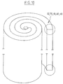
- the assembly step consists in winding on itself a complex based on the extruded element, comprising the electrolyte layer and two electrodes, such as a cathode and an anode, as well as preferably metal sheets or metallized plastic sheets, as shown in FIG. 10.
- the assembly shown in FIG. 11 is obtained by assembling two extruded complexes corresponding to the profile of FIG. 1.
- the electrolytes 10 of the two complexes are backed up so that the anode 70 and the cathode 80 are accessible on opposite edges of the winding.
- a metallized film 92, 90 is deposited on the exterior respectively of the anode 70 and of the cathode 80.
- the metallized film 92, 90 completely covers the anode 70 and the cathode 80 respectively. It is extended opposite the electrolyte 10 by a marginal strip of electrically insulating film 93, 91.
- the assembly shown in Figure 12 is obtained by assembling two extruded complexes corresponding to the profile of Figure 2.
- the electrolytes 10 of the two complexes are backed so that the anode 70 and the cathode 80 are placed on opposite sides of the winding.
- a metallized film 92, 90 is deposited on the outside of the anode 70 and of the cathode 80 respectively.
- the metallized film 92, 90 completely covers the anode 70 and the cathode 80 respectively as well as one of the marginal zones of the electrolytes respectively adjacent to opposite wafers. It is extended opposite the other marginal zone of the electrolyte 10 by an electrically insulating film strip 93, 91.
- the electrically insulating marginal strip 93 is adjacent to one of the edges of the winding
- the strip electrically insulating marginal 91 is adjacent to the other edge.
- the assembly shown in Figure 13 is obtained using an extruded complex corresponding to the profile of Figure 3.
- a metallized film 92, 90 is deposited on the outside of the anode 70 and the cathode 80 respectively.
- the metallized film 92, 90 completely covers the anode 70 and the cathode 80 respectively. It is extended opposite the electrolyte 10 by a marginal strip of electrically insulating film 93, 91.
- the assembly shown in FIG. 14 is obtained by assembling two extruded complexes corresponding to the profile of FIG. 3.
- One of the electrodes 50 of a first complex is placed in contact with the electrode 50 of the same kind of the second complex so that the anode 70 and cathode 80 are accessible on opposite edges of the winding.
- a metallized film 92, 90 is deposited on the outside of the second electrode.
- the metallized film 92, 90 completely covers this second electrode. It is extended opposite the electrolyte 10 by a marginal strip of electrically insulating film 93, 91.
- the assembly shown in FIG. 15 is obtained using an extruded complex corresponding to the profile of FIG. 4.
- a metallized film 92, 90 is deposited on the outside of the anode 70 and of the cathode 80 respectively.
- the metallized film 92, 90 completely covers the anode 70 and the cathode 80 respectively. It is extended opposite the electrolyte 10 by a marginal strip of electrically insulating film 93, 91.
- the assembly shown in FIG. 16 is obtained using an extruded complex corresponding to the profile of FIG. 6.
- Two metallized films 92, 90 are deposited respectively on the external electrode.
- the metallized films 92, 90 completely cover the external electrode. They are extended opposite the electrolyte 10 by a marginal strip of electrically insulating film 93, 91.
- the assembly shown in Figure 17 is obtained using an extruded complex corresponding to the profile of Figure 5.
- Two metallized films 92, 90 are deposited respectively on the outer electrode.
- the metallized films 92, 90 completely cover the external electrode. They are extended opposite the electrolyte 10 by a marginal strip of electrically insulating film 93, 91.
- the cylindrical unit elements obtained by winding can be crushed and treated as pancakes.
- the electrical connections are made at the edges of the windings by molten metal or alloy deposition with a low melting point and good electrical conductivity. It can be a deposit with an electric gun.
- the metallized films 90 are preferably polypropylene films with a thickness of 15 to 25 ⁇ m nickel metallized with a thickness of 20 to 100 nm by deposition by evaporation by Joule effect or by electron gun.
- the single films 92 are preferably polypropylene films with a thickness of 15 to 25 ⁇ m.
- the lithium electrode can be produced by cold calendering, coating of the lithium liquid phase or vacuum deposition.
- This first example consists first of all in co-extruding the electrolyte 10 and the cathode 80 along the profile in accordance with FIG. 1 with the following compositions: Cathode composition: MnO 2 75% by mass Amorphous 7% by mass Polyethylene oxide 9% by mass Polyethylene glycol 6% by mass LICF 3 SO 3 3% by mass Electrolyte composition Polyethylene oxide 85% by mass Polyolefin wax 5% by mass LICF 3 SO 3 10% by mass
- the assembly 10/80 thus obtained is deposited on the cathode side 80 on a sheet 90 of polypropylene metallized with nickel 100 with a margin of 5mm not metallized on the electrolyte side, as seen in FIG. 18A.
- a laminated lithium sheet is prepared to form the anode 70.
- a lithium strip 300 ⁇ m thick is brought to 100 ⁇ m by cold rolling between two polypropylene shims 104 of thickness 100 ⁇ m and of 5mm wide.
- the complex obtained is calendered by keeping a shim of thickness 104 and by placing a polypropylene film 92 on the anode in lithium 70, as seen in Figure 18B.
- the wedge 104 is positioned so that anode 70 and cathode 80 are accessible on different wafers.
- the 92/70/10/80/100/90 complex is wound and electrical nickel connections are placed on each side or section of the winding by deposition with an electric gun.
- This second example firstly consists in co-extruding the electrolyte 10 and the cathode 80 along the profile in accordance with FIG. 1 with the following compositions: Cathode composition: MnO 2 78% by mass VS 4% by mass Graphite 1% by mass Polyethylene oxide PM 600000 6% by mass Polyethylene glycol 6% by mass LiCF 3 SO 3 5% by mass Electrolyte composition Polyethylene oxide 75% by mass Polyolefin wax 5% by mass LiCF 3 SO 3 10% by mass MgO 10% by mass
- This first cathode 80 / electrolyte 10 complex is deposited on a stainless metal sheet 90 such as nickel with a thickness of 5 ⁇ m as shown in FIG. 19A.
- a two-layer assembly of lithium anode 70 and of electrolyte 10 in accordance with the profile of FIG. 1 is produced.
- This assembly is preferably produced by cold extrusion.
- This assembly 10/70 is then deposited on the anode side 70 on a film 92 of nickel metallized polypropylene 106, with a thickness of 12 ⁇ m.
- the complexes are calendered.
- the third example consists first of all in making a three-layer cathode 80 / electrolyte 10 / anode 70 coextrusion, in accordance with the profile in FIG. 3, as shown in FIG. 20, with the following compositions:
- This 70/10/80 extruded three-layer complex is deposited, cathode side 80 on a polyethylene film 90 metallized at 100 by a layer of metal or stainless alloy, for example nickel or stainless steel, with margin 102, electrolyte side.
- the foregoing examples relate to the manufacture of a generator.
- the two electrodes placed respectively on either side of the electrolyte 10 are of identical nature.
- the fourth example consists first of all in carrying out a two-layer extrusion of an electrolyte layer 10 of the same composition as Example 1, on an electrode layer 75 of the following composition, according to the profile of FIG. 1: Amorphous 10% by mass C large specific surface 30% by mass Polyethylene oxide 40% by mass Polyethylene glycol 10% by mass LiCF 3 SO 3 10% by mass
- the extruded bilayer complex thus obtained 10/75 is deposited on the electrode side 75 on a film 90 of nickel metallized polypropylene 100 with a margin 102 of 5mm on the electrolyte side, as shown in FIG. 21A.
- the fifth example firstly consists in carrying out a three-layer extrusion of electrode 75 / electrolyte 10 / electrode 75 according to a profile in accordance with FIG. 3, with the following compositions: Electrode composition: Amorphous 15% by mass C large specific surface 35% by mass Binder (polyethylene oxide or PVDF) 48% by mass Processing Aid 2% by mass Polyethylene oxide electrolyte composition 100%
- the 75/10/75 extruded three-layer complex is deposited between two films 110 of polyethylene or polypropylene metallized stainless steel or nickel 112, with margin 114 on the electrolyte side.
- the whole is calendered and wound.
- the elements are impregnated with an organic solvent in which 1 salt is dissolved - for example a solvent of propylene carbonate and a salt such as bi (trifluoro sulfonate) imide of Li at 45% by mass.
- an organic solvent in which 1 salt is dissolved - for example a solvent of propylene carbonate and a salt such as bi (trifluoro sulfonate) imide of Li at 45% by mass.
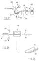
- the method according to the present invention comprises a first step which consists in the preparation of an electrode 80, cathode or anode, by CAST calendering extrusion.
- a CAST extrusion process consists in receiving the extruded material, at the outlet of the die, on a support, preferably heated, adapted to allow drawing of the extruded material.
- the general reference 200 shows the extruder for this electrode 80.
- the electrode film 80 is protected on its two main faces by two protective sheets 210, 212, or a protective sheet 210 and a current collector 212.
- the protective sheets 210, 212 are preferably formed from polyester.
- the sheet serving as a current collector is preferably formed from a metallized plastic sheet.
- the electrode 80 thus protected by the sheets 210, 212 is preferably then subjected to a calendering operation, in a calendering station 220, with heating between 30 and 50 ° C of the two cylinders, or only one of the calendering 220.
- the calendering operation can be carried out in one or more stages. It is preferably suitable for obtaining a thin layer electrode 80 between 170 ⁇ m and 40 ⁇ m.
- the second step of this variant consists, after removing the protective sheets 210, 212, as shown diagrammatically in FIG. 24, in partially coating the electrode 80 with the electrolyte 10, during an extrusion operation carried out through a sector shown diagrammatically under reference 230 in FIG. 24.
- one of the sheets 210, 212 is formed of a current collector
- this current collector is held on the electrode 80 through the die 230.
- FIG. 25 which represents a sectional view of the assembly obtained at the outlet of the die 230
- the electrolyte 10 has been shown diagrammatically in the form of an L comparable to the drawing in FIG. 1. This representation should not however be considered limiting.
- this variant embodiment illustrated in FIGS. 23 and 24 can be used to form an electrolyte in accordance with any of the sections previously described and illustrated in the preceding figures.
- the second electrode 70 anode or cathode, can be deposited on the assembly obtained at the outlet of the die 230 by any suitable means.
- the second electrode 70 can for example be co-extruded with the electrolyte 10 in the die 230, or also produced separately and deposited on the complex 10, 80, as described above.
Landscapes
- Manufacturing & Machinery (AREA)
- Chemical & Material Sciences (AREA)
- Chemical Kinetics & Catalysis (AREA)
- Electrochemistry (AREA)
- General Chemical & Material Sciences (AREA)
- Engineering & Computer Science (AREA)
- Secondary Cells (AREA)
- Electric Double-Layer Capacitors Or The Like (AREA)
- Primary Cells (AREA)
- Battery Electrode And Active Subsutance (AREA)
- Laminated Bodies (AREA)
- Extrusion Moulding Of Plastics Or The Like (AREA)
- Electrolytic Production Of Non-Metals, Compounds, Apparatuses Therefor (AREA)
Claims (45)
- Verfahren zur Herstellung einer elektrochemischen Mehrschichten-Einheit, dadurch gekennzeichnet, daß es die folgenden Stufen umfaßt:- Extrudieren eines Elements, das einen Elektrolytfilm (10) auf Basis eines lonenleiter-Polymers und mindestens einen Elektrodenfilm (70, 80) umfaßt, mit einem entsprechenden Spritzmundstück in der Weise, daß die Elektrode (70, 80) auf mindestens einer Hauptoberfläche (1, 2) des extrudierten Elements und höchstens auf einem Abschnitt (3, 4) dieses Elements zugänglich ist,- Zusammenrollen (Aufwickeln) eines Komplexes auf Basis des obengenannten extrudierten Elements, der die Elektrolytschicht (10) und zwei Elektroden (70, 80; 75), die jeweils beiderseits des Elektrolyten (10) angeordnet sind, beispielsweise eine Kathode und eine Anode umfaßt, in Form einer Struktur, die auf unterschiedlichen Oberflächen ihre Abschnitte jeweils elektrische Kontaktstellen mit den beiden Elektroden aufweist, und- Durchführung einer Metallisierung (Galvanisierung) dieser Abschnittsflächen der Struktur.
- Verfahren nach Anspruch 1, dadurch gekennzeichnet, daß eine der Elektroden (70, 80) eine Anode bildet, während die zweite Elektrode eine Kathode (80, 70) bildet, und daß die elektrochemische Einheit einen elektrischen Stromgenerator darstellt.
- Verfahren nach Anspruch 1, dadurch gekennzeichnet, daß die beiden Elektroden (75) von gleicher Art sind und daß die elektrochemische Einheit einen Superkondensator darstellt.
- Verfahren nach einem der Ansprüche 1 bis 3, dadurch gekennzeichnet, daß es darin besteht, den Elektrolyffilm (10) mit einer daran angrenzenden Elektrode (70, 80; 75) in Form eines Doppelschichten-Komplexes zu coextrudieren.
- Verfahren nach einem der Ansprüche 1 bis 3, dadurch gekennzeichnet, daß es darin besteht, den Elektrolytfilm (10) mit jeweils zwei daran angrenzenden Elektroden (70, 80; 75) in Form eines Dreischichten-Komplexes zu koextrudieren.
- Verfahren nach einem der Ansprüche 1 bis 4, dadurch gekennzeichnet, daß es darin besteht, durch Biextrusion einen Elektrolyffilm (10) herzustellen, der ein L-Profil aufweist und eine Hauptoberfläche (1) der extrudierten Folie sowie einen der beiden Abschnitte (3) derselben vollständig bedeckt,der auf diese Weise in einen Rand der zweiten Hauptoberfläche (2) einmündet, wobei die coextrudierte Elektrode (50) auf einem Teil der zweiten Hauptoberfläche (2) und auf einem Teil des zweiten Abschnitts (4) der Folie zugänglich ist.
- Verfahren nach einem der Ansprüche 1 bis 4, dadurch gekennzeichnet, daß es darin besteht, durch Biextrusion einen Elektrolyffilm (10) herzustellen, der ein U-Profil aufweist und eine Hauptoberfläche (1) der extrudierten Folie sowie die beiden Abschnitte (3, 4) derselben vollständig bedeckt, wobei die coextrudierte Elektrode (50) auf einem Teil der zweiten Hauptoberfläche (2) zwischen den Elektrolyt-Rändern zugänglich ist.
- Verfahren nach einem der Ansprüche 1 bis 5, dadurch gekennzeichnet, daß es darin besteht, durch Triextrusion einen Elektrolyffilm (10) herzustellen, der eine innere Seele (11) umfaßt, die sich über die gesamte Breite der extrudierten Folie erstreckt und an ihren jeweiligen Enden Verlängerungen (12, 13) aufweist, die einen Teil der jeweiligen Abschnitt (3, 4) bedecken und jeweils in einen Rand der Hauptoberflächen (1, 2) der extrudierten Folie einmünden, wobei die Elektrodenschichten (50, 60) jeweils beiderseits der inneren Seele (11) angeordnet sind und auf diese Weise auf einem Teil der ersten und der zweiten Hauptoberflächen (1, 2) sowie auf einem Teil der Abschnitte (3 und 4) der extrudierten Folie zugänglich sind.
- Verfahren nach einem der Ansprüche 1 bis 5, dadurch gekennzeichnet, daß es darin besteht, daß man durch Triextrusion einen Elektrodenfilm herstellt, der ein H-Profil aufweist und eine innere Seel (11) besitzt, die sich über die gesamte Breite der extrudierten Folie erstreckt und an ihren jeweiligen Enden Verlängerungen (12, 13, 14, 15) aufweist, welche die jeweiligen Abschnitte (3, 4) integral bedecken und in einem Rand jeder der Hauptoberflächen (2, 1) münden, wobei die Elektrodenschichten (50, 60) jeweils beiderseits der inneren Seele (11) angeordnet sind und jeweils auf einem Teil der ersten und der zweiten Hauptoberflächen (1, 2) zwischen den Verlängerungen (12, 13, 14 und 15) des Elektrolyten zugänglich sind.
- Verfahren nach einem der Ansprüche 1 bis 5, dadurch gekennzeichnet, daß es darin besteht, durch Triextrusion einen Elektrolytfilm (10) herzustellen, der ein generelles U-Profil aufweist, das eine Seele (16) besitzt, die sich senkrecht zu den Hauptoberflächen (1, 2) des extrudierten Films und zwei untereinander parallelen Zweigen (Schenkeln) (17, 18), die parallel zu den Hauptoberflächen (1, 2) sind, von diesen jedoch einen Abstand haben, erstreckt, wobei die freien Enden der Zweige (Schenkel) (17, 18), die der Seele (16) gegenüber liegen, mit Verlängerungen (19, 20) nach innen ausgestattet sind, die auf den Hauptoberflächen (1, 2) zugänglich sind, und die beiden Elektroden (50, 60) jeweils im Innern des zwischen den Zweigen (Schenkeln) (17, 18) definierten Raumes und auf dem äußeren desselben angeordnet sind, um jeweils auf den verschiedenen Abschnitten des extrudierten Films zugänglich zu sein.
- Verfahren nach Anspruch 10, dadurch gekennzeichnet, daß die Seele (16) der Elektrolytschicht (10) auf einem (4) der Abschnitte der extrudierten Folie zugänglich ist.
- Verfahren nach Anspruch 10, dadurch gekennzeichnet, daß die Seele (16) des Elektrolyten (10) einen Abstand von dem Abschnitt (4) der extrudierten Folie hat.
- Verfahren nach einem der Ansprüche 10 und 11, dadurch gekennzeichnet, daß die Verlängerungen (19, 20) auf dem zweiten Abschnitt (3) der extrudierten Folie zugänglich sind.
- Verfahren nach einem der Ansprüche 10 und 12, dadurch gekennzeichnet, daß die Verlängerungen (19, 20) einen Abstand von dem zweiten Abschnitt (3) der extrudierten Folie haben.
- Verfahren nach einem der Ansprüche 6 bis 9, dadurch gekennzeichnet, daß ein elektrisch isolierender Separator zwischen zwei aneinandergrenzenden Komplexen eingefügt ist.
- Verfahren nach einem der Ansprüche 10 bis 14, dadurch gekennzeichnet, daß mindestens zwei Komplexe ohne dazwischenliegendem elektrisch isolierendem Separator aneinandergefügt sind.
- Verfahren nach einem der Ansprüche 1 bis 16, dadurch gekennzeichnet, daß der Elektrolytfilm (10) ein mit einem Lithiumsalz kombiniertes Polymermaterial umfaßt.
- Verfahren nach Anspruch 17, dadurch gekennzeichnet, daß das Lithiumsalz durch Mischen oder Aufpfropfen mit dem Polymermaterial kombiniert wird.
- Verfahren nach einem der Ansprüche 17 oder 18, dadurch gekennzeichnet, daß der Elektrolyffilm außerdem ein als Gleitmittel dienendes Wachs, ein flammwidrig machendes Mittel, ein Füllstoff-Dispergiermittel und/oder ein Mittel zur Erleichterung der Extrusion enthält.
- Verfahren nach Anspruch 19, dadurch gekennzeichnet, daß die Menge des Wachses in dem Elektrolytfilm in der Größenordnung von einigen Massenprozent liegt.
- Verfahren nach einem der Ansprüchen 19 und 20, dadurch gekennzeichnet, daß das Wachs ausgewählt wird aus der Gruppe, welche die Polyolefine, z.B. ein amorphes Ethylen-Terpolymer oder ein Polyethylen mit geringer Viskosität, und die Amide umfaßt.
- Verfahren nach einem der Ansprüchen 1 bis 21, dadurch gekennzeichnet, daß eine der Elektroden aus einer Anode auf Lithiumbasis besteht.
- Verfahren nach Anspruch 22, dadurch gekennzeichnet, daß die Lithiumanode extrudiert wird.
- Verfahren nach Anspruch 22, dadurch gekennzeichnet, daß die Lithiumanode durch kaltes Kalandrieren, durch Beschichten in wäßriger Phase oder durch Abscheidung unter Vakuum hergestellt wird.
- Verfahren nach einem der Ansprüche 1 bis 24, dadurch gekennzeichnet, daß eine der Elektroden (80) aus einer Kathode besteht, die im Kontakt steht mit einer Metallfolie, die mit einer isolierenden Folie verbunden ist, oder mit einem metallisierten (galvanisierten) Film oder mit einer Metallschicht, die mit einer isolierenden Folie verbunden ist.
- Verfahren nach einem der Ansprüche 1 bis 25, dadurch gekennzeichnet, daß eine der Elektroden (70) aus einer Anode besteht, die im Kontakt steht mit einer Metallfolie, die mit einer isolierenden Folie verbunden ist, oder mit einem metallisierten Film oder mit einer Metallschicht, die mit einer isolierenden Folie verbunden ist.
- Verfahren nach einem der Ansprüche 1 bis 26, dadurch gekennzeichnet, daß eine der Elektroden aus einer Anode (70) im Kontakt mit einem Nichtleiterfilm (90) besteht.
- Verfahren nach einem der Ansprüche 1 bis 27, dadurch gekennzeichnet, daß der Komplex einen Elektrolytfilm umfaßt, der zwei Elektroden (70, 80) zugeordnet ist und gegebenenfalls Metallfolien oder metallisierte Folien aufweist, die eine Dicke zwischen 100 und 500 µm haben.
- Verfahren nach einem der Ansprüche 1 bis 28, dadurch gekennzeichnet, daß der Komplex kalandriert wird.
- Verfahren nach Anspruch 29, dadurch gekennzeichnet, daß der Komplex kalt kalandriert wird.
- Verfahren nach einem der Ansprüche 1 bis 30, dadurch gekennzeichnet, daß es darin besteht, zwei symmetrische Doppelschichten-Komplexe, die jeweils coextrudiert worden sind, aufzuwickeln, wobei man die Elektrolytschichten (10) so anordnet, daß die beiden Elektroden auf den Oberflächen und/oder gegenüberliegenden Abschnitten der Einheit zugänglich sind.
- Verfahren nach Anspruch 31, dadurch gekennzeichnet, daß die coextrudierten Doppelschichten-Einheiten einem der Ansprüche 6 oder 7 entsprechen.
- Verfahren nach einem der Ansprüche 1 bis 30, dadurch gekennzeichnet, daß es darin besteht, zwei symmetrische Doppelschichten-Komplexe aufzuwickeln, indem man zwei Elektrodenschichten gleicher Art aneinanderlegt.
- Verfahren nach Anspruch 33, dadurch gekennzeichnet, daß diese Komplexe dem Anspruch 8 entsprechen.
- Verfahren nach einem der Ansprüche 1 bis 34, dadurch gekennzeichnet, daß eine elektrisch leitende Folie (90,92), die mindestens eine Rand-Bordüre aus einem elektrisch isolierenden Material (91, 93) enthält, auf jeder Hauptoberfläche des Komplexes vor dem Einrollen desselben abgeschieden wird.
- Verfahren nach einem der Ansprüche 1 bis 35, dadurch gekennzeichnet, daß es die folgenden Stufen umfaßt:- Extrudieren einer Kathode (80) auf einen metallisierten Filmträger (90) und anschließendes Extrudieren des Elektrolyten (10) auf diese Einheit (80, 90),- Extrudieren einer Lithiumanode (70) auf einen Trägerfilm (92) und- Kalandrieren der beiden oben erhaltenen Komplexe.
- Verfahren nach einem der Ansprüche 1 bis 35, dadurch gekennzeichnet, daß es die folgenden Stufen umfaßt:- Coextrudieren einer Kathode (80) und des Elektrolyten (10) auf einen metallisierten Trägerfilm (90),- Extrudieren einer Lithiumanode (70) auf einen Trägerfilm (92) und- Kalandrieren der beiden oben erhaltenen Komplexe.
- Verfahren nach einem der Ansprüche 1 bis 35, dadurch gekennzeichnet, daß es die folgenden Stufen umfaßt:- Extrudieren einer Kathode (80) auf einen metallisierten Trägerfilm (90),- Coextrudieren einer Lithiumanode (70) und des Elektrolyten (10) auf einen Trägerfilm (92) und- Kalandrieren der beiden oben erhaltenen Komplexe.
- Verfahren nach einem der Ansprüche 1 bis 35, dadurch gekennzeichnet, daß es die folgenden Stufen umfaßt:- Coextrudieren einer Kathode aus einem Verbundmaterial (80), der Elektrode (10) und einer Lithiumanode (70) auf einen metallisierten Trägerfilm (90) oder auf den Trägerfilm (92),- Aufkalandrieren dieser Einheit auf einen Trägerfilm (92) oder einen metallisierten Trägerfilm (90).
- Verfahren nach einem der Ansprüche 1 bis 35, dadurch gekennzeichnet, daß es die folgenden Stufen umfaßt:- Herstellung einer Elektrode (80) durch CAST-Extrusion unter Schützen der beiden Hauptoberflächen der Elektrode (80) beim Austritt aus dem Extruder durch zwei Schutzfolien (210, 212) oder eine Schutzfolie (210) und einen Stromkollektor (212),- Extrudieren des Elektrolyten (10) auf die so erhaltene Einheit, nach dem die Schutzfolie(n) (210, 212) abgezogen worden ist (sind).
- Verfahren nach Anspruch 40, dadurch gekennzeichnet, daß die Schutzfolien (210, 212) aus Polyester hergestellt sind.
- Verfahren nach einem der Ansprüche 40 oder 41, dadurch gekennzeichnet, daß es außerdem einen Arbeitsgang umfaßt, der darin besteht, die geschützte Elektrode (80) vor Durchführung der Extrusion des Elektrolyten (10) zu kalandrieren.
- Verfahren nach einem der Ansprüche 40 bis 42, dadurch gekennzeichnet, daß die zweite Elektrode (70) auf der nach der Extrusion des Elektrolyten (10) erhaltenen Einheit abgeschieden wird durch Coextrusion mit diesem Elektrolyten (10) oder durch getrennt durchgeführte Abscheidung der zweiten Elektrode.
- Verfahren nach einem der Ansprüche 1 bis 43, dadurch gekennzeichnet, daß es außerdem eine Stufe umfaßt, die darin besteht, die in Form von Scheiben erhaltenen Wicklungen flachzudrücken.
- Verfahren nach einem der Ansprüche 1 bis 44, dadurch gekennzeichnet, daß die elektrischen Verbindungen auf den Abschnitten der Struktur erhalten werden durch Abscheidung von Metall oder einer Legierung mit niedrigem Schmelzpunkt und guter elektrischer Leiffähigkeit aus der geschmolzenen Phase, beispielsweise durch Abscheidung mit einer elektrischen Pistole.
Applications Claiming Priority (2)
| Application Number | Priority Date | Filing Date | Title |
|---|---|---|---|
| FR9313635A FR2712733B1 (fr) | 1993-11-16 | 1993-11-16 | Procédé de fabrication d'un ensemble électrochimique multicouche comprenant un électrolyte entre deux électrodes et ensemble ainsi réalisé. |
| FR9313635 | 1993-11-16 |
Publications (2)
| Publication Number | Publication Date |
|---|---|
| EP0657951A1 EP0657951A1 (de) | 1995-06-14 |
| EP0657951B1 true EP0657951B1 (de) | 1997-06-11 |
Family
ID=9452884
Family Applications (1)
| Application Number | Title | Priority Date | Filing Date |
|---|---|---|---|
| EP94402564A Expired - Lifetime EP0657951B1 (de) | 1993-11-16 | 1994-11-14 | Verfahren zur Herstellung von mehrschichtiger elektrochemischer Bauelemente, die zwischen zwei Elektroden ein Elektrolyt enthalten und auf dieser Weise hergestellte Bauelemente |
Country Status (9)
| Country | Link |
|---|---|
| US (1) | US5593462A (de) |
| EP (1) | EP0657951B1 (de) |
| JP (1) | JP3580871B2 (de) |
| AT (1) | ATE154470T1 (de) |
| DE (1) | DE69403761T2 (de) |
| DK (1) | DK0657951T3 (de) |
| ES (1) | ES2105571T3 (de) |
| FR (1) | FR2712733B1 (de) |
| GR (1) | GR3024681T3 (de) |
Cited By (1)
| Publication number | Priority date | Publication date | Assignee | Title |
|---|---|---|---|---|
| WO2025011825A1 (de) | 2023-07-10 | 2025-01-16 | Troester Gmbh & Co. Kg | Verfahren zur herstellung eines lösungsmittelfreien elektrodencompounds sowie ein verfahren zum ausbringen einer vorlage mittels einer austragsvorrichtung |
Families Citing this family (60)
| Publication number | Priority date | Publication date | Assignee | Title |
|---|---|---|---|---|
| CN1184435A (zh) | 1995-05-12 | 1998-06-10 | 唐纳森公司 | 滤清器装置 |
| FR2755795A1 (fr) * | 1996-11-12 | 1998-05-15 | Electricite De France | Collecteur de courant pour electrode positive et eventuellement electrode negative pour un ensemble electrochimique multicouche et pour bobinage ainsi obtenu |
| KR19980060825A (ko) * | 1996-12-31 | 1998-10-07 | 손욱 | 상부 절연부재 겸 세퍼레이터 및 이를 채용하는 원통형 알칼리 2차 전지 |
| US6235065B1 (en) | 1998-10-27 | 2001-05-22 | Alcatel | Room temperature lamination of Li-ion polymer electrodes |
| JP4714952B2 (ja) * | 1998-10-30 | 2011-07-06 | ソニー株式会社 | リチウムイオンポリマ二次電池及びその製造装置並びに製造方法 |
| EP1161774A2 (de) * | 1999-02-19 | 2001-12-12 | Amtek Research International LLC | Elektrisch leitfähige, freistehende mikroporöse polymerschicht |
| US6503432B1 (en) * | 2000-03-02 | 2003-01-07 | E. I. Du Pont De Nemours And Company | Process for forming multilayer articles by melt extrusion |
| US6627252B1 (en) | 2000-05-12 | 2003-09-30 | Maxwell Electronic Components, Inc. | Electrochemical double layer capacitor having carbon powder electrodes |
| US6631074B2 (en) | 2000-05-12 | 2003-10-07 | Maxwell Technologies, Inc. | Electrochemical double layer capacitor having carbon powder electrodes |
| US6589299B2 (en) | 2001-02-13 | 2003-07-08 | 3M Innovative Properties Company | Method for making electrode |
| DE10118639B4 (de) * | 2001-04-12 | 2007-06-14 | Dilo Trading Ag | Verfahren zur kontinuierlichen Herstellung von Trilaminaten für Polymer-Lithium Batterien |
| JP4873281B2 (ja) * | 2001-04-20 | 2012-02-08 | 住友電気工業株式会社 | リチウム電池負極の製造方法 |
| US7233097B2 (en) * | 2001-05-22 | 2007-06-19 | Sri International | Rolled electroactive polymers |
| US8021775B2 (en) | 2001-07-13 | 2011-09-20 | Inventek Corporation | Cell structure for electrochemical devices and method of making same |
| US7195840B2 (en) * | 2001-07-13 | 2007-03-27 | Kaun Thomas D | Cell structure for electrochemical devices and method of making same |
| US6643119B2 (en) | 2001-11-02 | 2003-11-04 | Maxwell Technologies, Inc. | Electrochemical double layer capacitor having carbon powder electrodes |
| US6939383B2 (en) * | 2002-05-03 | 2005-09-06 | 3M Innovative Properties Company | Method for making electrode |
| WO2004051769A2 (en) * | 2002-12-02 | 2004-06-17 | Avestor Limited Partnership | Co-extrusion manufacturing process of thin film electrochemical cell for lithium polymer batteries and apparatus therefor |
| US20060147712A1 (en) * | 2003-07-09 | 2006-07-06 | Maxwell Technologies, Inc. | Dry particle based adhesive electrode and methods of making same |
| US20050266298A1 (en) * | 2003-07-09 | 2005-12-01 | Maxwell Technologies, Inc. | Dry particle based electro-chemical device and methods of making same |
| US20070122698A1 (en) | 2004-04-02 | 2007-05-31 | Maxwell Technologies, Inc. | Dry-particle based adhesive and dry film and methods of making same |
| US7295423B1 (en) | 2003-07-09 | 2007-11-13 | Maxwell Technologies, Inc. | Dry particle based adhesive electrode and methods of making same |
| US20050250011A1 (en) * | 2004-04-02 | 2005-11-10 | Maxwell Technologies, Inc. | Particle packaging systems and methods |
| US7791860B2 (en) | 2003-07-09 | 2010-09-07 | Maxwell Technologies, Inc. | Particle based electrodes and methods of making same |
| US20100014215A1 (en) * | 2004-04-02 | 2010-01-21 | Maxwell Technologies, Inc. | Recyclable dry particle based electrode and methods of making same |
| US7342770B2 (en) * | 2003-07-09 | 2008-03-11 | Maxwell Technologies, Inc. | Recyclable dry particle based adhesive electrode and methods of making same |
| US7508651B2 (en) * | 2003-07-09 | 2009-03-24 | Maxwell Technologies, Inc. | Dry particle based adhesive and dry film and methods of making same |
| US7352558B2 (en) * | 2003-07-09 | 2008-04-01 | Maxwell Technologies, Inc. | Dry particle based capacitor and methods of making same |
| JP5079329B2 (ja) * | 2003-08-01 | 2012-11-21 | バシウム・カナダ・インコーポレーテッド | ポリマー電池のための正極材料及びその製造方法 |
| US7920371B2 (en) | 2003-09-12 | 2011-04-05 | Maxwell Technologies, Inc. | Electrical energy storage devices with separator between electrodes and methods for fabricating the devices |
| JP2005116762A (ja) * | 2003-10-07 | 2005-04-28 | Fujitsu Ltd | 半導体装置の保護方法及び半導体装置用カバー及び半導体装置ユニット及び半導体装置の梱包構造 |
| US7495349B2 (en) | 2003-10-20 | 2009-02-24 | Maxwell Technologies, Inc. | Self aligning electrode |
| US7090946B2 (en) * | 2004-02-19 | 2006-08-15 | Maxwell Technologies, Inc. | Composite electrode and method for fabricating same |
| US7384433B2 (en) | 2004-02-19 | 2008-06-10 | Maxwell Technologies, Inc. | Densification of compressible layers during electrode lamination |
| US7227737B2 (en) | 2004-04-02 | 2007-06-05 | Maxwell Technologies, Inc. | Electrode design |
| US20060246343A1 (en) * | 2004-04-02 | 2006-11-02 | Maxwell Technologies, Inc. | Dry particle packaging systems and methods of making same |
| US20060137158A1 (en) * | 2004-04-02 | 2006-06-29 | Maxwell Technologies, Inc. | Dry-particle packaging systems and methods of making same |
| US7492571B2 (en) * | 2004-04-02 | 2009-02-17 | Linda Zhong | Particles based electrodes and methods of making same |
| US8734983B2 (en) * | 2004-04-14 | 2014-05-27 | Inventek Corporation | Housing for electrochemical devices |
| US7245478B2 (en) | 2004-08-16 | 2007-07-17 | Maxwell Technologies, Inc. | Enhanced breakdown voltage electrode |
| US7531012B2 (en) * | 2004-10-21 | 2009-05-12 | Bathium Canada Inc. | Thin film electrochemical cell for lithium polymer batteries and manufacturing method therefor |
| US7492574B2 (en) | 2005-03-14 | 2009-02-17 | Maxwell Technologies, Inc. | Coupling of cell to housing |
| US7440258B2 (en) | 2005-03-14 | 2008-10-21 | Maxwell Technologies, Inc. | Thermal interconnects for coupling energy storage devices |
| CN101005132A (zh) | 2005-12-22 | 2007-07-25 | 格瑞巴奇有限公司 | 制造用于锂/卤氧化物电化学电池的阴极集流体的装置和方法 |
| US7647210B2 (en) * | 2006-02-20 | 2010-01-12 | Ford Global Technologies, Llc | Parametric modeling method and system for conceptual vehicle design |
| US8518573B2 (en) * | 2006-09-29 | 2013-08-27 | Maxwell Technologies, Inc. | Low-inductive impedance, thermally decoupled, radii-modulated electrode core |
| US20080201925A1 (en) | 2007-02-28 | 2008-08-28 | Maxwell Technologies, Inc. | Ultracapacitor electrode with controlled sulfur content |
| FR2915626B1 (fr) | 2007-04-24 | 2010-10-29 | Batscap Sa | Module pour ensemble de stockage d'energie electrique |
| FR2916306B1 (fr) | 2007-05-15 | 2009-07-17 | Batscap Sa | Module pour ensembles de stockage d'energie electrique permettant la detection du vieillissement desdits ensembles. |
| JP5602626B2 (ja) | 2007-06-29 | 2014-10-08 | アーティフィシャル マッスル,インク. | 感覚性フィードバック用途のための電気活性ポリマートランスデューサー |
| EP2239793A1 (de) | 2009-04-11 | 2010-10-13 | Bayer MaterialScience AG | Elektrisch schaltbarer Polymerfilmaufbau und dessen Verwendung |
| TWI542269B (zh) | 2011-03-01 | 2016-07-11 | 拜耳材料科學股份有限公司 | 用於生產可變形聚合物裝置和薄膜的自動化生產方法 |
| KR20140019801A (ko) | 2011-03-22 | 2014-02-17 | 바이엘 인텔렉쳐 프로퍼티 게엠베하 | 전기활성 중합체 작동기 렌티큘라 시스템 |
| EP2828901B1 (de) | 2012-03-21 | 2017-01-04 | Parker Hannifin Corporation | Rolle-an-rolle-herstellungsverfahren zur herstellung selbstheilender elektroaktiver polymervorrichtungen |
| WO2013192143A1 (en) | 2012-06-18 | 2013-12-27 | Bayer Intellectual Property Gmbh | Stretch frame for stretching process |
| WO2014066576A1 (en) | 2012-10-24 | 2014-05-01 | Bayer Intellectual Property Gmbh | Polymer diode |
| US9590233B2 (en) | 2013-04-05 | 2017-03-07 | Duracell U.S. Operations, Inc. | Method of making a cathode |
| US10037850B2 (en) | 2014-12-18 | 2018-07-31 | 3M Innovative Properties Company | Multilayer film capacitor |
| KR20170032001A (ko) * | 2015-09-14 | 2017-03-22 | 주식회사 엘지화학 | 리튬금속 전극 및 이를 포함하는 리튬 이차전지 |
| US10686213B2 (en) * | 2017-05-18 | 2020-06-16 | Panasonic Intellectual Property Management Co., Ltd. | Battery |
Family Cites Families (11)
| Publication number | Priority date | Publication date | Assignee | Title |
|---|---|---|---|---|
| US2280789A (en) * | 1937-08-09 | 1942-04-28 | Joseph B Brennan | Electrolytic device |
| GB1094457A (en) * | 1965-11-27 | 1967-12-13 | Ferranti Ltd | Improvements relating to the manufacture of thermo-electric generators |
| GB1105227A (en) * | 1965-12-11 | 1968-03-06 | Varta Ag | A galvanic cell |
| DE2827851A1 (de) * | 1978-06-24 | 1980-03-27 | Schock & Co Gmbh | Bauprofilleiste, insbesondere profilleiste fuer die herstellung von fensterrahmen |
| JPS6067131A (ja) * | 1983-09-24 | 1985-04-17 | Nippon Valqua Ind Ltd | クラツチフエ−シングの製造方法 |
| GB8333388D0 (en) * | 1983-12-15 | 1984-01-25 | Raychem Ltd | Materials for electrical devices |
| NL8701778A (nl) * | 1987-07-28 | 1989-02-16 | Philips Nv | Elektrochemische cel. |
| US5132070A (en) * | 1990-08-17 | 1992-07-21 | Paul Marlene L | Process for the manufacture of composite parts |
| US5219673A (en) * | 1991-08-23 | 1993-06-15 | Kaun Thomas D | Cell structure for electrochemical devices and method of making same |
| FR2685122B1 (fr) * | 1991-12-13 | 1994-03-25 | Alcatel Alsthom Cie Gle Electric | Supercondensateur a base de polymere conducteur. |
| US5445906A (en) * | 1994-08-03 | 1995-08-29 | Martin Marietta Energy Systems, Inc. | Method and system for constructing a rechargeable battery and battery structures formed with the method |
-
1993
- 1993-11-16 FR FR9313635A patent/FR2712733B1/fr not_active Expired - Fee Related
-
1994
- 1994-11-14 DE DE69403761T patent/DE69403761T2/de not_active Expired - Lifetime
- 1994-11-14 ES ES94402564T patent/ES2105571T3/es not_active Expired - Lifetime
- 1994-11-14 EP EP94402564A patent/EP0657951B1/de not_active Expired - Lifetime
- 1994-11-14 AT AT94402564T patent/ATE154470T1/de not_active IP Right Cessation
- 1994-11-14 US US08/339,017 patent/US5593462A/en not_active Expired - Lifetime
- 1994-11-14 DK DK94402564.2T patent/DK0657951T3/da active
- 1994-11-15 JP JP28059594A patent/JP3580871B2/ja not_active Expired - Lifetime
-
1997
- 1997-09-10 GR GR970402327T patent/GR3024681T3/el unknown
Cited By (1)
| Publication number | Priority date | Publication date | Assignee | Title |
|---|---|---|---|---|
| WO2025011825A1 (de) | 2023-07-10 | 2025-01-16 | Troester Gmbh & Co. Kg | Verfahren zur herstellung eines lösungsmittelfreien elektrodencompounds sowie ein verfahren zum ausbringen einer vorlage mittels einer austragsvorrichtung |
Also Published As
| Publication number | Publication date |
|---|---|
| GR3024681T3 (en) | 1997-12-31 |
| JP3580871B2 (ja) | 2004-10-27 |
| DK0657951T3 (da) | 1998-01-05 |
| ES2105571T3 (es) | 1997-10-16 |
| DE69403761T2 (de) | 1998-01-15 |
| US5593462A (en) | 1997-01-14 |
| DE69403761D1 (de) | 1997-07-17 |
| EP0657951A1 (de) | 1995-06-14 |
| FR2712733A1 (fr) | 1995-05-24 |
| JPH07240208A (ja) | 1995-09-12 |
| FR2712733B1 (fr) | 1996-02-09 |
| ATE154470T1 (de) | 1997-06-15 |
Similar Documents
| Publication | Publication Date | Title |
|---|---|---|
| EP0657951B1 (de) | Verfahren zur Herstellung von mehrschichtiger elektrochemischer Bauelemente, die zwischen zwei Elektroden ein Elektrolyt enthalten und auf dieser Weise hergestellte Bauelemente | |
| EP2583332B1 (de) | Stromabnehmer mit integrierter dichtung sowie zweipolige batterie mit einem derartigen stromabnehmer | |
| CA2051614C (fr) | Collecteurs de courant pour generateurs electrochimiques securitaires, procedes de preparation et generateurs obtenus | |
| BE1008327A6 (fr) | Batterie bipolaire plomb-acide et procede de durcissement des plaques bipolaires a y utiliser. | |
| EP2870655B1 (de) | Stromabnehmer mit integrierter dichtungsvorrichtung, bipolare batterie mit solch einem stromabnehmer | |
| FR2943854A1 (fr) | Batterie bipolaire a fonctionnement ameliore | |
| EP3076453B1 (de) | Elektrochemische vorrichtung, wie mikrobatterie oder elektrochromsystem, die mit einer einkapselungsschicht umgeben ist, die eine abdichtfolie und eine klebefolie umfasst, und herstellungsverfahren einer solchen vorrichtung | |
| EP2320502B1 (de) | Aufbauverfahren einer Batterie vom Lithium-Ionen-Typ aus Dünnschichten | |
| WO1988010519A1 (fr) | Procede d'elaboration d'ensemble multicouche pour generateur electrochimique | |
| EP3649694B1 (de) | Verfahren zur herstellung eines elektrochemischen bündels einer metall-ionenbatterie mittels einer gelpolymerelektrolytmembran und zugehörige batterien | |
| EP0651453A1 (de) | Elektrochemische Zelle für Lithium-Polymerelektrolyt Batterien | |
| HUE035791T2 (en) | Laminating process | |
| FR2831331A1 (fr) | Procede de fabrication d'une micro-batterie | |
| EP0206903A1 (de) | Verfahren zur Herstellung von elektrolytischen Kondensatoren sowie durch dieses Verfahren hergestellter Kondensator | |
| FR3044169A1 (fr) | Batterie bipolaire lithium-ion | |
| EP2707916B1 (de) | Architektur mit stapelung von stromspeichernden und/oder stromerzeugenden elementen mit konfigurierbarer elektrischer leistung, verfahren zur herstellung einer solchen architektur | |
| EP3095147B1 (de) | Elektrochemischer akkumulator mit gehäuse und terminal bestehend aus einer aluminiumlegierung | |
| FR3096927A1 (fr) | Film conducteur composite pour la réalisation d'accumulateurs d'énergie électrique, procédé de réalisation d'un tel film, et accumulateur électrique utilisant un tel film. | |
| FR3112655A1 (fr) | Procédé et équipement de fabrication d’une cellule de batterie | |
| EP1964203B1 (de) | Verfahren zur herstellung einer brennstoffzelle mit im festelektrolyt integrierten stromkollektoren | |
| EP3482432B1 (de) | Metall-ion akkumulator mit hohe kapazität, wessen flexibilität für eine hohe gleichförmichkeit dient | |
| EP4175014B1 (de) | Stromabnehmer eines instrumentierungselements eines elektrochemischen systems mit durch wärmeversiegelung eines heissschmelzpolymers an einem elektrisch leitenden band gestützten elektrisch leitenden band. | |
| WO2022243243A1 (fr) | Elément électrochimique pour batterie, et batterie correspondante | |
| EP3327819B1 (de) | Metallionen-akkumulator mit einem stapel elektroden, gekennzeichnet durch eine hohe energiedichte und eine hohe kapazität | |
| EP4454047A1 (de) | Elektrochemisches bündel, batterieelement und zugehörige herstellungsverfahren |
Legal Events
| Date | Code | Title | Description |
|---|---|---|---|
| PUAI | Public reference made under article 153(3) epc to a published international application that has entered the european phase |
Free format text: ORIGINAL CODE: 0009012 |
|
| AK | Designated contracting states |
Kind code of ref document: A1 Designated state(s): AT BE CH DE DK ES FR GB GR IE IT LI LU MC NL PT SE |
|
| 17P | Request for examination filed |
Effective date: 19951113 |
|
| GRAG | Despatch of communication of intention to grant |
Free format text: ORIGINAL CODE: EPIDOS AGRA |
|
| 17Q | First examination report despatched |
Effective date: 19960805 |
|
| GRAH | Despatch of communication of intention to grant a patent |
Free format text: ORIGINAL CODE: EPIDOS IGRA |
|
| GRAH | Despatch of communication of intention to grant a patent |
Free format text: ORIGINAL CODE: EPIDOS IGRA |
|
| GRAA | (expected) grant |
Free format text: ORIGINAL CODE: 0009210 |
|
| AK | Designated contracting states |
Kind code of ref document: B1 Designated state(s): AT BE CH DE DK ES FR GB GR IE IT LI LU MC NL PT SE |
|
| REF | Corresponds to: |
Ref document number: 154470 Country of ref document: AT Date of ref document: 19970615 Kind code of ref document: T |
|
| REG | Reference to a national code |
Ref country code: CH Ref legal event code: EP |
|
| REF | Corresponds to: |
Ref document number: 69403761 Country of ref document: DE Date of ref document: 19970717 |
|
| REG | Reference to a national code |
Ref country code: CH Ref legal event code: NV Representative=s name: MICHELI & CIE INGENIEURS-CONSEILS |
|
| ITF | It: translation for a ep patent filed | ||
| GBT | Gb: translation of ep patent filed (gb section 77(6)(a)/1977) |
Effective date: 19970827 |
|
| REG | Reference to a national code |
Ref country code: ES Ref legal event code: FG2A Ref document number: 2105571 Country of ref document: ES Kind code of ref document: T3 |
|
| REG | Reference to a national code |
Ref country code: PT Ref legal event code: SC4A Free format text: AVAILABILITY OF NATIONAL TRANSLATION Effective date: 19970905 Ref country code: GR Ref legal event code: FG4A Free format text: 3024681 |
|
| PG25 | Lapsed in a contracting state [announced via postgrant information from national office to epo] |
Ref country code: LU Free format text: LAPSE BECAUSE OF NON-PAYMENT OF DUE FEES Effective date: 19971130 |
|
| REG | Reference to a national code |
Ref country code: DK Ref legal event code: T3 |
|
| PLBE | No opposition filed within time limit |
Free format text: ORIGINAL CODE: 0009261 |
|
| STAA | Information on the status of an ep patent application or granted ep patent |
Free format text: STATUS: NO OPPOSITION FILED WITHIN TIME LIMIT |
|
| 26N | No opposition filed | ||
| REG | Reference to a national code |
Ref country code: GB Ref legal event code: IF02 |
|
| PGFP | Annual fee paid to national office [announced via postgrant information from national office to epo] |
Ref country code: MC Payment date: 20041117 Year of fee payment: 11 |
|
| PGFP | Annual fee paid to national office [announced via postgrant information from national office to epo] |
Ref country code: SE Payment date: 20041119 Year of fee payment: 11 Ref country code: AT Payment date: 20041119 Year of fee payment: 11 |
|
| PGFP | Annual fee paid to national office [announced via postgrant information from national office to epo] |
Ref country code: IE Payment date: 20041123 Year of fee payment: 11 |
|
| PGFP | Annual fee paid to national office [announced via postgrant information from national office to epo] |
Ref country code: DK Payment date: 20041124 Year of fee payment: 11 |
|
| PGFP | Annual fee paid to national office [announced via postgrant information from national office to epo] |
Ref country code: GR Payment date: 20041126 Year of fee payment: 11 |
|
| PGFP | Annual fee paid to national office [announced via postgrant information from national office to epo] |
Ref country code: PT Payment date: 20041206 Year of fee payment: 11 |
|
| PGFP | Annual fee paid to national office [announced via postgrant information from national office to epo] |
Ref country code: LU Payment date: 20041224 Year of fee payment: 11 |
|
| PGFP | Annual fee paid to national office [announced via postgrant information from national office to epo] |
Ref country code: BE Payment date: 20050113 Year of fee payment: 11 |
|
| PG25 | Lapsed in a contracting state [announced via postgrant information from national office to epo] |
Ref country code: IE Free format text: LAPSE BECAUSE OF NON-PAYMENT OF DUE FEES Effective date: 20051114 Ref country code: AT Free format text: LAPSE BECAUSE OF NON-PAYMENT OF DUE FEES Effective date: 20051114 |
|
| PG25 | Lapsed in a contracting state [announced via postgrant information from national office to epo] |
Ref country code: SE Free format text: LAPSE BECAUSE OF NON-PAYMENT OF DUE FEES Effective date: 20051115 |
|
| PG25 | Lapsed in a contracting state [announced via postgrant information from national office to epo] |
Ref country code: MC Free format text: LAPSE BECAUSE OF NON-PAYMENT OF DUE FEES Effective date: 20051130 Ref country code: DK Free format text: LAPSE BECAUSE OF NON-PAYMENT OF DUE FEES Effective date: 20051130 Ref country code: BE Free format text: LAPSE BECAUSE OF NON-PAYMENT OF DUE FEES Effective date: 20051130 |
|
| PG25 | Lapsed in a contracting state [announced via postgrant information from national office to epo] |
Ref country code: PT Free format text: LAPSE BECAUSE OF NON-PAYMENT OF DUE FEES Effective date: 20060515 |
|
| REG | Reference to a national code |
Ref country code: DK Ref legal event code: EBP |
|
| EUG | Se: european patent has lapsed | ||
| REG | Reference to a national code |
Ref country code: PT Ref legal event code: MM4A Effective date: 20060515 |
|
| REG | Reference to a national code |
Ref country code: IE Ref legal event code: MM4A |
|
| BERE | Be: lapsed |
Owner name: *BOLLORE TECHNOLOGIES Effective date: 20051130 |
|
| PG25 | Lapsed in a contracting state [announced via postgrant information from national office to epo] |
Ref country code: GR Free format text: LAPSE BECAUSE OF NON-PAYMENT OF DUE FEES Effective date: 19970611 |
|
| PGFP | Annual fee paid to national office [announced via postgrant information from national office to epo] |
Ref country code: GB Payment date: 20131112 Year of fee payment: 20 Ref country code: CH Payment date: 20131127 Year of fee payment: 20 Ref country code: FR Payment date: 20131113 Year of fee payment: 20 Ref country code: DE Payment date: 20131106 Year of fee payment: 20 |
|
| PGFP | Annual fee paid to national office [announced via postgrant information from national office to epo] |
Ref country code: ES Payment date: 20131121 Year of fee payment: 20 Ref country code: NL Payment date: 20131017 Year of fee payment: 20 Ref country code: IT Payment date: 20131115 Year of fee payment: 20 |
|
| REG | Reference to a national code |
Ref country code: CH Ref legal event code: PL |
|
| REG | Reference to a national code |
Ref country code: DE Ref legal event code: R071 Ref document number: 69403761 Country of ref document: DE |
|
| REG | Reference to a national code |
Ref country code: NL Ref legal event code: V4 Effective date: 20141114 |
|
| REG | Reference to a national code |
Ref country code: GB Ref legal event code: PE20 Expiry date: 20141113 |
|
| PG25 | Lapsed in a contracting state [announced via postgrant information from national office to epo] |
Ref country code: GB Free format text: LAPSE BECAUSE OF EXPIRATION OF PROTECTION Effective date: 20141113 |
|
| REG | Reference to a national code |
Ref country code: ES Ref legal event code: FD2A Effective date: 20150826 |
|
| PG25 | Lapsed in a contracting state [announced via postgrant information from national office to epo] |
Ref country code: ES Free format text: LAPSE BECAUSE OF EXPIRATION OF PROTECTION Effective date: 20141115 |