EP0657967A1 - Pin coupling for locking the connection between a male connector and a female connector of a co-axial cable - Google Patents
Pin coupling for locking the connection between a male connector and a female connector of a co-axial cable Download PDFInfo
- Publication number
- EP0657967A1 EP0657967A1 EP94119310A EP94119310A EP0657967A1 EP 0657967 A1 EP0657967 A1 EP 0657967A1 EP 94119310 A EP94119310 A EP 94119310A EP 94119310 A EP94119310 A EP 94119310A EP 0657967 A1 EP0657967 A1 EP 0657967A1
- Authority
- EP
- European Patent Office
- Prior art keywords
- cap
- female
- male
- connector
- pin coupling
- Prior art date
- Legal status (The legal status is an assumption and is not a legal conclusion. Google has not performed a legal analysis and makes no representation as to the accuracy of the status listed.)
- Granted
Links
- 230000008878 coupling Effects 0.000 title claims abstract description 40
- 238000010168 coupling process Methods 0.000 title claims abstract description 40
- 238000005859 coupling reaction Methods 0.000 title claims abstract description 40
- 239000002184 metal Substances 0.000 claims abstract description 23
- 238000007789 sealing Methods 0.000 claims description 11
- XLYOFNOQVPJJNP-UHFFFAOYSA-N water Substances O XLYOFNOQVPJJNP-UHFFFAOYSA-N 0.000 claims description 5
- 239000000463 material Substances 0.000 description 5
- 239000011810 insulating material Substances 0.000 description 2
- 230000004308 accommodation Effects 0.000 description 1
- 239000004020 conductor Substances 0.000 description 1
- 238000012986 modification Methods 0.000 description 1
- 230000004048 modification Effects 0.000 description 1
- 238000012216 screening Methods 0.000 description 1
Images

Classifications
-
- H—ELECTRICITY
- H01—ELECTRIC ELEMENTS
- H01R—ELECTRICALLY-CONDUCTIVE CONNECTIONS; STRUCTURAL ASSOCIATIONS OF A PLURALITY OF MUTUALLY-INSULATED ELECTRICAL CONNECTING ELEMENTS; COUPLING DEVICES; CURRENT COLLECTORS
- H01R13/00—Details of coupling devices of the kinds covered by groups H01R12/70 or H01R24/00 - H01R33/00
- H01R13/62—Means for facilitating engagement or disengagement of coupling parts or for holding them in engagement
- H01R13/627—Snap or like fastening
- H01R13/6271—Latching means integral with the housing
-
- H—ELECTRICITY
- H01—ELECTRIC ELEMENTS
- H01R—ELECTRICALLY-CONDUCTIVE CONNECTIONS; STRUCTURAL ASSOCIATIONS OF A PLURALITY OF MUTUALLY-INSULATED ELECTRICAL CONNECTING ELEMENTS; COUPLING DEVICES; CURRENT COLLECTORS
- H01R13/00—Details of coupling devices of the kinds covered by groups H01R12/70 or H01R24/00 - H01R33/00
- H01R13/46—Bases; Cases
- H01R13/52—Dustproof, splashproof, drip-proof, waterproof, or flameproof cases
- H01R13/5202—Sealing means between parts of housing or between housing part and a wall, e.g. sealing rings
-
- H—ELECTRICITY
- H01—ELECTRIC ELEMENTS
- H01R—ELECTRICALLY-CONDUCTIVE CONNECTIONS; STRUCTURAL ASSOCIATIONS OF A PLURALITY OF MUTUALLY-INSULATED ELECTRICAL CONNECTING ELEMENTS; COUPLING DEVICES; CURRENT COLLECTORS
- H01R13/00—Details of coupling devices of the kinds covered by groups H01R12/70 or H01R24/00 - H01R33/00
- H01R13/46—Bases; Cases
- H01R13/52—Dustproof, splashproof, drip-proof, waterproof, or flameproof cases
- H01R13/5219—Sealing means between coupling parts, e.g. interfacial seal
Definitions
- the invention concerns a pin coupling for locking the connection between a male connector and a female connector of a coaxial cable.
- a pin coupling which has a male cap and a female cap connecting them together through a projecting part on the male cap and a corresponding notch on the female cap.
- the connection between the two co-axial cables and consequently between the two male and female connectors and the caps takes place in two phases.
- First a connector is joined to the other one so that the male cap realizes a first locking between the male connector and the female connector.
- the female cap is closed through an axial translation movement on the male cap by means of the snap tightening of the notch on the projecting part previously described.
- a pin coupling of the now described type presents some limits of its functionality, due to the fact that the connecting and closing movements of the coupling takes place in two phases and, above all, because it is necessary to operate first by pushing the male connector and the female connector one against the other and then by pushing on the side of the female connector. It is evident that with the now described coupling the operator has to perform two different actions in a sequence.
- the main purpose of the present invention is that of overcoming the inconveniences previously mentioned.
- the first purpose is to realize a pin coupling such that the connection between the male connector and the female connector and the locking of the female cap on the male cap will occur by pushing the cable from one side only or by operating on the cap from one side only.
- Another purpose of the present invention is to obtain a pin coupling with watertight characteristics, in order to prevent the water from damaging or altering the connection of the co-axial cable.
- This aspect is particularly interesting, especially if the seal is realized in pin couplings which are used for connecting cables of car radio antennas. In that case, in fact, the pin couplings are exposed to bad weather and, therefore, it is important to realize a good watertight seal.
- a pin coupling for locking the connection between a male connector and a female connector connecting co-axial cables comprising:
- the co-axial cable, indicated with 1 is connected to a male connector, indicated as a whole with 2, which presents a central conductor 3 receiving the signal and which is separated from the outside metal screen 5 through an insulating material 4.
- Said outside metal screen 5 extends until the rim indicated with 5a and presents also and elastic element 5b suited to ensure the contact with the corresponding metallic screening of the female connector, to which is connected and which is indicated as a whole with 6.
- Said female connector, connected to the co-axial cable 15 presents a female contact 7 within which the male contact 3 of the male connector 2 is then coupled. Such a female contact 7 is separated from the outside metal screen, indicated as a whole with 9, through an insulating material 8.
- Such a metal screen extends to the terminal part 9a projecting toward the coupling and it presents two annular projecting parts 9b and 9c, placed at such a distance that, as it will be observed hereinafter, they cooperate with the holding means belonging to the male cap 10 and the female cap 16 respectively of the pin coupling according to the invention.
- the male cap is inserted in the female connector 2.
- a male cap made of plastic material, locks itself on the connector lodging the same, through a projecting part 11 being present on the inner surface of said male cap, since such a projecting part 11 positions itself on a corresponding groove 111 obtained by performing a shrinking of the outside diameter of the metal screen 5.
- the outer profile of the terminal part of the male cap 10 has the shape of a truncated-cone, as indicated in 12.
- the male cap presents a flared connecting surface, indicated with 13, which precedes an annular recess 14 on which the projecting part 9b, belonging to the outside metal screen 9 of the female connector 6, positions itself when the coupling of the male cap 10 on the connector 12 is performed.
- part 12 in the shape of a truncated-cone of the male cap has such a shape and thickness that the characteristics of elasticity of its plastic material are enhanced.
- such a part 12 in the shape of a truncated-cone consists of sectors obtained through two or more longitudinal cuts.
- there is a slight annular relief 101 which ensures the water tightness between the male cap 10 and the male connector 2.
- the female cap indicated as a whole with 16, which is also preferably made of plastic material, presents an opening 17 with a wider diameter as compared to the opposite part which ends with a cylindrical element 18.
- the profile of said female cap is initially cylindrical and then it continues with a conic section 17a which will then couple with the corresponding conic section 12 of the male cap 10.
- the conic section 17a is followed by a cylindrical section 17b which ends with another cylindrical element 18 having a smaller diameter.
- Said cylindrical element 18 presents, in correspondence with the rims, two internal annular projections 19 and 20 having such a diameter that they slidingly receive the metal screen 9 of the female connector 6.
- the electric contact between the two male and female connectors 2 and 6 and the locking of the pin coupling consisting of the male cap 10 and the female cap 16 occur by pushing the cable 15 against the co-axial cable 1, after the connector 2 and the cap 10 have been assembled on cable 1, and after the connector 6 and the female cap 16 have been assembled on cable 15.
- the male cap 10 couples with the female connector 9 through the coupling which is obtained between the annular recess 14 of the male cap 10 and the projecting part 9b belonging to the connector 6.
- the internal annular projection 20 has an internal diameter such as to ensure the water sealing between the female cap 16 and the female connector 6. Another slight annular relief 171 on the female cap or on the male cap, obtains the water sealing between the male cap 10 and the female cap 6.
- such a female cap on the side that couples with the male cap 10, presents an opening with a profile 21, having an essentially truncated-conic shape, with a wider diameter on the coupling side.
- said female cap presents an essentially cylindrical section, indicated with 22, presenting a flared rim 23 ending with an undercut 23a.
- the cylindrical section 22 presents an annular tailpiece with a conic shape profile 24, whose smaller diameter contrasts with the metallic surface of screen 9 belonging to the female connector 6.
- annular tailpiece 24 contrasting with the surface 9, realizes the seal between said cap and said metallic surface.
- annular relief 25 ensures the seal between the female cap 20 and the outer surface of the male cap 10.
- the projecting part 9c of the female connector 6 is comprised between the flared rim 23a and the annular tailpiece with a conic shape profile 24.
- Fig. 5 represents yet another embodiment of the invention concerning a different type of seal obtained through an OR sealing ring which guarantees the waterproof sealing by means of an OR ring inserted between the two metal screens of the two male and female connectors 2 and 6 which match each other.
- a lodging, indicated with 26, for the accommodation of the OR ring is obtained, wherein said lodging is defined by the shrinking 51 of the inner diameter of the metal screen 5 on one side and on the bent section 52 of rim 5a of said metal screen on the other side.
- the lodging for the OR ring can also be obtained with solutions differing from the one represented in Fig. 5, provided that said OR ring is lodged between the outer metal screens of the two male and female connectors.
Landscapes
- Connector Housings Or Holding Contact Members (AREA)
- Details Of Connecting Devices For Male And Female Coupling (AREA)
- Coupling Device And Connection With Printed Circuit (AREA)
Abstract
Description
- The invention concerns a pin coupling for locking the connection between a male connector and a female connector of a coaxial cable.
- When it is necessary to obtain a permanent connection between a male connector and a female connector of a coaxial cable, it is advisable to ensure the locking between said connectors through special kinds of couplings, substantially consisting of two caps, a male cap and a female cap which are joined together in order to ensure not only the connection between them, but also the connection between the male and female connectors which are inside said caps.
- According to patent DE 40 15 092 a pin coupling is known, which has a male cap and a female cap connecting them together through a projecting part on the male cap and a corresponding notch on the female cap. The connection between the two co-axial cables and consequently between the two male and female connectors and the caps takes place in two phases. First a connector is joined to the other one so that the male cap realizes a first locking between the male connector and the female connector. Then the female cap is closed through an axial translation movement on the male cap by means of the snap tightening of the notch on the projecting part previously described.
- A pin coupling of the now described type presents some limits of its functionality, due to the fact that the connecting and closing movements of the coupling takes place in two phases and, above all, because it is necessary to operate first by pushing the male connector and the female connector one against the other and then by pushing on the side of the female connector. It is evident that with the now described coupling the operator has to perform two different actions in a sequence.
- The main purpose of the present invention is that of overcoming the inconveniences previously mentioned.
- The first purpose is to realize a pin coupling such that the connection between the male connector and the female connector and the locking of the female cap on the male cap will occur by pushing the cable from one side only or by operating on the cap from one side only.
- Another purpose of the present invention is to obtain a pin coupling with watertight characteristics, in order to prevent the water from damaging or altering the connection of the co-axial cable. This aspect is particularly interesting, especially if the seal is realized in pin couplings which are used for connecting cables of car radio antennas. In that case, in fact, the pin couplings are exposed to bad weather and, therefore, it is important to realize a good watertight seal.
- All the purposes previously mentioned and others which will be better pointed out hereinafter, are reached by a pin coupling for locking the connection between a male connector and a female connector connecting co-axial cables, comprising:
- a male cap holding in its inside the male or female connector of a co-axial cable, whose plug or socket, respectively, carries a high-frequency electrical signal;
- a female cap within which the female or male connector of a second coaxial cable to be connected to the first one is inserted, the socket or plug of said cable connecting with the plug or socket, respectively, of said male or female connector, wherein said pin coupling is characterized in that said male cap and said female cap lock in the closed position of their connection through the snapping action of holding means belonging to each cap, and co-operating with two annular projecting parts being present on the outer metal screen belonging to the female or male connector lodging inside the female cap.
- Further characteristics and scope of applicability of the present invention will become apparent from the detailed description given hereinafter. However, it should be understood that the detailed description and specific examples, while indicating three preferred embodiments of the invention, are given by way of illustration only, since various changes and modifications within the spirit and scope of the invention will become apparent to those skilled in the art from this detailed description and from the drawings, wherein:
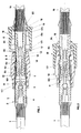
- Fig. 1 is a section of a first embodiment of the invention, represented when the female cap is not yet locked on the male cap;
- Fig. 2 shows the pin coupling of Fig. 1 when the female cap is locked on the male cap;
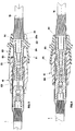
- Fig. 3 shows a cross-section of a different embodiment of the pin coupling of the Figs. 1 and 2;
- Fig. 4 shows the pin coupling of Fig. 3 when the female cap is locked on the male cap;
- Fig. 5 shows a cross-section of another different embodiment of the pin coupling according to the invention.
- With reference to the mentioned Figs., it can be observed that the co-axial cable, indicated with 1, is connected to a male connector, indicated as a whole with 2, which presents a
central conductor 3 receiving the signal and which is separated from theoutside metal screen 5 through aninsulating material 4. Said outsidemetal screen 5 extends until the rim indicated with 5a and presents also andelastic element 5b suited to ensure the contact with the corresponding metallic screening of the female connector, to which is connected and which is indicated as a whole with 6. Said female connector, connected to theco-axial cable 15, presents afemale contact 7 within which themale contact 3 of themale connector 2 is then coupled. Such afemale contact 7 is separated from the outside metal screen, indicated as a whole with 9, through aninsulating material 8. Such a metal screen extends to theterminal part 9a projecting toward the coupling and it presents twoannular projecting parts 9b and 9c, placed at such a distance that, as it will be observed hereinafter, they cooperate with the holding means belonging to themale cap 10 and thefemale cap 16 respectively of the pin coupling according to the invention. - The male cap, indicated as a whole with 10, is inserted in the
female connector 2. Such a male cap, made of plastic material, locks itself on the connector lodging the same, through a projectingpart 11 being present on the inner surface of said male cap, since such a projectingpart 11 positions itself on acorresponding groove 111 obtained by performing a shrinking of the outside diameter of themetal screen 5. The outer profile of the terminal part of themale cap 10 has the shape of a truncated-cone, as indicated in 12. Internally, in correspondence of said truncated-conic shape part 12, the male cap presents a flared connecting surface, indicated with 13, which precedes anannular recess 14 on which the projectingpart 9b, belonging to theoutside metal screen 9 of thefemale connector 6, positions itself when the coupling of themale cap 10 on theconnector 12 is performed. This happens becausepart 12 in the shape of a truncated-cone of the male cap has such a shape and thickness that the characteristics of elasticity of its plastic material are enhanced. Preferably, such apart 12 in the shape of a truncated-cone consists of sectors obtained through two or more longitudinal cuts. Moreover, near the projectingpart 11 there is a slightannular relief 101 which ensures the water tightness between themale cap 10 and themale connector 2. - The female cap, indicated as a whole with 16, which is also preferably made of plastic material, presents an
opening 17 with a wider diameter as compared to the opposite part which ends with acylindrical element 18. The profile of said female cap is initially cylindrical and then it continues with aconic section 17a which will then couple with thecorresponding conic section 12 of themale cap 10. Theconic section 17a is followed by acylindrical section 17b which ends with anothercylindrical element 18 having a smaller diameter. Saidcylindrical element 18 presents, in correspondence with the rims, two internalannular projections metal screen 9 of thefemale connector 6. - The electric contact between the two male and
female connectors male cap 10 and thefemale cap 16, occur by pushing thecable 15 against theco-axial cable 1, after theconnector 2 and thecap 10 have been assembled oncable 1, and after theconnector 6 and thefemale cap 16 have been assembled oncable 15. By pushing thefemale connector 6 against themale connector 2, themale cap 10 couples with thefemale connector 9 through the coupling which is obtained between theannular recess 14 of themale cap 10 and the projectingpart 9b belonging to theconnector 6. If the pushing of thefemale cap 16 against themale cap 10 is carried further, the internalannular projection 19 of thecylindrical element 18 goes past the projecting part 9c so that said projecting part remains inside thecylindrical element 18 between the internalannular projections - In other words, the internal
annular projection 19, having gone beyond the projecting part 9c, keeps thefemale cap 16 locked on themale cap 10. This action is helped by the fact that thecylindrical element 18 is made of plastic material of low thickness and consequently theelement 18 has enough elasticity. - Thus the locking of the pin coupling which consists of the
male cap 10 and thefemale cap 16 has been obtained in the two projectingparts 9b and 9c, both of them belonging to thefemale connector 6. - As an improvement of said locking between the male cap and the female cap, it can be observed that the internal
annular projection 20 has an internal diameter such as to ensure the water sealing between thefemale cap 16 and thefemale connector 6. Another slightannular relief 171 on the female cap or on the male cap, obtains the water sealing between themale cap 10 and thefemale cap 6. - From what has been described it becomes apparent that the locking of the pin coupling occurs because of the simple sliding of the
female cap 16 on thecap 10. - According to a different embodiment of the female cap, now indicated as a whole with 20 in Fig. 3, such a female cap, on the side that couples with the
male cap 10, presents an opening with aprofile 21, having an essentially truncated-conic shape, with a wider diameter on the coupling side. - From the opposite side, said female cap presents an essentially cylindrical section, indicated with 22, presenting a
flared rim 23 ending with an undercut 23a. On the opposite side of said enlarged opening, thecylindrical section 22 presents an annular tailpiece with aconic shape profile 24, whose smaller diameter contrasts with the metallic surface ofscreen 9 belonging to thefemale connector 6. - Such an
annular tailpiece 24 contrasting with thesurface 9, realizes the seal between said cap and said metallic surface. As a completion of the seal, it can be observed that in the first section of the opening of theinternal surface 20 there is also a slightannular relief 25 which ensures the seal between thefemale cap 20 and the outer surface of themale cap 10. - Before the
female cap 20 locks itself on themale cap 10, the projecting part 9c of thefemale connector 6 is comprised between theflared rim 23a and the annular tailpiece with aconic shape profile 24. - When the
female cap 20 is locked on themale cap 10, the projecting part 9c goes past the undercut 23a and positions itself on theflared rim 23. - The passage of the projecting part 9c from the position illustrated in Fig. 3 to the position in Fig. 4 is made possible by the elasticity of the plastic material which is preferably increased with the help of longitudinal cuts which divide the
section 22 of the female cap into sectors. - Fig. 5 represents yet another embodiment of the invention concerning a different type of seal obtained through an OR sealing ring which guarantees the waterproof sealing by means of an OR ring inserted between the two metal screens of the two male and
female connectors - In order to obtain this according to the embodiment illustrated in Fig. 5, on the inner rim of the
metal screen 5 of themale connector 2, a lodging, indicated with 26, for the accommodation of the OR ring is obtained, wherein said lodging is defined by the shrinking 51 of the inner diameter of themetal screen 5 on one side and on the bent section 52 ofrim 5a of said metal screen on the other side. - The lodging for the OR ring can also be obtained with solutions differing from the one represented in Fig. 5, provided that said OR ring is lodged between the outer metal screens of the two male and female connectors.
- With regard to the pin coupling, the same can be obtained both by the
male cap 10 in combination with thefemale cap 20, as can be observed in Fig. 5, and by themale cap 10 in combination with thefemale cap 16, represented in the Figs. 1 and 2.
Claims (11)
- A pin coupling for locking the connection between a male connector (2) and a female connector (6) connecting co-axial cables (1, 15), comprising:- a male cap (10) holding in its inside the male or female connector (2, 6) of a co-axial cable, whose plug or socket, (3, 7) respectively, carries a high-frequence electrical signal;- a female cap (16, 20) within which the female or male connector (6, 2) of a second co-axial cable (15) to be connected to the first one (1) is inserted, the socket or plug of said cable connecting with the plug or socket, respectively, of said male or female connector, characterized in that said male cap (10) and said female cap (16, 20) lock in the closed position of their connection through the snapping action of holding means belonging to each cap, and co-operating with two annular projecting parts (9b, 9c) being present on the outer metal screen belonging to the female or male connector (6, 2) lodging inside the female cap (16, 20).
- A pin coupling according to claim 1, characterized in that the male cap (10) locks on the connector (2) which lodges it through the coupling of a projecting part (11) found on the inner surface of said male cap (10), said projecting part positioning itself into a corresponding annular recess (111) which is present on the outer surface (5) of said male connector, through an axial relative movement between said cap (10) and said connector (2).
- A pin coupling according to any of the previous claims, characterized in that the terminal part (12) of the male cap (2) has a profile in the shape of a truncated-cone and presents a flared connecting surface (13) between the rim of the hole and the annular recess (14), said terminal part being elastic enough to receive in its annular recess (14) the annular projecting part (9b) belonging to the female or male connector (6, 2).
- A pin coupling according to claim 1, characterized in that the female cap (16) presents a section of its inner surface in the shape of a truncated-cone profile (17a), such to match a corresponding connecting conic profile (12) being present on the outer surface of the male cap.
- A pin coupling according to any of the previous claims, characterized in that the female cap (16), on the side which matches the male cap (10), presents an opening (17) having a wider diameter as compared to the opposite side which ends with an elastic cylindrical element (18) having in correspondence with each of the two rims, an annular inner projection (19, 20) and such a diameter as to slidingly receive the projecting part (9c) of the metal screen (9) belonging to the connector inserted in said female cap, the portion of said cylindrical element (18) being comprised between the two annular projections (19, 20), lodging one of said annular projection parts (9c) when said female cap (16) locks on the male cap (10).
- A pin coupling according to claim 5, characterized in that one the annular inner projections (20) of the cylindrical element (18) belonging to the female cap (16), has a diameter such as to obtain the waterproof sealing in relation to the metal surface of the screen belonging to the connector inserted in the same.
- A pin coupling according to claim 5 or 6, characterized in that the female cap (16), in correspondence with the side presenting the opening with a wider diameter, presents an annular projecting part (171) suited to obtain the waterproof sealing on the outer surface of the male cap.
- A pin coupling according to any of the claims from 1 to 4, characterized in that the female cap (20) presents, on the side matching the male cap, an opening with a profile (21) presenting an essentially truncated-conic shape with a wider diameter on the coupling side, and on the opposite side, it presents an essentially cylindrical section (22) with a flared opening (23) within which one of the two annular projecting parts (9c) lodges, said projecting parts being found on the metal screen belonging to the connector inserted in said female cap, before the male cap and the female cap are locked into one another, said cylindrical section presenting, on the opposite side of the flared opening (23), an annular tailpiece with a conic profile (24) contrasting with the metal surface (9) of the screen belonging to the connector (6) inserted in said female cap (20), such as to obtain the waterproof sealing between said female cap and said metal surface.
- A pin coupling according to claim 8, characterized in that the female cap (20) presents, in correspondence with the side of the opening with a wider diameter, an annular projecting part (25) suited to obtain the waterproof sealing on the outer surface of the male cap (10).
- A pin coupling according to any of the previous claims, characterized in that between the male connector (2) and the female connector (6) an OR sealing ring (26)is inserted to prevent the water from entering.
- A pin coupling according to claim 10, characterized in that the connector (2), which lodges in its interior the other connector (6) matching the same, presents on the inner rim of the metal screen (5) a lodging for an OR sealing ring (52), said lodging being defined by a shrinking (51) of the inner diameter of the metal screen (5) on one side, and by the bent edge (52) of the rim of said metal screen on the other side, the OR ring (26) ensuring the waterproof sealing protection of the electric contact realized by junction of the two contacts.
Applications Claiming Priority (2)
| Application Number | Priority Date | Filing Date | Title |
|---|---|---|---|
| ITVI930197 | 1993-12-13 | ||
| ITVI930197A IT1270760B (en) | 1993-12-13 | 1993-12-13 | PLUG CONNECTION FOR LOCKING THE CONNECTION BETWEEN A MALE CONNECTOR AND A FEMALE CONNECTOR IN A COAXIAL CABLE |
Publications (2)
| Publication Number | Publication Date |
|---|---|
| EP0657967A1 true EP0657967A1 (en) | 1995-06-14 |
| EP0657967B1 EP0657967B1 (en) | 2000-04-05 |
Family
ID=11425376
Family Applications (1)
| Application Number | Title | Priority Date | Filing Date |
|---|---|---|---|
| EP94119310A Expired - Lifetime EP0657967B1 (en) | 1993-12-13 | 1994-12-07 | Pin coupling for locking the connection between a male connector and a female connector of a co-axial cable |
Country Status (3)
| Country | Link |
|---|---|
| EP (1) | EP0657967B1 (en) |
| DE (1) | DE69423855D1 (en) |
| IT (1) | IT1270760B (en) |
Cited By (3)
| Publication number | Priority date | Publication date | Assignee | Title |
|---|---|---|---|---|
| EP1178210A3 (en) * | 2000-07-31 | 2003-06-04 | Kabushiki Kaisha Toyota Jidoshokki | External control variable displacement compressor |
| WO2009074263A1 (en) * | 2007-12-12 | 2009-06-18 | Rosenberger Hochfrequenztechnik Gmbh & Co. Kg | Coaxial plug connector |
| DE10121675B4 (en) * | 2000-05-09 | 2013-12-24 | Escha Bauelemente Gmbh | Electrical plug connection |
Citations (2)
| Publication number | Priority date | Publication date | Assignee | Title |
|---|---|---|---|---|
| EP0450988A1 (en) * | 1990-03-30 | 1991-10-09 | Mecaniplast | Connector for coaxial cable |
| DE4015092A1 (en) * | 1990-05-11 | 1991-11-14 | Hirschmann Richard Gmbh Co | Vibration-resistant coaxial connector - has interlocking plastics material shrouds engaging outer collar with inner groove to seal |
-
1993
- 1993-12-13 IT ITVI930197A patent/IT1270760B/en active IP Right Grant
-
1994
- 1994-12-07 DE DE69423855T patent/DE69423855D1/en not_active Expired - Lifetime
- 1994-12-07 EP EP94119310A patent/EP0657967B1/en not_active Expired - Lifetime
Patent Citations (2)
| Publication number | Priority date | Publication date | Assignee | Title |
|---|---|---|---|---|
| EP0450988A1 (en) * | 1990-03-30 | 1991-10-09 | Mecaniplast | Connector for coaxial cable |
| DE4015092A1 (en) * | 1990-05-11 | 1991-11-14 | Hirschmann Richard Gmbh Co | Vibration-resistant coaxial connector - has interlocking plastics material shrouds engaging outer collar with inner groove to seal |
Cited By (5)
| Publication number | Priority date | Publication date | Assignee | Title |
|---|---|---|---|---|
| DE10121675B4 (en) * | 2000-05-09 | 2013-12-24 | Escha Bauelemente Gmbh | Electrical plug connection |
| EP1178210A3 (en) * | 2000-07-31 | 2003-06-04 | Kabushiki Kaisha Toyota Jidoshokki | External control variable displacement compressor |
| WO2009074263A1 (en) * | 2007-12-12 | 2009-06-18 | Rosenberger Hochfrequenztechnik Gmbh & Co. Kg | Coaxial plug connector |
| US8043117B2 (en) | 2007-12-12 | 2011-10-25 | Rosenberger Hochfrequenztechnik Gmbh & Co. Kg | Coaxial plug connector |
| CN101884142B (en) * | 2007-12-12 | 2013-01-23 | 罗森伯格高频技术有限及两合公司 | Coaxial plug connector |
Also Published As
| Publication number | Publication date |
|---|---|
| DE69423855D1 (en) | 2000-05-11 |
| ITVI930197A0 (en) | 1993-12-13 |
| IT1270760B (en) | 1997-05-07 |
| EP0657967B1 (en) | 2000-04-05 |
| ITVI930197A1 (en) | 1995-06-13 |
Similar Documents
| Publication | Publication Date | Title |
|---|---|---|
| CA2595111C (en) | Contact element for shielded connectors | |
| KR101910283B1 (en) | Coaxial connector assembly | |
| JP5105465B2 (en) | Electrical connector assembly | |
| US4255007A (en) | Multi-terminal rotary connector | |
| US7147513B2 (en) | Shielded connector with insert molded shielding shell and resin cover | |
| US7980894B1 (en) | Coaxial connector with a cable receptor with an outer contact | |
| US5087213A (en) | Lamp socket | |
| US9837761B1 (en) | Electrical cable connector with rotatable housing | |
| US9124016B2 (en) | Connector with covering wall | |
| US10840646B2 (en) | Anti-misplug coaxial connector assembly | |
| US4687446A (en) | Segmented construction for electrical connector assembly | |
| US5913694A (en) | Connector assembly | |
| US6860760B2 (en) | Connector | |
| WO1988004840A1 (en) | Low profile press fit connector | |
| US5316499A (en) | Coaxial connector with rotatable mounting flange | |
| JP4729307B2 (en) | Circuit board connector having an integral dielectric cover | |
| US11417969B2 (en) | Body clamp connector | |
| JP2001035565A (en) | Electrical connector for coaxial cable | |
| JPH0722107A (en) | Shielded wire connector structure | |
| US4180301A (en) | Coaxial cable connector | |
| US3800267A (en) | Lamp socket | |
| US3456232A (en) | Self-sealing connector | |
| US4936798A (en) | Electrical connector | |
| EP0270270B1 (en) | Electrical connector housing assembly | |
| US4192566A (en) | Antenna lead splice |
Legal Events
| Date | Code | Title | Description |
|---|---|---|---|
| PUAI | Public reference made under article 153(3) epc to a published international application that has entered the european phase |
Free format text: ORIGINAL CODE: 0009012 |
|
| AK | Designated contracting states |
Kind code of ref document: A1 Designated state(s): DE ES FR GB |
|
| 17P | Request for examination filed |
Effective date: 19951214 |
|
| 17Q | First examination report despatched |
Effective date: 19980421 |
|
| GRAG | Despatch of communication of intention to grant |
Free format text: ORIGINAL CODE: EPIDOS AGRA |
|
| GRAG | Despatch of communication of intention to grant |
Free format text: ORIGINAL CODE: EPIDOS AGRA |
|
| GRAH | Despatch of communication of intention to grant a patent |
Free format text: ORIGINAL CODE: EPIDOS IGRA |
|
| GRAH | Despatch of communication of intention to grant a patent |
Free format text: ORIGINAL CODE: EPIDOS IGRA |
|
| GRAA | (expected) grant |
Free format text: ORIGINAL CODE: 0009210 |
|
| AK | Designated contracting states |
Kind code of ref document: B1 Designated state(s): DE ES FR GB |
|
| PG25 | Lapsed in a contracting state [announced via postgrant information from national office to epo] |
Ref country code: FR Free format text: LAPSE BECAUSE OF FAILURE TO SUBMIT A TRANSLATION OF THE DESCRIPTION OR TO PAY THE FEE WITHIN THE PRESCRIBED TIME-LIMIT Effective date: 20000405 Ref country code: ES Free format text: THE PATENT HAS BEEN ANNULLED BY A DECISION OF A NATIONAL AUTHORITY Effective date: 20000405 |
|
| REF | Corresponds to: |
Ref document number: 69423855 Country of ref document: DE Date of ref document: 20000511 |
|
| PG25 | Lapsed in a contracting state [announced via postgrant information from national office to epo] |
Ref country code: DE Free format text: LAPSE BECAUSE OF FAILURE TO SUBMIT A TRANSLATION OF THE DESCRIPTION OR TO PAY THE FEE WITHIN THE PRESCRIBED TIME-LIMIT Effective date: 20000706 |
|
| EN | Fr: translation not filed | ||
| PG25 | Lapsed in a contracting state [announced via postgrant information from national office to epo] |
Ref country code: GB Free format text: LAPSE BECAUSE OF NON-PAYMENT OF DUE FEES Effective date: 20001207 |
|
| PLBE | No opposition filed within time limit |
Free format text: ORIGINAL CODE: 0009261 |
|
| STAA | Information on the status of an ep patent application or granted ep patent |
Free format text: STATUS: NO OPPOSITION FILED WITHIN TIME LIMIT |
|
| 26N | No opposition filed | ||
| GBPC | Gb: european patent ceased through non-payment of renewal fee |
Effective date: 20001207 |