EP0658478B1 - Pneumatic de-icer having improved aerodynamic characteristics - Google Patents
Pneumatic de-icer having improved aerodynamic characteristics Download PDFInfo
- Publication number
- EP0658478B1 EP0658478B1 EP94111812A EP94111812A EP0658478B1 EP 0658478 B1 EP0658478 B1 EP 0658478B1 EP 94111812 A EP94111812 A EP 94111812A EP 94111812 A EP94111812 A EP 94111812A EP 0658478 B1 EP0658478 B1 EP 0658478B1
- Authority
- EP
- European Patent Office
- Prior art keywords
- carcass
- inflatable
- inflatable passages
- icer
- passages
- Prior art date
- Legal status (The legal status is an assumption and is not a legal conclusion. Google has not performed a legal analysis and makes no representation as to the accuracy of the status listed.)
- Expired - Lifetime
Links
Images


Classifications
-
- B—PERFORMING OPERATIONS; TRANSPORTING
- B64—AIRCRAFT; AVIATION; COSMONAUTICS
- B64D—EQUIPMENT FOR FITTING IN OR TO AIRCRAFT; FLIGHT SUITS; PARACHUTES; ARRANGEMENT OR MOUNTING OF POWER PLANTS OR PROPULSION TRANSMISSIONS IN AIRCRAFT
- B64D15/00—De-icing or preventing icing on exterior surfaces of aircraft
- B64D15/16—De-icing or preventing icing on exterior surfaces of aircraft by mechanical means, e.g. pulsating mats or shoes attached to, or built into, surface
- B64D15/166—De-icing or preventing icing on exterior surfaces of aircraft by mechanical means, e.g. pulsating mats or shoes attached to, or built into, surface using pneumatic boots
Definitions
- This invention relates to aircraft de-icers and more particularly to an improved inflatable de-icer or boot adapted for attachment to the airfoil of an aircraft for use in retarding the accumulation of ice or to remove or break up ice accumulation.
- Aircraft inflatable de-icers, pads or boots are made of resilient material such as rubber and attached to the leading edge of an airfoil and extend rearwardly therefrom.
- the de-icer has a series of inflatable passages or tubes which are distended by inflation pressure to break up ice accumulation which tends to form on the surface of the de-icer.
- the passages or tubes are deflated by releasing the pressure medium and drawing a vacuum thereon.
- the normal sequence of operation is a continuous cycling of the inflation and deflation process.
- An example of a de-icer in the art is presented in United States Patent 4,779,823 PNEUMATIC DE-ICER, Ely et al.
- This de-icer incorporates a multitude of spanwise inflatable passages on either side of a leading edge that run parallel to the leading edge. A non-inflatable region overlies the leading edge. The inflatable passages to one side of the leading edge are cycled alternatively with the inflatable passages to the other side of the leading edge which generates a clamshell action that more effectively removes ice by cracking the ice accumulation along the leading edge.
- Another de-icer in the art is presented in United States Patent 4,561,613 DEICER FOR AIRCRAFT, Shoesnd, Jr. This de-icer incorporates a multitude of chordwise inflatable passages that are parallel to the airstream that impinges upon the de-icer and passes around the airfoil.
- chordwise tubes are less disruptive to the surrounding airstream that passes over the airfoil than spanwise tubes during inflation of the de-icer.
- spanwise tubes remove ice much better than chordwise tubes on many airfoil geometries, particularly those geometries that have small leading edge radiuses.
- Modern aircraft have flight surfaces that are sensitive to perturbations in the airstream that passes over the airfoil. Changes in an airfoil shape during inflation of a de-icer can cause undesirable changes in the aerodynamic characteristics of the airfoil. Therefore, a de-icer is desired that effectively removes ice without undesirably effecting aerodynamic characteristics.
- a de-icer comprising an elastomeric inner layer having an inner layer fabric; an elastomeric outer layer having a stretchable outer layer fabric overlying and attached to the inner layer, the outer layer fabric that overlies the first side portion having a first primary stretch direction, the outer layer fabric that overlies the second side portion having a second primary stretch direction, the second primary stretch direction being misaligned with the first primary stretch direction, the first primary stretch direction meeting the second primary stretch direction about parallel and proximate to the stagnation line, the inner layer being sewn to the outer layer in a predetermined pattern that forms a multitude of inflatable passages between the inner and outer layers that overlay the first and second side portions proximate to the leading edge; and, inflation means for communicating a pressurized fluid to the inflatable passages.
- the de-icer can further comprise a pair of spaced margins to either side of the stagnation line and parallel thereto, the area between the spaced margins defining a non-inflatable region, wherein the inflatable passages that overlay the first side portion and the inflatable passages that overlay the second side portion abut the non-inflatable region along the spaced margins.
- a method of building a de-icer comprising the steps of forming a first carcass by sewing two first carcass fabric layers together in a predetermined pattern that forms inflatable passages between the first carcass layers, the first carcass having a first primary stretch direction, a first carcass perimeter including a first edge, a first carcass inner side and an opposing first carcass outer side; forming a second carcass by sewing two second carcass fabric layers together in a predetermined pattern that forms inflatable passages between the two second carcass fabric layers, the second carcass having a second primary stretch direction, a second carcass perimeter including a second edge, a second carcass inner side and an opposing second carcass outer side; abutting the first carcass and the second carcass along the first and second edges, the first primary stretch direction being substantially misaligned with the second primary stretch direction; applying and bonding an attachment layer comprising elastomeric material to the first and second inner carcass sides, the inner layer having a perimeter that extends beyond the first and second carcass perimeters; and applying
- the method can further comprise the step of forming a non-inflatable region having a width that extends into the first and second carcasses on either side of the first and second edges by bonding a thin elastomeric strip between the two fabric layers of the first and second carcasses along the first and second edges, the thin elastomeric strip having a total width approximately corresponding to the non-inflatable region width.
- an aircraft tail section 2 is presented in plan view.
- Aircraft tail section 2 comprises a vertical tailplane 3 and two horizontal tailplanes 4 and 7.
- a de-icer 20 according to the invention is shown attached to the forward portion of tailplane 4. Though shown attached to a tailplane, de-icer 20 can also be adapted to another aircraft flight surface such as a wing.
- An airstream 8 impinges upon a leading edge 18 and splits into first airstream 10 and a second airstream 12 that pass over the tailplane 4.
- the leading edge 18 of tailplane 4 forms a sweep angle 6.
- Airstream 10 is shown as a dashed line since it passes over the opposite side of tailplane 4 out of view.
- the tailplane 4 is generally shaped as an airfoil 5 and has a first side portion 14 and a second side portion 16 that converge into a convex leading edge 18.
- a stagnation line 17 forms near leading edge 18 where airstream 8 splits into first and second airstreams 10 and 12.
- the stagnation line 17 is about parallel to the leading edge 17 and is normally shifted a short distance to one side (however, the stagnation line could directly overlay the leading edge 18 with some airfoil geometries).
- the airfoil 5 is shown inverted such that a downward force is generated on the tailplane 4 while the aircraft is in flight.
- Second airstream 12 passes over the second side portion 16.
- De-icer 20 is shown mounted on an existing airfoil 5 such that the de-icer 20 slightly alters the intended shape of airfoil 5. This can be avoided by appropriately recessing the airfoil 5 such that the exposed surface of de-icer 20 conforms with the intended airfoil shape.
- De-icer 20 is shown in plan view in Figure 3.
- airstream 10 forms an angle 11 with a line perpendicular to leading edge 18
- airstream 12 forms an angle 13 with a line perpendicular to the leading edge 18, angles 11 and 13 approximating the sweep angle 6 (Figure 1).
- Stagnation line 17 is shown shifted a short distance from leading edge 18.
- a multitude of inflatable passages 23 overlay the first and second side portions 14 and 16 proximate to the leading edge 18 when de-icer 20 is attached the tailplane 4.
- Some inflatable passages 22 overlay the first side portion 14 ( Figure 2) when the de-icer 20 is installed. Substantially all of the inflatable passages that overlay the first side portion 22 are about parallel to the leading edge 18.
- inflatable passages 22 could form some small angle with the leading edge 18 which is intended to be within the purview of this invention.
- Some inflatable passages 24 overlay the second side portion 16 ( Figure 2) when the de-icer 20 is installed. Substantially all of the inflatable passages that overlay the second side portion 24 are about parallel to the first airstream 12 (which is parallel to airstream 8).
- the term “about parallel” is used to indicate that inflatable passages 24 could form some small angle with the airstream 12 which is intended to be within the purview of this invention.
- substantially is intended to indicate that nearly all of the inflatable passages conform as described. For example, inflatable passages 24 could extend a short distance past stagnation line 17 over first side portion 14, or inflatable passages 22 could extend a short distance past stagnation line 17 over the second side portion 16.
- Inflatable passages 24 disrupt second airstream 12 less than inflatable passages 22 (parallel to the leading edge) disrupt first airstream 10 when the tubes are inflated.
- inflatable passages that are parallel to the airstream are less disruptive and have much less effect on the intended aerodynamic characteristics of an airfoil while the de-icer is inflated.
- de-icing tests have demonstrated that for many airfoil geometries, particularly those having small leading edge radiuses, inflatable passages parallel to a leading edge are more effective in removing ice than inflatable passages parallel to the airstream.
- inflatable passages that overlay the critical side can be arranged about parallel to the airstream.
- the rest of the inflatable passages can remain parallel to the leading edge.
- the resulting de-icer preserves ice removal capability but should also preserve the intended aerodynamic characteristics of the airfoil during de-icer inflation.
- the inflatable passages that are parallel to the airstream could overlay either side of the airfoil depending on the application.
- the inflatable passages that overlay the other side of the airfoil remain parallel to the leading edge. Which of the two opposing airfoil surfaces is critical depends upon the aerodynamic characteristics of the particular flight surface and its interaction with the entire aircraft.
- De-icer 20 comprises elastomeric inner layer 30 which is attached to elastomeric outer layer 32, and inflatable passages 22 and 24 between the inner and outer layers 30 and 32.
- Inner layer 30 includes inner layer fabric 40 and airfoil attachment layer 42, and an attachment surface 28.
- Outer layer 32 includes outer layer fabric 38, resilient layer 36, erosion layer 34, and airstream surface 26. The airstream surface 26 is spaced from and superposed over the attachment surface 28.
- Attachments 50 join the inner layer 30 to the outer layer 32 in a manner that defines the multitude of inflatable passages 22 and 24.
- Inflation means for communicating a pressurized fluid to inflatable passages 24 comprises a manifold 56 which includes a bleeder strip 58 bounded by two tapered fillets 60 having a thickness that decreases with distance from the bleeder strip 58.
- Manifold 56 is included within inner layer 30 and extends along de-icer 20 approximately parallel to leading edge 18 beneath inflatable passages 24.
- An air connection opening 64 is formed through inner layer 30 and an air connection 62 is bonded to the attachment surface 28 over the opening 64. Openings 66 are formed in inner layer fabric 40 at spaced intervals along the de-icer 20.
- a pressurized fluid such as air
- the pressurized fluid passes into the bleeder strip 58 which distributes the pressurized fluid along the length of de-icer 20, the pressurized fluid then passes into the inflatable passages through the openings 66 and inflates the inflatable passages 24.
- Materials for forming manifolds are well known in the pneumatic de-icer art. As will be discussed, the manifold is optional with a sewn-type de-icer. The perimeter of the de-icer is preferably tapered as shown.
- de-icer 20 comprises elastomeric inner layer 30 and elastomeric outer layer 32.
- Inflatable passages 22 lie between the inner and outer layers 30 and 32.
- Inner layer 30 includes attachment layer 42 and inner layer fabric 40.
- Outer layer 32 includes outer layer fabric 38, elastomeric resilient layer 36 and elastomeric erosion layer 34.
- Inflation means for communicating a pressurized fluid to the inflatable passages 22 comprises inflation manifold 78 which is very similar to inflation manifold 56.
- Manifold 78 includes a bleeder strip 68 bounded by two tapered fillets 70 having a thickness that decreases with distance from the bleeder strip 68.
- Manifold 78 is included within inner layer 30 and extends along de-icer 20 beginning close to the leading edge 18 and extending aft approximately perpendicular to leading edge 18 beneath inflatable passages 22.
- An air connection opening 74 is formed through inner layer 30 and an air connection 72 is bonded to the attachment surface 28 over the opening 74.
- Openings 76 are formed in inner layer fabric 40 at spaced intervals along the de-icer 20.
- a pressurized fluid such as air
- the pressurized fluid passes into the bleeder strip 68 which distributes the pressurized fluid along the width of de-icer 20, the pressurized fluid then passes into the inflatable passages through the openings 76 and inflates the inflatable passages 22.
- the manifold is optional with a sewn type de-icer.
- de-icer 20 comprises inner layer 30 which is attached to outer layer 32.
- Inflatable passages 24 lie between inner and outer layers 30 and 32.
- Attachments 50 join the inner layer 30 to the outer layer 32 in a manner that defines the inflatable passages 24.
- Inner layer 30 includes attachment layer 42 and inner layer fabric 40.
- Outer layer 32 includes outer layer fabric 38, elastomeric resilient layer 36 and elastomeric erosion layer 34.
- Figure 8 represents a sewn-type de-icer which is preferred.
- Inner layer fabric 40 and stretchable outer layer fabric 38 are coated on one surface with elastomeric material. The uncoated surfaces are placed immediately adjacent each other and the two layers are sewn together in a predetermined pattern that defines the multitude of inflatable passages 23.
- the facing fabric surfaces can be napped to facilitate flow of pressurized fluid (such as air) to the inflatable passages 23.
- Attachments 52 are parallel rows of stitching.
- a resilient layer 36 is bonded to outer layer fabric 38 and erosion layer 34 is bonded to resilient layer 36.
- Inner layer fabric 40 is bonded to attachment layer 42.
- Outer layer fabric 38 is preferably a tricot woven polyamide (nylon) fabric coated on one surface with natural rubber.
- Inner layer fabric 40 is preferably a square woven polyamide (nylon) fabric coated on one surface with natural rubber. The two layers are preferably sewn together with polyamide (nylon) thread.
- Attachment layer 42 is preferably a chloroprene rubber.
- Erosion layer 34 is preferably either choloroprene rubber or polyurethane elastomer, either material being suitable as an erosion surface, with polyurethane elastomer generally having better resistance to rain and sand erosion.
- Cement layers (not shown) are provided between the various layers (except between the inner and outer fabric layers 38 and 40) that bond the de-icer into a cohesive unit.
- Suitable elastomer compounds, fabrics, bond cements, and tie-in cements are well known in the pneumatic de-icer art.
- the de-icer is preferably cured under heat and pressure in an autoclave.
- a nominal thickness of the de-icer between the airstream surface 26 and attachment surface 28 is about 1,9 - 2,3 mm (.075 to .090 inch) after cure.
- openings 66 and 76 Figures 5 and 6) can be spaced along the manifold every third or fourth inflatable passage (or as required by the particular application).
- manifolds 56 and 78 may not be necessary, in which case, the inflation means would only require openings 64 and 74 and air connections 62 or 72.
- a preferred embodiment of the invention is presented in Figure 4.
- Preferred de-icer 100 is very similar to de-icer 20.
- a sectional view parallel to leading edge 18 through de-icer 100 over inflatable passages 22 is identical to the corresponding sectional view for de-icer 20 presented in Figure 6.
- a sectional view parallel to leading edge 18 through de-icer 100 over inflatable passages 24 is identical to the corresponding sectional view for de-icer 20 presented in Figure 7.
- two alternatives for forming inflatable passages 23 are presented in Figures 8 and 9, with the sewn embodiment of Figure 8 being preferred.
- de-icer 100 includes two spaced margins 104 and 106 on either side of stagnation line 17 defining a non-inflatable region 102.
- Inflatable passages 24 abut the non-inflatable region 102 along spaced margin 104, and inflatable passages 22 abut the non-inflatable region 102 along the other spaced margin 106.
- the non-inflatable region 102 improves the de-icing capability of de-icer 100 by inducing a clamshell action that splits an ice cap along the stagnation line 17 upon inflation of the inflatable passages 23.
- the structure and function of a "clamshell" de-icer is fully described in United States Patent 4,779,823 PNEUMATIC DEICER, Ely et al., issued October 25, 1988.
- the width of non-inflatable region 102 is preferably about 1,27 cm (.5 inch).
- FIG. 9 A sectional view across the full de-icer 100 perpendicular to leading edge 18 is presented in Figure 9.
- An example for forming inflatable passages 23 is presented in Figure 8 which represent a sewn-type constructions.
- the boundaries of non-inflatable region 102 are defined by spaced margins 104 and 106.
- Dead strip 108 separates inflatable passages 24 from inflatable passages 22 and is not inflatable.
- Two alternatives for forming non-inflatable region 102 are presented in Figures 10 and 11.
- a preferred embodiment is presented in Figure 10 for use in the sewn-type de-icer construction of Figure 8.
- Inner layer fabric 40 and outer layer fabric 38 are immediately adjacent and sewn together at attachment points 52, as previously discussed in relation to Figure 8.
- the inner layer fabric 40 and outer layer fabric 38 that overlay the first side portion 14 form a first carcass that is sewn together in a predetermined pattern of inflatable passages 22.
- the inner layer fabric 40 and outer layer fabric 38 that overlay the second side portion 16 form a second carcass that is sewn together in a predetermined pattern of inflatable passages 24.
- the first and second carcasses are separate and distinct and each have a coextensive edge 123 and 125 along which each abuts the other in the non-inflatable region 102.
- the sewn attachments 52 immediately adjacent the non-inflatable zone 102 correspond to the locations of the spaced margins 104 and 106.
- a narrow strip of elastomeric material 118 lies between the inner and outer layer fabrics 40 and 38 and bonds the two fabric layers together.
- the narrow strip 118 has a width that approximates the distance between spaced margins 104 and 106, and is preferably formed from natural rubber. As discussed previously in relation to Figure 8, manifold 56 is optional.
- a maximum tube inflation height 134 In order to obtain the most effective de-icing action, a maximum tube inflation height 134 must be achieved as depicted in Figure 11. This inflation height is ideally between about 0,64 - 0,89 cm (.25 to .35 inch) at room temperature.
- Tricot fabric which is preferably used for the outer layer stretchable fabric, has a primary stretch direction in which the material stretches a maximum amount. If the primary stretch direction is aligned with the inflatable passage width, inflation height 134 is mostly a function of three variables: inflation pressure, inflatable passage width 138, and the specific materials used to construct the deicer. Inflatable passage width 138 ranges from about 1,9 - 4,4 cm (.75 inch to 1.75 inch) as required by the three variables.
- the primary stretch direction 130 is usually across the fabric width perpendicular to the direction 128 from which the fabric comes off the roll. Ideally, the primary stretch direction is across the width 138 of the inflatable passage. This optimum arrangement is not difficult to achieve with inflatable passages that are about parallel the leading edge, for example inflatable passages 22 of Figures 3 and 4. Inflatable passages 22 of nearly any length could be formed from stretchable fabric 132 which would result in a first primary stretch direction 37 as shown in Figures 3 and 4.
- the predetermined tube pattern of inflatable passages 24 can be oriented at an angle relative to the direction 128 the fabric comes off the roll as shown in Figure 12. Since de-icers are usually much longer than the width of fabric 132, the tube pattern is optimally placed on as much of an angle as possible.
- the angle 13 ( Figures 3 and 4) can be advantageously used to more closely align the stretch direction 130 across the widths 138 of the inflatable passages.
- Second primary stretch direction 39 formed an angle of about 13 (thirteen) degrees with the inflatable passage width which was compensated by increasing the tube width to about 3,2 cm (1.25 inch). The increase in width increased the inflation height to the desired level.
- the first primary stretch direction 37 is misaligned with the second primary stretch direction 39 in de-icers 20 or 100 of Figures 3 and 4.
- the first primary stretch direction meets the second primary stretch direction proximate and about parallel to the stagnation line 17.
- the angle of misalignment is usually substantial since the airstream 8, with which inflatable passages 24 are aligned, is usually nearly perpendicular to the leading edge 18, with which inflatable passages 22 are aligned.
- inflatable passages 22 and 24 must be formed as separate carcasses with different primary stretch directions.
- a sewn type de-icer may be constructed according to the following method.
- a first carcass 25 ( Figures 3 and 4) is formed by sewing two first carcass fabric layers (inner layer 40 and outer stretchable layer 38 as shown in Figure 8) together in a predetermined pattern that forms inflatable passages 23 between the two first carcass fabric layers.
- the predetermined pattern comprises elongate inflatable passages 22 in side-by-side relationship in a first common direction about parallel to leading edge 18.
- the first carcass 25 has a first primary stretch direction which is aligned as closely as possible with the width of the inflatable passages 22.
- the first carcass 25 has a first carcass perimeter 124 including a first edge 123, a first carcass inner side (corresponding to the inner side 41 of inner fabric layer 40 as shown in Figure 8) and an opposing first carcass outer side (corresponding to the outer side 39 of outer fabric layer 38 as shown in Figure 8).
- a second carcass 27 ( Figures 3 and 4) is formed by sewing two second carcass fabric layers (inner fabric layer 40 and outer stretchable fabric layer 38 as shown in Figure 8) together in a predetermined pattern that forms inflatable passages 23 between the two second carcass fabric layers. Referring to Figures 3 and 4, the predetermined pattern comprises elongate inflatable passages 24 in side-by-side relationship in a second common direction about parallel to airstream 12.
- the second carcass 27 has a second primary stretch direction 39 which is aligned as closely as possible with the width of the inflatable passages 24.
- the second carcass 27 has a second carcass perimeter 126 including a second edge 125, a second carcass inner side (corresponding to first carcass inner side 41 as shown in Figure 8) and an opposing second carcass outer side (corresponding to second carcass inner side 39 as shown in Figure 8).
- the first carcass 25 and second carcass 27 are then abutted along the first and second edges 123 and 125 which are coextensive.
- the two carcasses abutt about parallel and proximate to stagnation line 17. As discussed previously, the first common direction is misaligned with the second common direction.
- first primary stretch direction 37 is misaligned with the second primary stretch direction 39.
- the attachment layer 42 ( Figure 8) is applied and bonded to the first and second inner carcass sides 41 ( Figure 8).
- the attachment layer 42 has a perimeter 127 that extends beyond the first and second carcass perimeters 124 and 126.
- a surface layer (resilient layer 36 and erosion layer 34 of Figure 8) is applied and bonded to the first and second outer carcass sides 39 ( Figure 8).
- the surface layer has a perimeter 127 that extends beyond the first and second carcass perimeters 124 and 126, as shown in Figures 3 and 4.
- non-inflatable region 102 has a width that extends into the first and second carcasses 25 and 27 on either side of the first and second edges 123 and 125 as depicted in Figure 4.
- the non-inflatable region is formed by inserting and bonding a thin elastomeric strip 118 between the two fabric layers of the first and second carcasses 25 and 27 along the first and second edges 123 and 125 as depicted in Figures 4 and 10.
- Thin elastomeric strip 118 has a total width that approximately corresponds to the non-inflatable region width between spaced margins 104 and 106.
- carcasses 25 and 27 are formed as described above. Erosion layer 34 is applied to a polished stainless steel sheet. Resilient layer 36 is applied over the erosion layer 34. Carcasses 25 and 27 are then abutted along first and second edges 123 and 125 along stagnation line 17 and applied to the resilient layer 36 with the stretchable outer fabric layer immediately adjacent the resilient layer 36. The inner layer fabric 38 is then peeled back along first and second edges 123 and 125 and a elastomeric strip 118 is applied to the stretchable fabric layer 40 in the non-inflatable region 102 using appropriate adhesive. The inner layer fabric 38 is then pushed back down over the elastomeric strip which creates the construction shown in Figure 10.
- manifolds 56 ( Figures 5 and 9) and 78 ( Figure 6) are then applied to the inner layer fabric along with the appropriate openings 64, 66, 74 and 76.
- Attachment layer 42 is then applied over the entire construction.
- Appropriate bond cements and tie-in cements are used in between the various layers as previously discussed.
- a vacuum bag is applied over the construction and sealed to the stainless steel sheet around the perimeter of the de-icer which is subsequently cured under heat and pressure.
- Air connections 62 and 72 are bonded over openings 64 and 74 using an air cure adhesive. Suitable elastomer compounds, fabrics, bond cements, and tie-in cements are well known in the pneumatic de-icer art.
- the de-icer is preferably attached to the airfoil using a solvent based rubber adhesive.
- a very desirable adhesive is 3M 1300L if the attachment surface of the de-icer is chloroprene rubber.
- Methods for attaching de-icers to airfoils are well known in the art.
- all of the inflatable passages 23 can be inflated simultaneously. Inflation can also alternate between inflatable passages that overlay the first side portion 22 and inflatable passages that overlay the second side portion 24. Compressed air is normally used to inflate the de-icer, but other pressurized fluids could be used.
- Equipment for inflating de-icers and controlling inflation cycles is well known in the art.
Landscapes
- Engineering & Computer Science (AREA)
- Mechanical Engineering (AREA)
- Aviation & Aerospace Engineering (AREA)
- Tents Or Canopies (AREA)
- Laminated Bodies (AREA)
- Air Bags (AREA)
Description
- This invention relates to aircraft de-icers and more particularly to an improved inflatable de-icer or boot adapted for attachment to the airfoil of an aircraft for use in retarding the accumulation of ice or to remove or break up ice accumulation.
- Aircraft inflatable de-icers, pads or boots are made of resilient material such as rubber and attached to the leading edge of an airfoil and extend rearwardly therefrom. The de-icer has a series of inflatable passages or tubes which are distended by inflation pressure to break up ice accumulation which tends to form on the surface of the de-icer. The passages or tubes are deflated by releasing the pressure medium and drawing a vacuum thereon. The normal sequence of operation is a continuous cycling of the inflation and deflation process. An example of a de-icer in the art is presented in United States Patent 4,779,823 PNEUMATIC DE-ICER, Ely et al. This de-icer incorporates a multitude of spanwise inflatable passages on either side of a leading edge that run parallel to the leading edge. A non-inflatable region overlies the leading edge. The inflatable passages to one side of the leading edge are cycled alternatively with the inflatable passages to the other side of the leading edge which generates a clamshell action that more effectively removes ice by cracking the ice accumulation along the leading edge. Another de-icer in the art is presented in United States Patent 4,561,613 DEICER FOR AIRCRAFT, Weisend, Jr. This de-icer incorporates a multitude of chordwise inflatable passages that are parallel to the airstream that impinges upon the de-icer and passes around the airfoil. The preambles of
claims 1 and 5 are based on this document. In general, chordwise tubes are less disruptive to the surrounding airstream that passes over the airfoil than spanwise tubes during inflation of the de-icer. Conversely, spanwise tubes remove ice much better than chordwise tubes on many airfoil geometries, particularly those geometries that have small leading edge radiuses. - Modern aircraft have flight surfaces that are sensitive to perturbations in the airstream that passes over the airfoil. Changes in an airfoil shape during inflation of a de-icer can cause undesirable changes in the aerodynamic characteristics of the airfoil. Therefore, a de-icer is desired that effectively removes ice without undesirably effecting aerodynamic characteristics.
- It is an object of the invention to improve a de-icer and a method of building a de-icer with inflatable passages with different orientations.
- This object is solved, according to the invention, with the features of
claim 1 or 5. - According to the invention, a de-icer is provided comprising an elastomeric inner layer having an inner layer fabric; an elastomeric outer layer having a stretchable outer layer fabric overlying and attached to the inner layer, the outer layer fabric that overlies the first side portion having a first primary stretch direction, the outer layer fabric that overlies the second side portion having a second primary stretch direction, the second primary stretch direction being misaligned with the first primary stretch direction, the first primary stretch direction meeting the second primary stretch direction about parallel and proximate to the stagnation line, the inner layer being sewn to the outer layer in a predetermined pattern that forms a multitude of inflatable passages between the inner and outer layers that overlay the first and second side portions proximate to the leading edge; and, inflation means for communicating a pressurized fluid to the inflatable passages.
- The de-icer can further comprise a pair of spaced margins to either side of the stagnation line and parallel thereto, the area between the spaced margins defining a non-inflatable region, wherein the inflatable passages that overlay the first side portion and the inflatable passages that overlay the second side portion abut the non-inflatable region along the spaced margins.
- A method of building a de-icer is provided, comprising the steps of forming a first carcass by sewing two first carcass fabric layers together in a predetermined pattern that forms inflatable passages between the first carcass layers, the first carcass having a first primary stretch direction, a first carcass perimeter including a first edge, a first carcass inner side and an opposing first carcass outer side; forming a second carcass by sewing two second carcass fabric layers together in a predetermined pattern that forms inflatable passages between the two second carcass fabric layers, the second carcass having a second primary stretch direction, a second carcass perimeter including a second edge, a second carcass inner side and an opposing second carcass outer side; abutting the first carcass and the second carcass along the first and second edges, the first primary stretch direction being substantially misaligned with the second primary stretch direction; applying and bonding an attachment layer comprising elastomeric material to the first and second inner carcass sides, the inner layer having a perimeter that extends beyond the first and second carcass perimeters; and applying and bonding a surface layer comprising elastomeric material to the first and second outer carcass sides, the outer layer having a perimeter that extends beyond the first and second carcass perimeters.
- The method can further comprise the step of forming a non-inflatable region having a width that extends into the first and second carcasses on either side of the first and second edges by bonding a thin elastomeric strip between the two fabric layers of the first and second carcasses along the first and second edges, the thin elastomeric strip having a total width approximately corresponding to the non-inflatable region width.
- FIG. 1 is a plan view of an aircraft tail section.
- FIG. 2 is a sectional view of an aircraft tailplane parallel to an airstream that passes around the airfoil.
- FIG. 3 is a plan view of a de-icer according to the invention.
- FIG. 4 is a plan view of a de-icer according to a preferred embodiment of the invention.
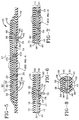
- FIG. 5 is a sectional view across the full de-icer of Figure 3 perpendicular to the leading edge.
- FIG. 6 is a sectional view parallel to leading edge through the de-icer over the inflatable passages that are parallel to the leading edge.
- FIG. 7 is a sectional view parallel to leading edge through the de-icer over inflatable passages that are parallel to the airstream.
- FIG. 8 is an example for forming the inflatable passages.
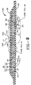
- FIG. 9 is a sectional view across the full de-icer of Figure 4 perpendicular to the leading edge.
- FIG. 10 is a preferred embodiment wherein the inner layer fabric and outer layer fabric are immediately adjacent and sewn together.
- FIG. 11 is a schematic view showing inflatable passage inflation height.
- FIG. 12 is a plan view of inflatable passages laid-out on a stretchable fabric having a primary stretch direction across the fabric width.
-
- Preferred embodiments are presented in Figures 1 through 11, wherein like numbered components in the various views are equivalent. Referring to Figure 1, an
aircraft tail section 2 is presented in plan view.Aircraft tail section 2 comprises avertical tailplane 3 and twohorizontal tailplanes 4 and 7. Ade-icer 20 according to the invention is shown attached to the forward portion oftailplane 4. Though shown attached to a tailplane,de-icer 20 can also be adapted to another aircraft flight surface such as a wing. Anairstream 8 impinges upon a leadingedge 18 and splits intofirst airstream 10 and asecond airstream 12 that pass over thetailplane 4. The leadingedge 18 oftailplane 4 forms asweep angle 6. Airstream 10 is shown as a dashed line since it passes over the opposite side oftailplane 4 out of view. - Referring now to Figure 2, a sectional view of
tailplane 4 parallel to theairstream 8 is presented. Thetailplane 4 is generally shaped as anairfoil 5 and has afirst side portion 14 and asecond side portion 16 that converge into a convex leadingedge 18. Astagnation line 17 forms near leadingedge 18 whereairstream 8 splits into first andsecond airstreams stagnation line 17 is about parallel to the leadingedge 17 and is normally shifted a short distance to one side (however, the stagnation line could directly overlay the leadingedge 18 with some airfoil geometries). Theairfoil 5 is shown inverted such that a downward force is generated on thetailplane 4 while the aircraft is in flight. This arrangement appears on many regional airline type aircraft, but in no way limits the invention. Many other aircraft have conventionally oriented (non-inverted) tailplane airfoils that generate an upward force upon which the invention should have equal utility.First airstream 10 passes over thefirst side portion 14, andsecond airstream 12 passes over thesecond side portion 16. De-icer 20 is shown mounted on an existingairfoil 5 such that thede-icer 20 slightly alters the intended shape ofairfoil 5. This can be avoided by appropriately recessing theairfoil 5 such that the exposed surface of de-icer 20 conforms with the intended airfoil shape. - De-icer 20 is shown in plan view in Figure 3. In plan view,
airstream 10 forms anangle 11 with a line perpendicular to leadingedge 18 andairstream 12 forms anangle 13 with a line perpendicular to the leadingedge 18,angles Stagnation line 17 is shown shifted a short distance from leadingedge 18. A multitude ofinflatable passages 23 overlay the first andsecond side portions edge 18 when de-icer 20 is attached thetailplane 4. Someinflatable passages 22 overlay the first side portion 14 (Figure 2) when thede-icer 20 is installed. Substantially all of the inflatable passages that overlay thefirst side portion 22 are about parallel to the leadingedge 18. The term "about parallel" is used to indicate thatinflatable passages 22 could form some small angle with the leadingedge 18 which is intended to be within the purview of this invention. Someinflatable passages 24 overlay the second side portion 16 (Figure 2) when thede-icer 20 is installed. Substantially all of the inflatable passages that overlay thesecond side portion 24 are about parallel to the first airstream 12 (which is parallel to airstream 8). The term "about parallel" is used to indicate thatinflatable passages 24 could form some small angle with theairstream 12 which is intended to be within the purview of this invention. Likewise, the term "substantially" is intended to indicate that nearly all of the inflatable passages conform as described. For example,inflatable passages 24 could extend a short distance paststagnation line 17 overfirst side portion 14, orinflatable passages 22 could extend a short distance paststagnation line 17 over thesecond side portion 16. - An important aspect is now apparent. Inflatable passages 24 (parallel to the airstream) disrupt
second airstream 12 less than inflatable passages 22 (parallel to the leading edge) disruptfirst airstream 10 when the tubes are inflated. In general, inflatable passages that are parallel to the airstream are less disruptive and have much less effect on the intended aerodynamic characteristics of an airfoil while the de-icer is inflated. However, de-icing tests have demonstrated that for many airfoil geometries, particularly those having small leading edge radiuses, inflatable passages parallel to a leading edge are more effective in removing ice than inflatable passages parallel to the airstream. Since airflow over one side of an airfoil is generally more critical than airflow over the opposite side of the airfoil, inflatable passages that overlay the critical side can be arranged about parallel to the airstream. The rest of the inflatable passages can remain parallel to the leading edge. The resulting de-icer preserves ice removal capability but should also preserve the intended aerodynamic characteristics of the airfoil during de-icer inflation. The inflatable passages that are parallel to the airstream could overlay either side of the airfoil depending on the application. The inflatable passages that overlay the other side of the airfoil remain parallel to the leading edge. Which of the two opposing airfoil surfaces is critical depends upon the aerodynamic characteristics of the particular flight surface and its interaction with the entire aircraft. - A sectional view across the full de-icer perpendicular to leading
edge 18 is presented in Figure 5.De-icer 20 comprises elastomericinner layer 30 which is attached to elastomericouter layer 32, andinflatable passages outer layers Inner layer 30 includesinner layer fabric 40 andairfoil attachment layer 42, and anattachment surface 28.Outer layer 32 includesouter layer fabric 38,resilient layer 36,erosion layer 34, andairstream surface 26. Theairstream surface 26 is spaced from and superposed over theattachment surface 28.Attachments 50 join theinner layer 30 to theouter layer 32 in a manner that defines the multitude ofinflatable passages inflatable passages 24 comprises a manifold 56 which includes ableeder strip 58 bounded by two taperedfillets 60 having a thickness that decreases with distance from thebleeder strip 58.Manifold 56 is included withininner layer 30 and extends alongde-icer 20 approximately parallel to leadingedge 18 beneathinflatable passages 24. Anair connection opening 64 is formed throughinner layer 30 and anair connection 62 is bonded to theattachment surface 28 over theopening 64.Openings 66 are formed ininner layer fabric 40 at spaced intervals along the de-icer 20. Upon introduction of a pressurized fluid, such as air, intoair connection 62, the pressurized fluid passes into thebleeder strip 58 which distributes the pressurized fluid along the length ofde-icer 20, the pressurized fluid then passes into the inflatable passages through theopenings 66 and inflates theinflatable passages 24. Materials for forming manifolds are well known in the pneumatic de-icer art. As will be discussed, the manifold is optional with a sewn-type de-icer. The perimeter of the de-icer is preferably tapered as shown. - A sectional view parallel to leading
edge 18 throughde-icer 20 overinflatable passages 22 is presented in Figure 6. As before, de-icer 20 comprises elastomericinner layer 30 and elastomericouter layer 32.Inflatable passages 22 lie between the inner andouter layers Inner layer 30 includesattachment layer 42 andinner layer fabric 40.Outer layer 32 includesouter layer fabric 38, elastomericresilient layer 36 andelastomeric erosion layer 34. Inflation means for communicating a pressurized fluid to theinflatable passages 22 comprisesinflation manifold 78 which is very similar toinflation manifold 56.Manifold 78 includes ableeder strip 68 bounded by two taperedfillets 70 having a thickness that decreases with distance from thebleeder strip 68.Manifold 78 is included withininner layer 30 and extends alongde-icer 20 beginning close to the leadingedge 18 and extending aft approximately perpendicular to leadingedge 18 beneathinflatable passages 22. Anair connection opening 74 is formed throughinner layer 30 and anair connection 72 is bonded to theattachment surface 28 over theopening 74.Openings 76 are formed ininner layer fabric 40 at spaced intervals along the de-icer 20. Upon introduction of a pressurized fluid, such as air, intoair connection 72, the pressurized fluid passes into thebleeder strip 68 which distributes the pressurized fluid along the width ofde-icer 20, the pressurized fluid then passes into the inflatable passages through theopenings 76 and inflates theinflatable passages 22. As will be discussed, the manifold is optional with a sewn type de-icer. - A sectional view parallel to leading
edge 18 throughde-icer 20 overinflatable passages 24 is presented in Figure 7. As before, de-icer 20 comprisesinner layer 30 which is attached toouter layer 32.Inflatable passages 24 lie between inner andouter layers Attachments 50 join theinner layer 30 to theouter layer 32 in a manner that defines theinflatable passages 24.Inner layer 30 includesattachment layer 42 andinner layer fabric 40.Outer layer 32 includesouter layer fabric 38, elastomericresilient layer 36 andelastomeric erosion layer 34. - Two alternatives for forming
inflatable passages 23 are presented in Figures 8 and 9. Figure 8 represents a sewn-type de-icer which is preferred.Inner layer fabric 40 and stretchableouter layer fabric 38 are coated on one surface with elastomeric material. The uncoated surfaces are placed immediately adjacent each other and the two layers are sewn together in a predetermined pattern that defines the multitude ofinflatable passages 23. The facing fabric surfaces can be napped to facilitate flow of pressurized fluid (such as air) to theinflatable passages 23.Attachments 52 are parallel rows of stitching. Aresilient layer 36 is bonded toouter layer fabric 38 anderosion layer 34 is bonded toresilient layer 36.Inner layer fabric 40 is bonded toattachment layer 42.Outer layer fabric 38 is preferably a tricot woven polyamide (nylon) fabric coated on one surface with natural rubber.Inner layer fabric 40 is preferably a square woven polyamide (nylon) fabric coated on one surface with natural rubber. The two layers are preferably sewn together with polyamide (nylon) thread.Attachment layer 42 is preferably a chloroprene rubber.Erosion layer 34 is preferably either choloroprene rubber or polyurethane elastomer, either material being suitable as an erosion surface, with polyurethane elastomer generally having better resistance to rain and sand erosion. Cement layers (not shown) are provided between the various layers (except between the inner and outer fabric layers 38 and 40) that bond the de-icer into a cohesive unit. Appropriate tie-in cements are also necessary between layers having dissimilar materials. Suitable elastomer compounds, fabrics, bond cements, and tie-in cements are well known in the pneumatic de-icer art. The de-icer is preferably cured under heat and pressure in an autoclave. A nominal thickness of the de-icer between theairstream surface 26 andattachment surface 28 is about 1,9 - 2,3 mm (.075 to .090 inch) after cure. With a sewn type de-icer, the pressurized fluid can pass through the stitchedattachments 50. Therefore,openings 66 and 76 (Figures 5 and 6) can be spaced along the manifold every third or fourth inflatable passage (or as required by the particular application). Also,manifolds openings air connections - A preferred embodiment of the invention is presented in Figure 4.
Preferred de-icer 100 is very similar tode-icer 20. A sectional view parallel to leadingedge 18 throughde-icer 100 overinflatable passages 22 is identical to the corresponding sectional view forde-icer 20 presented in Figure 6. A sectional view parallel to leadingedge 18 throughde-icer 100 overinflatable passages 24 is identical to the corresponding sectional view forde-icer 20 presented in Figure 7. As before, two alternatives for forminginflatable passages 23 are presented in Figures 8 and 9, with the sewn embodiment of Figure 8 being preferred. In contrast tode-icer 20,de-icer 100 includes two spacedmargins stagnation line 17 defining anon-inflatable region 102.Inflatable passages 24 abut thenon-inflatable region 102 along spacedmargin 104, andinflatable passages 22 abut thenon-inflatable region 102 along the other spacedmargin 106. Thenon-inflatable region 102 improves the de-icing capability ofde-icer 100 by inducing a clamshell action that splits an ice cap along thestagnation line 17 upon inflation of theinflatable passages 23. The structure and function of a "clamshell" de-icer is fully described in United States Patent 4,779,823 PNEUMATIC DEICER, Ely et al., issued October 25, 1988. The width ofnon-inflatable region 102 is preferably about 1,27 cm (.5 inch). - A sectional view across the
full de-icer 100 perpendicular to leadingedge 18 is presented in Figure 9. An example for forminginflatable passages 23 is presented in Figure 8 which represent a sewn-type constructions. Referring to Figure 9, the boundaries ofnon-inflatable region 102 are defined by spacedmargins Dead strip 108 separatesinflatable passages 24 frominflatable passages 22 and is not inflatable. Two alternatives for formingnon-inflatable region 102 are presented in Figures 10 and 11. A preferred embodiment is presented in Figure 10 for use in the sewn-type de-icer construction of Figure 8.Inner layer fabric 40 andouter layer fabric 38 are immediately adjacent and sewn together at attachment points 52, as previously discussed in relation to Figure 8. Theinner layer fabric 40 andouter layer fabric 38 that overlay the first side portion 14 (Figure 2) form a first carcass that is sewn together in a predetermined pattern ofinflatable passages 22. Theinner layer fabric 40 andouter layer fabric 38 that overlay the second side portion 16 (Figure 2) form a second carcass that is sewn together in a predetermined pattern ofinflatable passages 24. The first and second carcasses are separate and distinct and each have acoextensive edge non-inflatable region 102. The sewnattachments 52 immediately adjacent thenon-inflatable zone 102 correspond to the locations of the spacedmargins elastomeric material 118 lies between the inner andouter layer fabrics narrow strip 118 has a width that approximates the distance between spacedmargins manifold 56 is optional. - In order to obtain the most effective de-icing action, a maximum
tube inflation height 134 must be achieved as depicted in Figure 11. This inflation height is ideally between about 0,64 - 0,89 cm (.25 to .35 inch) at room temperature. Tricot fabric, which is preferably used for the outer layer stretchable fabric, has a primary stretch direction in which the material stretches a maximum amount. If the primary stretch direction is aligned with the inflatable passage width,inflation height 134 is mostly a function of three variables: inflation pressure,inflatable passage width 138, and the specific materials used to construct the deicer.Inflatable passage width 138 ranges from about 1,9 - 4,4 cm (.75 inch to 1.75 inch) as required by the three variables. Referring to Figure 12, theprimary stretch direction 130 is usually across the fabric width perpendicular to thedirection 128 from which the fabric comes off the roll. Ideally, the primary stretch direction is across thewidth 138 of the inflatable passage. This optimum arrangement is not difficult to achieve with inflatable passages that are about parallel the leading edge, for exampleinflatable passages 22 of Figures 3 and 4.Inflatable passages 22 of nearly any length could be formed fromstretchable fabric 132 which would result in a firstprimary stretch direction 37 as shown in Figures 3 and 4. - In contrast, aligning the primary stretch direction of inflatable tubes is difficult if the length of the de-icer is greater than the width of
stretchable fabric 132, as shown in Figure 12. Several pieces of stretchable fabric with the stretch in the desired direction could be spliced together, but this approach is undesirable since it results in higher cost and complexity. In order to avoid splices, the predetermined tube pattern ofinflatable passages 24 can be oriented at an angle relative to thedirection 128 the fabric comes off the roll as shown in Figure 12. Since de-icers are usually much longer than the width offabric 132, the tube pattern is optimally placed on as much of an angle as possible. The angle 13 (Figures 3 and 4) can be advantageously used to more closely align thestretch direction 130 across thewidths 138 of the inflatable passages. However, in most instances a perfect alignment cannot be achieved and the misalignment results in a lowertube inflation height 136 as shown in Figure 11. Maintaining tube inflation height is especially critical with a "clamshell" de-icer (Figure 4). The misalignment can be compensated by increasing the inflatable passage width, which increases inflation height. The widths of the inflatable passages are increased to achieve inflation heights equivalent to inflation heights that would be achieved if the primary stretch direction were aligned with the widths of the inflatable passages. For example, for a given set of de-icer materials and an inflation pressure of 2,47 bar (21 psig), a 2,54 cm (1.0 inch) wide tube would provide sufficient inflation height if the stretch direction were aligned with the inflatable passage width. In an embodiment similar to Figure 4, secondprimary stretch direction 39 formed an angle of about 13 (thirteen) degrees with the inflatable passage width which was compensated by increasing the tube width to about 3,2 cm (1.25 inch). The increase in width increased the inflation height to the desired level. - The first
primary stretch direction 37 is misaligned with the secondprimary stretch direction 39 inde-icers stagnation line 17. The angle of misalignment is usually substantial since theairstream 8, with whichinflatable passages 24 are aligned, is usually nearly perpendicular to the leadingedge 18, with whichinflatable passages 22 are aligned. In a sewn type de-icer,inflatable passages - A first carcass 25 (Figures 3 and 4) is formed by sewing two first carcass fabric layers (
inner layer 40 and outerstretchable layer 38 as shown in Figure 8) together in a predetermined pattern that formsinflatable passages 23 between the two first carcass fabric layers. Referring to Figures 3 and 4, the predetermined pattern comprises elongateinflatable passages 22 in side-by-side relationship in a first common direction about parallel to leadingedge 18. Thefirst carcass 25 has a first primary stretch direction which is aligned as closely as possible with the width of theinflatable passages 22. Thefirst carcass 25 has afirst carcass perimeter 124 including afirst edge 123, a first carcass inner side (corresponding to theinner side 41 ofinner fabric layer 40 as shown in Figure 8) and an opposing first carcass outer side (corresponding to theouter side 39 ofouter fabric layer 38 as shown in Figure 8). A second carcass 27 (Figures 3 and 4) is formed by sewing two second carcass fabric layers (inner fabric layer 40 and outerstretchable fabric layer 38 as shown in Figure 8) together in a predetermined pattern that formsinflatable passages 23 between the two second carcass fabric layers. Referring to Figures 3 and 4, the predetermined pattern comprises elongateinflatable passages 24 in side-by-side relationship in a second common direction about parallel toairstream 12. Thesecond carcass 27 has a secondprimary stretch direction 39 which is aligned as closely as possible with the width of theinflatable passages 24. Thesecond carcass 27 has asecond carcass perimeter 126 including asecond edge 125, a second carcass inner side (corresponding to first carcassinner side 41 as shown in Figure 8) and an opposing second carcass outer side (corresponding to second carcassinner side 39 as shown in Figure 8). Thefirst carcass 25 andsecond carcass 27 are then abutted along the first andsecond edges stagnation line 17. As discussed previously, the first common direction is misaligned with the second common direction. Likewise, the firstprimary stretch direction 37 is misaligned with the secondprimary stretch direction 39. The attachment layer 42 (Figure 8) is applied and bonded to the first and second inner carcass sides 41 (Figure 8). Theattachment layer 42 has aperimeter 127 that extends beyond the first andsecond carcass perimeters resilient layer 36 anderosion layer 34 of Figure 8) is applied and bonded to the first and second outer carcass sides 39 (Figure 8). The surface layer has aperimeter 127 that extends beyond the first andsecond carcass perimeters - If a de-icer 100 is being constructed,
non-inflatable region 102 has a width that extends into the first andsecond carcasses second edges elastomeric strip 118 between the two fabric layers of the first andsecond carcasses second edges elastomeric strip 118 has a total width that approximately corresponds to the non-inflatable region width between spacedmargins - According to a preferred method of construction,
carcasses Erosion layer 34 is applied to a polished stainless steel sheet.Resilient layer 36 is applied over theerosion layer 34.Carcasses second edges stagnation line 17 and applied to theresilient layer 36 with the stretchable outer fabric layer immediately adjacent theresilient layer 36. Theinner layer fabric 38 is then peeled back along first andsecond edges elastomeric strip 118 is applied to thestretchable fabric layer 40 in thenon-inflatable region 102 using appropriate adhesive. Theinner layer fabric 38 is then pushed back down over the elastomeric strip which creates the construction shown in Figure 10. If required, manifolds 56 (Figures 5 and 9) and 78 (Figure 6) are then applied to the inner layer fabric along with theappropriate openings Attachment layer 42 is then applied over the entire construction. Appropriate bond cements and tie-in cements are used in between the various layers as previously discussed. A vacuum bag is applied over the construction and sealed to the stainless steel sheet around the perimeter of the de-icer which is subsequently cured under heat and pressure.Air connections openings - The de-icer is preferably attached to the airfoil using a solvent based rubber adhesive. A very desirable adhesive is 3M 1300L if the attachment surface of the de-icer is chloroprene rubber. Methods for attaching de-icers to airfoils are well known in the art. In operation on the aircraft, all of the
inflatable passages 23 can be inflated simultaneously. Inflation can also alternate between inflatable passages that overlay thefirst side portion 22 and inflatable passages that overlay thesecond side portion 24. Compressed air is normally used to inflate the de-icer, but other pressurized fluids could be used. Equipment for inflating de-icers and controlling inflation cycles is well known in the art.
Claims (10)
- A de-icer for attachment to an airfoil (5) having first and second side portions (14,16) that converge into a convex leading edge (18) and having a stagnation line (17) induced by an airstream (8) that impinges upon the leading edge (18), said de-icer comprising:an elastomeric inner layer (30) having an inner layer fabric (4), and an elastomeric outer layer (32) having a stretchable outer layer fabric (38) overlying and attached to said inner layer (30),said inner layer (30) being sewn to said outer layer (32) in a predetermined pattern that forms a multitude of inflatable passages (22,24) between said inner and outer layers (30,32) for overlaying the first and second side portions (14,16) proximate to the leading edge (18), andinflation means for communicating a pressurized fluid to said inflatable passages (22,24),
characterized in thatsaid outer layer fabric (38) for attaching at the first side portion (14) has a first primary stretch direction (37) in which the fabric (38) stretches a maximum amount,said outer layer fabric (38) for attaching at the second side portion (16) has a second primary stretch direction (39) in which the fabric (38) stretches a maximum amount misaligned with respect to the first primary stretch direction (37), andsaid first primary stretch direction (37) meeting said second primary stretch direction (39) about parallel and proximate to a line for overlaying the stagnation line (17). - The de-icer of claim 1, wherein said inflatable passages (22) for attaching at the first side portion (14) and said inflatable passages (24) for attaching at the second side portion (16) abut at the line for overlaying the stagnation line (17).
- The de-icer of claim 1, further comprising a pair of spaced margins (104,106) to either side of and parallel to the line for overlaying the stagnation line (17),the area between the spaced margins (104,106) defining a non-inflatable region (102), andsaid inflatable passages (22) for attaching at the first side portion (14) and said inflatable passages (24) for attaching at the second side portion (16) abutting said non-inflatable region (102) along said spaced margins (104,106).
- The de-icer of claim 1, wherein said predetermined pattern comprises a pattern of elongate inflatable passages (22,24) in side-by-side relationship, each of said elongate inflatable passages (22,24) having a width (138), said widths (138) of said inflatable passages (22) for attaching at the first side portion (14) are approximately aligned with said first primary stretch direction (37), said widths (138) of said inflatable passages (24) for attaching at the second side portion (16) are substantially misaligned with said second primary stretch direction (39), said widths (138) of said inflatable passage (24) for attaching at the second side portion (16) are increased to achieve an inflation height (134) equivalent to an inflation height (134) that would be achieved if said second primary stretch direction (39) were aligned with said widths (138) of said inflatable passages (24) for attaching at the second side portion (16).
- A method of building a de-icer, comprising the step of:forming a first carcass (25) by sewing two first carcass fabric layers (38,40) together in a predetermined pattern that forms inflatable passages (23) between said first carcass layers (38,40), having a first carcass perimeter (124) including a first edge (123), a first carcass inner side (41) and an opposing first carcass outer side (39),
characterized by the steps offorming a second carcass (27) by sewing two second carcass fabric layers (38,40) together in a predetermined pattern that forms inflatable passages (23) between said two second carcass fabric layers (38,40), having a second carcass perimeter (126) including a second edge (125), a second carcass inner side (41) and an opposing second carcass outer side (39),abutting said first carcass (25) and said second carcass (27) along said first and second edges (123,125), said first carcass layers having a first primary stretch direction (37) in which the layers stretch a maximum amount and said second carcass having a second primary stretch direction (39) in which the layers stretch a maximum amount, said first primary stretch direction (37) being substantially misaligned with said second primary stretch direction (39),applying and bonding an attachment layer (42) comprising elastomeric material to said first and second inner carcass sides (41), said inner layer (42) having a perimeter (127) that extends beyond said first and second carcass perimeters (124,126), andapplying and bonding a surface layer (36,34) comprising elastomeric material to said first and second outer carcass sides (39), said outer layer (36,34) having a perimeter (127) that extends beyond said first and second carcass perimeters (124,126). - The method of claim 5, wherein said first carcass predetermined pattern comprises a pattern of elongate inflatable passages (23) in side-by-side relationship, each of said first carcass inflatable passages (23) having a width (138), said widths (138) of said first carcass inflatable passages (23) are approximately aligned with said first primary stretch direction (37) in which the layers stretch a maximum amount,said second carcass predetermined pattern comprises a pattern of elongate inflatable passages (23) in side-by-side relationship, said widths (138) of said second carcass inflatable passages (23) are substantially misaligned with said second primary stretch direction (39), andsaid widths (138) of said second carcass inflatable passages (23) are increased to achieve inflation heights (134) equivalent to inflation heights that would be achieved if said second primary stretch direction (39) were aligned with said widths (138) of said second carcass inflatable passages (23).
- The method of claim 5 wherein the de-icer is adapted for attachment to an airfoil (5) having a stagnation line (17) induced by an airstream (8) that impinges upon the leading edge (18) and passes around the airfoil (5), further comprising that step of abutting said first and second carcass (25,27) along said first and second edges (123,125) about parallel and proximate to a line for overlaying the stagnation line (17).
- The method of claim 5, further comprising the step of forming a non-inflatable region (102) having a width that extends into said first and second edges (123,125) by bonding a thin elastomeric strip (120) between said two fabric layers (38,40) of said first and second carcass (25,27) along said first and second edges (123,125), said thin elastomeric strip (120) having a width approximately corresponding to said non-inflatable region width.
- The method of claim 8, wherein said first carcass predetermined pattern comprises a pattern of elongate inflatable passages (23) in side-by-side relationship, each of said first carcass inflatable passages (23) having a width (138), said widths (138) of said first carcass inflatable passages (23) are approximately aligned with said first primary stretch direction (37) in which the layers stretch a maximum amount,said second carcass predetermined pattern comprises a pattern of elongate inflatable passages (23) in side-by-side relationship, said widths (138) of said second carcass inflatable passages (23) are substantially misaligned with said second primary stretch direction (39), andsaid widths (138) of said second carcass inflatable passages (23) are increased to achieve inflation heights (134) equivalent to inflation heights that would be achieved if said second primary stretch direction (39) were aligned with said widths (138) of said second carcass inflatable passages (23).
- The method of claim 8 wherein the de-icer is adapted for attachment to an airfoil (5) having a stagnation line (17) induced by an airstream (8) that impinges upon the leading edge (18) and passes around the airfoil (5), further comprising the step of abutting said first and second carcasses (25,27) along said first and second edges (123,125) about parallel and proximate to the stagnation line (17).
Applications Claiming Priority (2)
| Application Number | Priority Date | Filing Date | Title |
|---|---|---|---|
| US08/100,520 US5449133A (en) | 1993-07-30 | 1993-07-30 | Pneumatic de-icer having improved aerodynamic characteristics |
| US100520 | 1993-07-30 |
Publications (2)
| Publication Number | Publication Date |
|---|---|
| EP0658478A1 EP0658478A1 (en) | 1995-06-21 |
| EP0658478B1 true EP0658478B1 (en) | 1999-09-22 |
Family
ID=22280183
Family Applications (1)
| Application Number | Title | Priority Date | Filing Date |
|---|---|---|---|
| EP94111812A Expired - Lifetime EP0658478B1 (en) | 1993-07-30 | 1994-07-29 | Pneumatic de-icer having improved aerodynamic characteristics |
Country Status (4)
| Country | Link |
|---|---|
| US (1) | US5449133A (en) |
| EP (1) | EP0658478B1 (en) |
| CA (1) | CA2129094A1 (en) |
| DE (1) | DE69420821T2 (en) |
Cited By (4)
| Publication number | Priority date | Publication date | Assignee | Title |
|---|---|---|---|---|
| EP2873617A1 (en) | 2013-11-13 | 2015-05-20 | Airbus Defence and Space GmbH | Device and method for de-icing and/or avoiding ice-buildup and profiled body and aircraft equipped with such a device |
| DE102013020496A1 (en) | 2013-12-11 | 2015-06-11 | Airbus Defence and Space GmbH | Actuator mounting method and manufacturing method for an ice protection device and mounting device |
| EP3020638A1 (en) | 2014-11-11 | 2016-05-18 | Airbus Defence and Space GmbH | Device and method for de-icing and/or avoiding ice-buildup and profiled body and aircraft equipped with such a device |
| EP3498608B1 (en) * | 2017-12-18 | 2022-01-26 | Goodrich Corporation | Sewn alternate inflate pneumatic de-icer |
Families Citing this family (9)
| Publication number | Priority date | Publication date | Assignee | Title |
|---|---|---|---|---|
| US5609314A (en) * | 1994-06-02 | 1997-03-11 | The B. F. Goodrich Company | Skin for a deicer |
| US6245194B1 (en) | 1998-12-21 | 2001-06-12 | Sikorsky Aircraft Corporation | Processed fiber for emission of energy into a medium and method therefor |
| US6520452B1 (en) | 2000-08-18 | 2003-02-18 | The B. F. Goodrich Company | Deicer for aircraft |
| US6443394B1 (en) | 2000-09-21 | 2002-09-03 | The B.F. Goodrich Company | Inflatable airfoil device |
| DE102005054594A1 (en) * | 2005-11-14 | 2007-05-16 | Daubner & Stommel Gbr | Rotor blade for a wind energy plant |
| EP2623420A3 (en) * | 2012-01-31 | 2017-04-26 | Goodrich Corporation | Aircraft ice protection system |
| CN109823503A (en) * | 2018-12-12 | 2019-05-31 | 惠阳航空螺旋桨有限责任公司 | A kind of desertification erosion wear-resistant aluminum alloy blade |
| US11760494B2 (en) | 2020-04-02 | 2023-09-19 | Goodrich Corporation | Continuous stacked dual wrap tube end closure for anti-icing systems |
| US11511868B1 (en) * | 2021-05-28 | 2022-11-29 | Goodrich Corporation | Pneumatic de-icer with reduced non-inflatable area at de-icer edge |
Family Cites Families (8)
| Publication number | Priority date | Publication date | Assignee | Title |
|---|---|---|---|---|
| US2436889A (en) * | 1944-06-09 | 1948-03-02 | Goodrich Co B F | Protective apparatus for preventing accumulation of ice on airfoils |
| US2957662A (en) * | 1956-02-17 | 1960-10-25 | Goodrich Co B F | Inflatable ice-removable apparatus for aircraft |
| US3370814A (en) * | 1966-06-23 | 1968-02-27 | Goodrich Co B F | Aircraft deicing shoe |
| US3604666A (en) * | 1969-08-25 | 1971-09-14 | Goodrich Co B F | Pneumatic deicer |
| US4516745A (en) * | 1982-09-30 | 1985-05-14 | B. F. Goodrich Company | Pneumatic deicer and deicing method |
| US4561613A (en) * | 1983-05-09 | 1985-12-31 | The B. F. Goodrich Company | Deicer for aircraft |
| US4779823A (en) * | 1984-12-03 | 1988-10-25 | The B. F. Goodrich Company | Pneumatic deicer |
| US5074497A (en) * | 1989-08-28 | 1991-12-24 | The B. F. Goodrich Company | Deicer for aircraft |
-
1993
- 1993-07-30 US US08/100,520 patent/US5449133A/en not_active Expired - Lifetime
-
1994
- 1994-07-28 CA CA002129094A patent/CA2129094A1/en not_active Abandoned
- 1994-07-29 EP EP94111812A patent/EP0658478B1/en not_active Expired - Lifetime
- 1994-07-29 DE DE69420821T patent/DE69420821T2/en not_active Expired - Fee Related
Cited By (6)
| Publication number | Priority date | Publication date | Assignee | Title |
|---|---|---|---|---|
| EP2873617A1 (en) | 2013-11-13 | 2015-05-20 | Airbus Defence and Space GmbH | Device and method for de-icing and/or avoiding ice-buildup and profiled body and aircraft equipped with such a device |
| US10442540B2 (en) | 2013-11-13 | 2019-10-15 | Airbus Defence and Space GmbH | Device and method for deicing and/or preventing ice formation and profile element and aircraft having such a device |
| DE102013020496A1 (en) | 2013-12-11 | 2015-06-11 | Airbus Defence and Space GmbH | Actuator mounting method and manufacturing method for an ice protection device and mounting device |
| EP2886463A1 (en) | 2013-12-11 | 2015-06-24 | Airbus Defence and Space GmbH | Actuator installation assembly and method for the production of an ice protection system and installation device |
| EP3020638A1 (en) | 2014-11-11 | 2016-05-18 | Airbus Defence and Space GmbH | Device and method for de-icing and/or avoiding ice-buildup and profiled body and aircraft equipped with such a device |
| EP3498608B1 (en) * | 2017-12-18 | 2022-01-26 | Goodrich Corporation | Sewn alternate inflate pneumatic de-icer |
Also Published As
| Publication number | Publication date |
|---|---|
| DE69420821D1 (en) | 1999-10-28 |
| US5449133A (en) | 1995-09-12 |
| CA2129094A1 (en) | 1995-01-31 |
| DE69420821T2 (en) | 2000-05-25 |
| EP0658478A1 (en) | 1995-06-21 |
Similar Documents
| Publication | Publication Date | Title |
|---|---|---|
| US5337978A (en) | Leading edge pneumatic deicer assembly | |
| EP0658478B1 (en) | Pneumatic de-icer having improved aerodynamic characteristics | |
| US5314145A (en) | Compressible nose dynamic de-icer | |
| EP0554860B1 (en) | Airfoil with integral de-icer using overlapped tubes | |
| US6443394B1 (en) | Inflatable airfoil device | |
| US5112011A (en) | Pneumatic deicer for shedding thin ice | |
| US4561613A (en) | Deicer for aircraft | |
| US6283411B1 (en) | Hybrid deicer with element sequence control | |
| US6247669B1 (en) | Airfoil low ice adhesion surface | |
| US5427332A (en) | Modular ice protection assembly | |
| US4494715A (en) | Deicer | |
| US5310142A (en) | Dimple pattern pneumatic deicer assembly | |
| US11117672B2 (en) | Pneumatic deicer with runback channels | |
| US6520452B1 (en) | Deicer for aircraft | |
| US4779823A (en) | Pneumatic deicer | |
| EP3498608B1 (en) | Sewn alternate inflate pneumatic de-icer | |
| CA1236445A (en) | Pneumatic deicer and deicing method | |
| EP3415435A1 (en) | Improved tube type pneumatic deicers | |
| EP3392147A1 (en) | Sewn reinforcement features for prevention of stitch breakage in a pneumatic de-icer | |
| US5489073A (en) | Side flex leading edge ice protector | |
| US5449134A (en) | Apparatus and method for providing a pneumatic de-icer with a replaceable environment resistant surface | |
| CA1319666C (en) | Pneumatic deicer | |
| EP0173162A1 (en) | Pneumatic deicer | |
| CN111791517A (en) | Method for repairing hollow capsule | |
| EP4095041B1 (en) | Pneumatic de-icer with reduced non-inflatable area at deicer edge |
Legal Events
| Date | Code | Title | Description |
|---|---|---|---|
| PUAI | Public reference made under article 153(3) epc to a published international application that has entered the european phase |
Free format text: ORIGINAL CODE: 0009012 |
|
| AK | Designated contracting states |
Kind code of ref document: A1 Designated state(s): DE FR GB |
|
| 17P | Request for examination filed |
Effective date: 19951201 |
|
| 17Q | First examination report despatched |
Effective date: 19961212 |
|
| GRAG | Despatch of communication of intention to grant |
Free format text: ORIGINAL CODE: EPIDOS AGRA |
|
| GRAG | Despatch of communication of intention to grant |
Free format text: ORIGINAL CODE: EPIDOS AGRA |
|
| GRAH | Despatch of communication of intention to grant a patent |
Free format text: ORIGINAL CODE: EPIDOS IGRA |
|
| GRAH | Despatch of communication of intention to grant a patent |
Free format text: ORIGINAL CODE: EPIDOS IGRA |
|
| GRAA | (expected) grant |
Free format text: ORIGINAL CODE: 0009210 |
|
| AK | Designated contracting states |
Kind code of ref document: B1 Designated state(s): DE FR GB |
|
| REF | Corresponds to: |
Ref document number: 69420821 Country of ref document: DE Date of ref document: 19991028 |
|
| ET | Fr: translation filed | ||
| PGFP | Annual fee paid to national office [announced via postgrant information from national office to epo] |
Ref country code: GB Payment date: 20000703 Year of fee payment: 7 Ref country code: DE Payment date: 20000703 Year of fee payment: 7 |
|
| PGFP | Annual fee paid to national office [announced via postgrant information from national office to epo] |
Ref country code: FR Payment date: 20000706 Year of fee payment: 7 |
|
| PLBE | No opposition filed within time limit |
Free format text: ORIGINAL CODE: 0009261 |
|
| STAA | Information on the status of an ep patent application or granted ep patent |
Free format text: STATUS: NO OPPOSITION FILED WITHIN TIME LIMIT |
|
| 26N | No opposition filed | ||
| PG25 | Lapsed in a contracting state [announced via postgrant information from national office to epo] |
Ref country code: GB Free format text: LAPSE BECAUSE OF NON-PAYMENT OF DUE FEES Effective date: 20010729 |
|
| GBPC | Gb: european patent ceased through non-payment of renewal fee |
Effective date: 20010729 |
|
| PG25 | Lapsed in a contracting state [announced via postgrant information from national office to epo] |
Ref country code: FR Free format text: LAPSE BECAUSE OF NON-PAYMENT OF DUE FEES Effective date: 20020329 |
|
| PG25 | Lapsed in a contracting state [announced via postgrant information from national office to epo] |
Ref country code: DE Free format text: LAPSE BECAUSE OF NON-PAYMENT OF DUE FEES Effective date: 20020501 |
|
| REG | Reference to a national code |
Ref country code: FR Ref legal event code: ST |