EP0659336A1 - Cubicle assembly for heavy livestock - Google Patents
Cubicle assembly for heavy livestock Download PDFInfo
- Publication number
- EP0659336A1 EP0659336A1 EP94203693A EP94203693A EP0659336A1 EP 0659336 A1 EP0659336 A1 EP 0659336A1 EP 94203693 A EP94203693 A EP 94203693A EP 94203693 A EP94203693 A EP 94203693A EP 0659336 A1 EP0659336 A1 EP 0659336A1
- Authority
- EP
- European Patent Office
- Prior art keywords
- cubicle
- bed
- assembly according
- cow
- partition members
- Prior art date
- Legal status (The legal status is an assumption and is not a legal conclusion. Google has not performed a legal analysis and makes no representation as to the accuracy of the status listed.)
- Granted
Links
- 244000144972 livestock Species 0.000 title claims abstract description 14
- 238000005192 partition Methods 0.000 claims abstract description 32
- 241001465754 Metazoa Species 0.000 claims abstract description 23
- 241000283690 Bos taurus Species 0.000 description 38
- 210000002414 leg Anatomy 0.000 description 11
- 210000003608 fece Anatomy 0.000 description 7
- 210000001364 upper extremity Anatomy 0.000 description 7
- 210000004072 lung Anatomy 0.000 description 4
- 210000003127 knee Anatomy 0.000 description 3
- 210000004767 rumen Anatomy 0.000 description 3
- 230000036642 wellbeing Effects 0.000 description 3
- 230000000712 assembly Effects 0.000 description 2
- 238000000429 assembly Methods 0.000 description 2
- 210000002445 nipple Anatomy 0.000 description 2
- 206010038743 Restlessness Diseases 0.000 description 1
- 208000027418 Wounds and injury Diseases 0.000 description 1
- 210000001015 abdomen Anatomy 0.000 description 1
- QVGXLLKOCUKJST-UHFFFAOYSA-N atomic oxygen Chemical compound [O] QVGXLLKOCUKJST-UHFFFAOYSA-N 0.000 description 1
- 238000005452 bending Methods 0.000 description 1
- 210000000481 breast Anatomy 0.000 description 1
- 230000006378 damage Effects 0.000 description 1
- 230000002349 favourable effect Effects 0.000 description 1
- 230000001771 impaired effect Effects 0.000 description 1
- 208000014674 injury Diseases 0.000 description 1
- 235000000396 iron Nutrition 0.000 description 1
- 238000005259 measurement Methods 0.000 description 1
- 230000004060 metabolic process Effects 0.000 description 1
- 229910052760 oxygen Inorganic materials 0.000 description 1
- 239000001301 oxygen Substances 0.000 description 1
- 230000000007 visual effect Effects 0.000 description 1
Images

Classifications
-
- A—HUMAN NECESSITIES
- A01—AGRICULTURE; FORESTRY; ANIMAL HUSBANDRY; HUNTING; TRAPPING; FISHING
- A01K—ANIMAL HUSBANDRY; AVICULTURE; APICULTURE; PISCICULTURE; FISHING; REARING OR BREEDING ANIMALS, NOT OTHERWISE PROVIDED FOR; NEW BREEDS OF ANIMALS
- A01K1/00—Housing animals; Equipment therefor
- A01K1/0005—Stable partitions
- A01K1/0011—Cubicle partitions
Definitions
- the invention relates to a cubicle assembly for heavy livestock.
- the cow shed is divided by means of cubicle partitions divided into a series of cubicles located next to one another.
- the cubicle partitions are usually formed by frameworks, which are either supported by a leg on the shed floor or on the cubicle bed or attached to the shed wall at the end facing away from the entrance to the cubicle or to continuous structure members such as fastening pipes extending transverse to the cubicle partitions, in which case these are so-called leg-free cubicle partitions.
- Cubicles are part of a so-called lying box or cubicle shed, also called a loose housing.
- the cows are fed at a location remote from the lying boxes or cubicles, and after feeding can walk through walking and dung channels to a lying box or cubicle where they can lie down for ruminating.
- a shoulder beam which extends in a direction transverse to the partitions is attached to the upper side of the cubicle partitions in order to ensure that a cow, which has entered a cubicle, will use the space concerned for lying.
- This shoulder beam is located at such a height that if the cow moves headfirst from the entrance side or rear of the cubicle towards the front or head side of the cubicle, it will touch this beam and thereby will be forced downward, at which it will lower its knees for lying down.
- a head beam elongated structure member extending transversely to the cubicle partitions
- a head beam forms a front boundary for the space of movement of the cow's head for forcing the cow into a lying position in conjunction with the shoulder beam by providing a visual obstacle for the cow and for preventing the cow from shifting itself up too far in the cubicle in which case its rear would not be in a desired position any more as regards the dung removing means located at the rear side.
- the invention provides a cubicle assembly for heavy livestock as described in claim 1.
- the shoulder beam generally applied is thus omitted so that the cow is no longer hindered by structure members in the cubicle located above it and can therefore move freely in a vertical sense.
- the function of the shoulder beam, steering into a lying position is here substantially taken over by suitable means at or near the lying bed of the cubicle.
- this problem no longer exists. Moreover, as a consequence of the cubicle bed usually sloping upwards, the animals can stand relatively higher with their front legs so that the trim or inclined position is increased and the lungs will feel even freer. Consequently the cubicle assembly according to the invention will, in this way too, contribute to the well-being of the animals. It could also be said that this cubicle assembly is the first cubicle assembly in which the animals can also stand upright, in a sense of their own free choice, so that it is, in fact, a standing cubicle.
- the leg impeding means are preferably formed by an elongated structure member extending to above the cubicle bed, such as a pipe extending above the cubicle bed or a beam placed on the cubicle bed.
- this elongated structure member reaches to above 15 to 25 cm above the cubicle bed.
- the elongated structure member is disposed at a distance of approximately 1.5 to 2m from the rear end of the cubicle bed, preferably approximately 1.7 - 1.9. The cow will then not want to go any further and will then lower its front legs and then its hind legs, having obtained sufficient cubicle bed length to be able to take up a comfortable lying position, with its hindquarters in a position with respect to the dung channel which is desirable as regards to dung discharge.
- FIG 1 a part of a cubicle assembly 1 is shown.
- the single-rowed cubicle assembly 1 comprises a number of cubicle partitions 7, which are placed at a distance from one another such that the cows come to lie fairly straight in the cubicle. If the cows can lie askew there is a risk of the teats being trodden on by the cow itself or by other cows. When there is too little room the cow can, however, only get up with difficulty, likewise with the risk of the teats being trodden on. In the second place the partition offers support for the heavy cows whose legs are relatively weak.
- the partitions are formed by essentially vertically placed frameworks 7 formed by tubes, which are attached at the side shown on the left in the drawing to fastening pipes 6a and 6b which extend in the main direction of the shed where the cubicle assembly is placed and extend, in this case, perpendicular to the plane of the drawing.
- These pipes 6a and 6b are fixedly mounted by means of posts, not shown or other means, at suitable intervals.
- the pipe 6a also functions as head beam.
- the portion of the shed floor shown here comprises a passage way and entrance path 3 with dung discharge and a sloping lying bed 2 which forms the floor of the cubicles, and which is raised by, for example, 15 and 18 cm in regard of the passage 3 at the rear side or entrance side A by means of sill 4 and at the end side or head side K by means of sill 5, respectively.
- the passage 3 shown on the left hand side of the drawing is, for example, intended for providing access to another series of cubicles, not shown.
- a leg could be considered (see, for example, figures 2 and 4) or a transverse rod passing relatively high above the partitions (not shown), which is connected by vertical rods to the rear of the cubicle partition.
- the connections with the pipes 6a and 6b could also be designed to be spring like.
- the cubicle partition 7 comprises two pipe portions 7a and 7g extending substantially in a horizontal direction from fastening pipes 6a and 6b to the entrance side. With its underside the pipe 7a is spaced at a height of 80 cm above the level of the cubicle bed 2 near the sill 5 and the pipe portion 7g is spaced with its upper side at approximately 1.50 m above that cubicle bed level. After approximately 60 cm the pipe portion 7a merges into a pipe portion 7b extending obliquely downwards and rearwards, the pipe portions 7a and 7b leaving a side opening free, through which the cow, if in a recumbent position, can move with its head.
- the pipe 7 When the pipe portion 7b has neared the surface of the cubicle bed 2 up to approximately 1/4 m, the pipe 7 is then bent to a pipe portion 7c extending obliquely upwards and backwards. By doing so space is created for the recumbent cow in a sideward direction, so that it gets extra space for the ribs and the rumen, but still it is prevented that the cow can lie entirely cross-wise.
- the pipe 7 merges via pipe portion 7d over into a slightly upwardly inclining and forwardly extending pipe portion 7e.
- the pipe portion 7e then merges into a pipe portion 7f which is more upwardly inclined, and connects to the said pipe portion 7g.
- the distance between the rear surface of tube portion 7d and the front surface of pipe 6a/6b is here between 1.8 and 2.1 m.
- a beam 9 is attached to the cubicle bed 2 by means not shown but otherwise known at approximately a distance of 1.7 - 1.9 m from the sill 4 , i.e. at a distance which is smaller than the distance between the front and hind legs of the cow concerned.
- This beam 9 has a height of approximately 15 to 25 cm and ensures that because of its location viz-a-viz the sill 4 and in conjunction with the head beams 6a and 6b, that the cow, when walking in the direction X into the cubicle, will lower its front legs before the beam and will lie down in the position shown by L (see figure 5).
- the part of the cubicle assembly 11 shown in figure 2 comprises a tubular cubicle partition 17, which differs from the cubicle partition 7 of figure 1 by the vertical course of the pipe portion 17b, by the bent design of the pipe portion 17c', 17c''(as a result of which more room is provided for the cow's abdomen), and by the elongated design of the pipe portion 17g and thus in connection with that the smaller angle between the pipe portions 17f and 17g.
- the lower side of the cubicle partition 17 is supported on the cubicle bed 12 by means of a leg 100, which is fixedly attached to the cubicle partition 17 and on the cubicle bed 12.
- a pipe 19a extending at a distance above the cubicle bed surface is provided, which is supported at suitable distances by upright pipe parts 19b attached on the cubicle bed 12.
- a pipe 18 which extends parallel to the fastening pipes 16a and 16b is attached to the pipe portion 17g.
- the adjacent other cubicle partitions 17 are also attached to this pipe 18, which serves merely for increasing the fixed arrangement of the cubicle partitions 17, and in particular the resistance thereof against bending in the horizontal plane.
- This pipe 18 is, as shown in the drawing, located outside the area which is covered by the cow which belongs to the category of heavy livestock, and is also shown.
- the pipe 18 is located at 1.30 - 1.70 m above the cubicle bed, depending on the breed of heavy livestock concerned and above the height at withers of the cow.
- the part of the cubicle assembly 21 shown in figure 3 differs from that which is shown in figure 1 especially in that the pipe portion 27b extends for a part downwards and towards the head side, the pipe portion 27a and the pipe portion 27b near the pipe portion 27a leaving more space for the cow.
- the pipe portion 27c is built up of two pipe portions 27c' and 27c '', which are at angle viz-a-viz each other, which is somewhat slighter than that of the pipe portions 17c' and 17c'' of figure 2.
- a stiffening pipe 28 is attached to the pipe portion 27g, extending parallel to the fastening pipes 26a and 26b.
- a beam 29a extending in a direction transverse to the plane of the drawing, is attached by means of angle 29b irons to the cubicle bed 22.
- FIG 4 a part of the cubicle assembly 31 according to the invention is shown in figure 4, the cubicle partition 37 of which is attached on the head side to an attaching pipe 36, and passes from there in a backward direction and in a substantially horizontal direction by means of a pipe portion 37a, until a pipe portion 37b which inclines in a pronounced way downwards and backwards branches off from there, which pipe portion is bent 1/4 m from the surface of the cubicle bed 32 into a pipe portion 37c extending obliquely upwards and backwards.
- Pipe portion 37c merges at the rear end via a curve portion 37d into a pipe portion 37e which inclines slightly upwards and extends to the head end, which pipe portion passes smoothly into horizontally located portion 37f, which passes smoothly into the pipe portion 37a.
- a second fastening pipe is missing, but the stability of the cubicle partition is ensured by the leg 38a, which is attached to the cubicle bed 32 by means of foot 38b and is attached by welds 38c to the cubicle partition 37.
Landscapes
- Life Sciences & Earth Sciences (AREA)
- Environmental Sciences (AREA)
- Zoology (AREA)
- Animal Husbandry (AREA)
- Biodiversity & Conservation Biology (AREA)
- Housing For Livestock And Birds (AREA)
- Feed For Specific Animals (AREA)
- Soil Working Implements (AREA)
- Electromechanical Clocks (AREA)
- Farming Of Fish And Shellfish (AREA)
- Superconductors And Manufacturing Methods Therefor (AREA)
- Yarns And Mechanical Finishing Of Yarns Or Ropes (AREA)
- Door And Window Frames Mounted To Openings (AREA)
Abstract
Description
- The invention relates to a cubicle assembly for heavy livestock. In suchlike cubicle assemblies the cow shed is divided by means of cubicle partitions divided into a series of cubicles located next to one another. The cubicle partitions are usually formed by frameworks, which are either supported by a leg on the shed floor or on the cubicle bed or attached to the shed wall at the end facing away from the entrance to the cubicle or to continuous structure members such as fastening pipes extending transverse to the cubicle partitions, in which case these are so-called leg-free cubicle partitions.
- Cubicles are part of a so-called lying box or cubicle shed, also called a loose housing. The cows are fed at a location remote from the lying boxes or cubicles, and after feeding can walk through walking and dung channels to a lying box or cubicle where they can lie down for ruminating.
- Usually a shoulder beam which extends in a direction transverse to the partitions is attached to the upper side of the cubicle partitions in order to ensure that a cow, which has entered a cubicle, will use the space concerned for lying. This shoulder beam is located at such a height that if the cow moves headfirst from the entrance side or rear of the cubicle towards the front or head side of the cubicle, it will touch this beam and thereby will be forced downward, at which it will lower its knees for lying down. If the cubicle partitions are not attached to a shed wall, generally at the head end another elongated structure member extending transversely to the cubicle partitions will be arranged which is called a head beam and forms a front boundary for the space of movement of the cow's head for forcing the cow into a lying position in conjunction with the shoulder beam by providing a visual obstacle for the cow and for preventing the cow from shifting itself up too far in the cubicle in which case its rear would not be in a desired position any more as regards the dung removing means located at the rear side.
- It has appeared that if after a while the cow wants to stand up again, it will be troubled by the shoulder beam. Here a consideration is also that the cow, when standing up, will first of all stretch its hind legs and only after that its front legs. In the case of restless livestock it can often happen that a cow feels threatened from behind when standing up and consequently makes an uncontrolled forward movement. If during this manoeuvre it then touches the underside of the shoulder beam with it's shoulder, it will fall forward onto it's knees again and cannot then stand up again on account of lack of space at its front side.
- It is an object of the invention to provide a cubicle assembly for heavy livestock in which this problem no longer occurs.
- For this purpose the invention provides a cubicle assembly for heavy livestock as described in
claim 1. Here the shoulder beam generally applied is thus omitted so that the cow is no longer hindered by structure members in the cubicle located above it and can therefore move freely in a vertical sense. In this way not only is the above mentioned problem solved, but the well-being of the animals is aided at the same time, as they know themselves to be unhindered in that direction. The function of the shoulder beam, steering into a lying position, is here substantially taken over by suitable means at or near the lying bed of the cubicle. - Because the space above the animals is free they can now even take up a particular position which up to now was not possible in cubicles for heavy livestock. In this position the animals just stand with their hind legs in the dung channel, which is at the entrance or rear side of the cubicles, and with their front legs on the cubicle bed. This position is especially pleasant for the animals when they have just eaten, because the lungs are released from the (full) rumen, or are at least less burdened by it. The lungs are given more room so that the ruminating cow can take up more oxygen, which helps the metabolic process. In the normal, horizontal position and in the lying position of the animals the lungs would be distressed by a full rumen, the tendency of the animals to remedy this by standing aslant can be observed in the field, in particular in hilly terrain. In customary cubicles, however, this is not or almost not possible for the animals. There the animals can indeed stand upright with their front legs on the relatively high cubicle bed, but due to the presence of the shoulder beam they cannot advance far into the cubicle whilst retaining their standing position, with the result that their hindquarters have to remain for the greater part in the dung channel and will restrict the space of movement of the other animals in a disturbing way there. They will then be forced into a cubicle and forced by the shoulder beams into a lying position. In the cubicle assembly according to the invention this problem no longer exists. Moreover, as a consequence of the cubicle bed usually sloping upwards, the animals can stand relatively higher with their front legs so that the trim or inclined position is increased and the lungs will feel even freer. Consequently the cubicle assembly according to the invention will, in this way too, contribute to the well-being of the animals. It could also be said that this cubicle assembly is the first cubicle assembly in which the animals can also stand upright, in a sense of their own free choice, so that it is, in fact, a standing cubicle.
- The leg impeding means are preferably formed by an elongated structure member extending to above the cubicle bed, such as a pipe extending above the cubicle bed or a beam placed on the cubicle bed. Here it is preferred that this elongated structure member reaches to above 15 to 25 cm above the cubicle bed. Preferably the elongated structure member is disposed at a distance of approximately 1.5 to 2m from the rear end of the cubicle bed, preferably approximately 1.7 - 1.9. The cow will then not want to go any further and will then lower its front legs and then its hind legs, having obtained sufficient cubicle bed length to be able to take up a comfortable lying position, with its hindquarters in a position with respect to the dung channel which is desirable as regards to dung discharge.
- It is noted that arranging a sill on the floor of the cubicle bed is known per se and that arranging a floating knee beam in cubicles is also known. With both structures an attempt is made to prevent the generally very agile young cows or young livestock from moving up too much in the relatively spacious cubicle and then getting into a position in which they might foul the cubicle bed too much with their excrement, and at the same time, and this also applies to heavy livestock, to prevent the animals from touching the shoulder beam with their backs when standing up, so incurring the risk of breaking their backs. These animals are quite agile and are not impaired in their movements by a heavy udder.
- The invention will now be described on the basis of some embodiments which are shown merely by way of example in the accompanying drawing, in which:
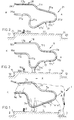
- Fig. 1 shows a part or an element of a first embodiment of the cubicle assembly according to the invention;
- fig. 2 shows a picture in accordance with figure 1 of a second embodiment of the cubicle assembly;
- fig. 3 shows an illustration in accordance with fig. 1 of a third embodiment of the cubicle assembly according to the invention;
- fig. 4 shows a picture in accordance with fig. 1, of a fourth embodiment of the cubicle assembly according to the invention; and
- fig. 5 shows a schematic representation of the movement of a heavy livestock cow whilst standing up.
- In figure 1 a part of a
cubicle assembly 1 is shown. The single-rowedcubicle assembly 1 comprises a number of cubicle partitions 7, which are placed at a distance from one another such that the cows come to lie fairly straight in the cubicle. If the cows can lie askew there is a risk of the teats being trodden on by the cow itself or by other cows. When there is too little room the cow can, however, only get up with difficulty, likewise with the risk of the teats being trodden on. In the second place the partition offers support for the heavy cows whose legs are relatively weak. The partitions are formed by essentially vertically placed frameworks 7 formed by tubes, which are attached at the side shown on the left in the drawing to fasteningpipes 6a and 6b which extend in the main direction of the shed where the cubicle assembly is placed and extend, in this case, perpendicular to the plane of the drawing. Thesepipes 6a and 6b are fixedly mounted by means of posts, not shown or other means, at suitable intervals. The pipe 6a also functions as head beam. The portion of the shed floor shown here comprises a passage way andentrance path 3 with dung discharge and a sloping lyingbed 2 which forms the floor of the cubicles, and which is raised by, for example, 15 and 18 cm in regard of thepassage 3 at the rear side or entrance side A by means of sill 4 and at the end side or head side K by means ofsill 5, respectively. Thepassage 3 shown on the left hand side of the drawing is, for example, intended for providing access to another series of cubicles, not shown. - The stability of the cubicle partition can be increased by known means. A leg could be considered (see, for example, figures 2 and 4) or a transverse rod passing relatively high above the partitions (not shown), which is connected by vertical rods to the rear of the cubicle partition. The connections with the
pipes 6a and 6b could also be designed to be spring like. - The cubicle partition 7 comprises two
pipe portions 7a and 7g extending substantially in a horizontal direction from fasteningpipes 6a and 6b to the entrance side. With its underside the pipe 7a is spaced at a height of 80 cm above the level of thecubicle bed 2 near thesill 5 and thepipe portion 7g is spaced with its upper side at approximately 1.50 m above that cubicle bed level. After approximately 60 cm the pipe portion 7a merges into apipe portion 7b extending obliquely downwards and rearwards, thepipe portions 7a and 7b leaving a side opening free, through which the cow, if in a recumbent position, can move with its head. When thepipe portion 7b has neared the surface of thecubicle bed 2 up to approximately 1/4 m, the pipe 7 is then bent to a pipe portion 7c extending obliquely upwards and backwards. By doing so space is created for the recumbent cow in a sideward direction, so that it gets extra space for the ribs and the rumen, but still it is prevented that the cow can lie entirely cross-wise. - On the rear side, at a horizontal distance of at most a 1/4 m from the sill 4, the pipe 7 merges via pipe portion 7d over into a slightly upwardly inclining and forwardly extending
pipe portion 7e. In this example thepipe portion 7e then merges into a pipe portion 7f which is more upwardly inclined, and connects to the saidpipe portion 7g. The distance between the rear surface of tube portion 7d and the front surface of pipe 6a/6b is here between 1.8 and 2.1 m. - So that the cow will use the cubicle in the intended manner, a beam 9 is attached to the
cubicle bed 2 by means not shown but otherwise known at approximately a distance of 1.7 - 1.9 m from the sill 4 , i.e. at a distance which is smaller than the distance between the front and hind legs of the cow concerned. This beam 9 has a height of approximately 15 to 25 cm and ensures that because of its location viz-a-viz the sill 4 and in conjunction with thehead beams 6a and 6b, that the cow, when walking in the direction X into the cubicle, will lower its front legs before the beam and will lie down in the position shown by L (see figure 5). If the cow, for whatever reason, wants to stand up again, it will then stretch its hind legs first and take up the position O, see figure 5. Then it will stretch its front legs to arrive at the standing position S, but meanwhile not come into contact with any structure member above it. Consequently the cow will neither be injured or wounded, nor, as far as its behaviour is concerned, will it have to reckon with any impeding structure members being present, which prevents further secondary reactive behaviour which might cause even more injury. - The fact that there are no structure members perceptible to the cow at all in the space above the cow has a further favourable effect on its behaviour and well-being.
- The average dimensions of a heavy livestock cow are now a length of ca. 2.5 m, a trunk length of ca. 1.65 m, a length of diagonal body measurement of ca. 1.55 m and a height at withers of ca. 1.45 m. Peaks upward (1.60 m) and downward (1.30 m) in height at withers occur. The present tendency of ever larger cows will continue in the coming years, even allowing for a future attainable height at withers of 1.65 m, in fact.
- In the figures 2, 3 and 4 other embodiments of cubicle assemblies according to the invention are shown, in the main the same reference numbers being used for corresponding parts, however with other decimal numerals.
- The part of the
cubicle assembly 11 shown in figure 2 comprises atubular cubicle partition 17, which differs from the cubicle partition 7 of figure 1 by the vertical course of thepipe portion 17b, by the bent design of thepipe portion 17c', 17c''(as a result of which more room is provided for the cow's abdomen), and by the elongated design of thepipe portion 17g and thus in connection with that the smaller angle between thepipe portions 17f and 17g. The lower side of thecubicle partition 17 is supported on thecubicle bed 12 by means of aleg 100, which is fixedly attached to thecubicle partition 17 and on thecubicle bed 12. In addition, instead of a beam a pipe 19a extending at a distance above the cubicle bed surface is provided, which is supported at suitable distances byupright pipe parts 19b attached on thecubicle bed 12. - In this case a
pipe 18 which extends parallel to thefastening pipes pipe portion 17g. The adjacentother cubicle partitions 17 are also attached to thispipe 18, which serves merely for increasing the fixed arrangement of thecubicle partitions 17, and in particular the resistance thereof against bending in the horizontal plane. Thispipe 18 is, as shown in the drawing, located outside the area which is covered by the cow which belongs to the category of heavy livestock, and is also shown. Thepipe 18 is located at 1.30 - 1.70 m above the cubicle bed, depending on the breed of heavy livestock concerned and above the height at withers of the cow. - The part of the
cubicle assembly 21 shown in figure 3 differs from that which is shown in figure 1 especially in that thepipe portion 27b extends for a part downwards and towards the head side, the pipe portion 27a and thepipe portion 27b near the pipe portion 27a leaving more space for the cow. In addition thepipe portion 27c is built up of twopipe portions 27c' and 27c '', which are at angle viz-a-viz each other, which is somewhat slighter than that of thepipe portions 17c' and 17c'' of figure 2. Again a stiffeningpipe 28 is attached to the pipe portion 27g, extending parallel to thefastening pipes sill 24, moreover, abeam 29a extending in a direction transverse to the plane of the drawing, is attached by means ofangle 29b irons to thecubicle bed 22. - Finally a part of the cubicle assembly 31 according to the invention is shown in figure 4, the
cubicle partition 37 of which is attached on the head side to an attachingpipe 36, and passes from there in a backward direction and in a substantially horizontal direction by means of apipe portion 37a, until apipe portion 37b which inclines in a pronounced way downwards and backwards branches off from there, which pipe portion is bent 1/4 m from the surface of thecubicle bed 32 into apipe portion 37c extending obliquely upwards and backwards.Pipe portion 37c merges at the rear end via acurve portion 37d into apipe portion 37e which inclines slightly upwards and extends to the head end, which pipe portion passes smoothly into horizontally located portion 37f, which passes smoothly into thepipe portion 37a. Here a second fastening pipe is missing, but the stability of the cubicle partition is ensured by the leg 38a, which is attached to thecubicle bed 32 by means offoot 38b and is attached by welds 38c to thecubicle partition 37.
Claims (10)
- Cubicle assembly for heavy livestock, comprising a number of partition members, such as frameworks, for dividing the cubicles for the animals, wherein for stiffening the partition members are connected to one another by means of connecting means which are located outside the range of movement of the body of the animal concerned, further comprising connecting means for steering the animal concerned to a lying position, which means comprise leg impeding means, which are arranged on or nearby the cubicle bed.
- Cubicle assembly according to claim 1, wherein the area between the partition members, that is covered by the movement of the shoulder and the back of the animal concerned is free of connecting means between the partition members.
- Cubicle assembly according to claim 2, wherein the lower limit of that area is at a height of 1.30 to 1.70 m above the cubicle bed.
- Cubicle assembly according to any one of the preceding claims, wherein the leg impeding means are formed an elongated structure member which extends above the cubicle bed, such as a pipe extending above the cubicle bed or a beam placed on the cubicle bed.
- Cubicle assembly according to claim 4, wherein the elongated structure member extends up to 15 to 25 cm above the cubicle bed.
- Cubicle assembly according to claim 4 or 5, wherein the elongated structure member is disposed at approximately 1.5 to 2 m, preferably 1.7-1.9 m from the rear end of the partition members.
- Cubicle assembly according to any one of the preceding claims, wherein the partition members are connected to one another by an upper beam.
- Cubicle assembly according to any one of the preceding claims, wherein the means for steering the animal to a lying position comprise means, which form a visible obstacle or the animal arranged at the front of the cubicle.
- Cubicle assembly according to claim 8, wherein the said means comprise a head beam, cubicle wall or the like.
- Cubicle assembly according to any one of the preceding claims, wherein the cubicle bed slopes upwards from the rear to the front.
Applications Claiming Priority (2)
| Application Number | Priority Date | Filing Date | Title |
|---|---|---|---|
| NL9302212 | 1993-12-20 | ||
| NL9302212A NL9302212A (en) | 1993-12-20 | 1993-12-20 | Cubicle assembly for livestock. |
Publications (2)
| Publication Number | Publication Date |
|---|---|
| EP0659336A1 true EP0659336A1 (en) | 1995-06-28 |
| EP0659336B1 EP0659336B1 (en) | 1998-07-08 |
Family
ID=19863283
Family Applications (1)
| Application Number | Title | Priority Date | Filing Date |
|---|---|---|---|
| EP94203693A Expired - Lifetime EP0659336B1 (en) | 1993-12-20 | 1994-12-20 | Cubicle assembly for heavy livestock |
Country Status (6)
| Country | Link |
|---|---|
| EP (1) | EP0659336B1 (en) |
| AT (1) | ATE167979T1 (en) |
| DE (1) | DE69411522T2 (en) |
| DK (1) | DK0659336T3 (en) |
| ES (1) | ES2121147T3 (en) |
| NL (1) | NL9302212A (en) |
Cited By (4)
| Publication number | Priority date | Publication date | Assignee | Title |
|---|---|---|---|---|
| GB2336988A (en) * | 1998-05-09 | 1999-11-10 | Robert James Muldrew | Cattle stall system |
| NL1033422C2 (en) | 2007-02-19 | 2008-08-20 | Andringa Holding B V R | Limiter for a berth in a walking stable. |
| GB2470425A (en) * | 2009-05-23 | 2010-11-24 | Liberty Cow Products Ltd | Animal positioning rail |
| EP2409824A1 (en) | 2010-07-22 | 2012-01-25 | Politsch Kunststofftechnik GmbH | Water tank system for energy efficient calibration and cooling of plastic profiles |
Families Citing this family (1)
| Publication number | Priority date | Publication date | Assignee | Title |
|---|---|---|---|---|
| CN106069799B (en) * | 2016-07-27 | 2022-04-19 | 孟克达来 | Multifunctional movable shed |
Citations (4)
| Publication number | Priority date | Publication date | Assignee | Title |
|---|---|---|---|---|
| US1994193A (en) * | 1934-06-02 | 1935-03-12 | Starline | Stall |
| CH226864A (en) * | 1942-06-22 | 1943-05-15 | Paul Grolimund Aime | Cattle ranch, especially for cattle stalls. |
| NL8005338A (en) * | 1980-09-24 | 1982-04-16 | Ametrac Mechanisation B V | Animal stall neck tether - comprises tube bent vertical inverted V=shape to allow bending during feeding |
| DE8524590U1 (en) * | 1985-08-28 | 1985-10-10 | Erhard Höhne GmbH, 8801 Burgbernheim | Device for the lateral separation of livestock stalls, in particular for cattle |
Family Cites Families (1)
| Publication number | Priority date | Publication date | Assignee | Title |
|---|---|---|---|---|
| NL9000085A (en) * | 1990-01-12 | 1991-08-01 | Boer B V De | LIGBOX SEPARATION. |
-
1993
- 1993-12-20 NL NL9302212A patent/NL9302212A/en not_active Application Discontinuation
-
1994
- 1994-12-20 DK DK94203693T patent/DK0659336T3/en active
- 1994-12-20 ES ES94203693T patent/ES2121147T3/en not_active Expired - Lifetime
- 1994-12-20 AT AT94203693T patent/ATE167979T1/en not_active IP Right Cessation
- 1994-12-20 EP EP94203693A patent/EP0659336B1/en not_active Expired - Lifetime
- 1994-12-20 DE DE69411522T patent/DE69411522T2/en not_active Expired - Fee Related
Patent Citations (4)
| Publication number | Priority date | Publication date | Assignee | Title |
|---|---|---|---|---|
| US1994193A (en) * | 1934-06-02 | 1935-03-12 | Starline | Stall |
| CH226864A (en) * | 1942-06-22 | 1943-05-15 | Paul Grolimund Aime | Cattle ranch, especially for cattle stalls. |
| NL8005338A (en) * | 1980-09-24 | 1982-04-16 | Ametrac Mechanisation B V | Animal stall neck tether - comprises tube bent vertical inverted V=shape to allow bending during feeding |
| DE8524590U1 (en) * | 1985-08-28 | 1985-10-10 | Erhard Höhne GmbH, 8801 Burgbernheim | Device for the lateral separation of livestock stalls, in particular for cattle |
Cited By (5)
| Publication number | Priority date | Publication date | Assignee | Title |
|---|---|---|---|---|
| GB2336988A (en) * | 1998-05-09 | 1999-11-10 | Robert James Muldrew | Cattle stall system |
| NL1033422C2 (en) | 2007-02-19 | 2008-08-20 | Andringa Holding B V R | Limiter for a berth in a walking stable. |
| GB2470425A (en) * | 2009-05-23 | 2010-11-24 | Liberty Cow Products Ltd | Animal positioning rail |
| GB2470425B (en) * | 2009-05-23 | 2011-04-20 | Liberty Cow Products Ltd | Maintaining an animal in a preferred orientation |
| EP2409824A1 (en) | 2010-07-22 | 2012-01-25 | Politsch Kunststofftechnik GmbH | Water tank system for energy efficient calibration and cooling of plastic profiles |
Also Published As
| Publication number | Publication date |
|---|---|
| DE69411522T2 (en) | 1999-03-25 |
| DE69411522D1 (en) | 1998-08-13 |
| DK0659336T3 (en) | 1999-04-19 |
| EP0659336B1 (en) | 1998-07-08 |
| ATE167979T1 (en) | 1998-07-15 |
| ES2121147T3 (en) | 1998-11-16 |
| NL9302212A (en) | 1995-07-17 |
Similar Documents
| Publication | Publication Date | Title |
|---|---|---|
| AU704479B2 (en) | A construction including an implement for milking animals | |
| US7849819B2 (en) | Brisket tube hanger for cow stall assembly | |
| EP0659336B1 (en) | Cubicle assembly for heavy livestock | |
| HU216785B (en) | Front positioning rail for milking parlour and a milking parlour provided with that | |
| CA2938834C (en) | Flexible neckrail coupling | |
| EP2120534B1 (en) | Lying box for a loose house | |
| US1839313A (en) | Stall construction | |
| US4350117A (en) | Free stall construction | |
| Honeyman et al. | Performance of a Swedish deep-bedded feeder pig production system in Iowa | |
| EP0068716A1 (en) | Pen for the delivery and nursing of livestock | |
| EP0437298B1 (en) | Cubicle partition | |
| US3392709A (en) | Stall arrangement for facilitating the milking operation in barns | |
| US20070006817A1 (en) | Animal stall assembly | |
| US5809937A (en) | Farrowing crate | |
| Anderson | Dairy cattle behavior: Cows interacting with their workplace | |
| US4649864A (en) | Device for keeping animals separated and tied up in stalls | |
| EP1075178A1 (en) | Standing cubicle partitions | |
| JP2025524676A (en) | Cubicles and barns | |
| US2737922A (en) | Comfort stall structure for cows | |
| JPS6345887Y2 (en) | ||
| WO2024091119A1 (en) | Cubicle and shed | |
| CN217986301U (en) | Adjustable delivery cage for fattening pig breeding | |
| JPS6337807Y2 (en) | ||
| EP0634095A1 (en) | A construction for automatically milking animals | |
| JPS5978634A (en) | Floor structure of pig laboring house |
Legal Events
| Date | Code | Title | Description |
|---|---|---|---|
| PUAI | Public reference made under article 153(3) epc to a published international application that has entered the european phase |
Free format text: ORIGINAL CODE: 0009012 |
|
| 17P | Request for examination filed |
Effective date: 19950323 |
|
| AK | Designated contracting states |
Kind code of ref document: A1 Designated state(s): AT BE CH DE DK ES FR GB IE IT LI LU NL PT SE |
|
| 17Q | First examination report despatched |
Effective date: 19970210 |
|
| GRAG | Despatch of communication of intention to grant |
Free format text: ORIGINAL CODE: EPIDOS AGRA |
|
| GRAG | Despatch of communication of intention to grant |
Free format text: ORIGINAL CODE: EPIDOS AGRA |
|
| GRAH | Despatch of communication of intention to grant a patent |
Free format text: ORIGINAL CODE: EPIDOS IGRA |
|
| GRAH | Despatch of communication of intention to grant a patent |
Free format text: ORIGINAL CODE: EPIDOS IGRA |
|
| GRAA | (expected) grant |
Free format text: ORIGINAL CODE: 0009210 |
|
| RAP1 | Party data changed (applicant data changed or rights of an application transferred) |
Owner name: REDNIPS HOLDING B.V. |
|
| AK | Designated contracting states |
Kind code of ref document: B1 Designated state(s): AT BE CH DE DK ES FR GB IE IT LI LU NL PT SE |
|
| REF | Corresponds to: |
Ref document number: 167979 Country of ref document: AT Date of ref document: 19980715 Kind code of ref document: T |
|
| REG | Reference to a national code |
Ref country code: CH Ref legal event code: EP |
|
| REF | Corresponds to: |
Ref document number: 69411522 Country of ref document: DE Date of ref document: 19980813 |
|
| REG | Reference to a national code |
Ref country code: IE Ref legal event code: FG4D |
|
| REG | Reference to a national code |
Ref country code: CH Ref legal event code: NV Representative=s name: DIPL.-ING. ETH H. R. WERFFELI PATENTANWALT |
|
| REG | Reference to a national code |
Ref country code: ES Ref legal event code: FG2A Ref document number: 2121147 Country of ref document: ES Kind code of ref document: T3 |
|
| ET | Fr: translation filed | ||
| REG | Reference to a national code |
Ref country code: PT Ref legal event code: SC4A Free format text: AVAILABILITY OF NATIONAL TRANSLATION Effective date: 19981007 |
|
| REG | Reference to a national code |
Ref country code: DK Ref legal event code: T3 |
|
| PLBE | No opposition filed within time limit |
Free format text: ORIGINAL CODE: 0009261 |
|
| STAA | Information on the status of an ep patent application or granted ep patent |
Free format text: STATUS: NO OPPOSITION FILED WITHIN TIME LIMIT |
|
| 26N | No opposition filed | ||
| PGFP | Annual fee paid to national office [announced via postgrant information from national office to epo] |
Ref country code: PT Payment date: 20011123 Year of fee payment: 8 |
|
| PGFP | Annual fee paid to national office [announced via postgrant information from national office to epo] |
Ref country code: LU Payment date: 20011129 Year of fee payment: 8 |
|
| PGFP | Annual fee paid to national office [announced via postgrant information from national office to epo] |
Ref country code: IE Payment date: 20011206 Year of fee payment: 8 |
|
| PGFP | Annual fee paid to national office [announced via postgrant information from national office to epo] |
Ref country code: SE Payment date: 20011210 Year of fee payment: 8 |
|
| PGFP | Annual fee paid to national office [announced via postgrant information from national office to epo] |
Ref country code: BE Payment date: 20011213 Year of fee payment: 8 |
|
| PGFP | Annual fee paid to national office [announced via postgrant information from national office to epo] |
Ref country code: ES Payment date: 20011217 Year of fee payment: 8 Ref country code: AT Payment date: 20011217 Year of fee payment: 8 |
|
| PGFP | Annual fee paid to national office [announced via postgrant information from national office to epo] |
Ref country code: FR Payment date: 20011220 Year of fee payment: 8 |
|
| PGFP | Annual fee paid to national office [announced via postgrant information from national office to epo] |
Ref country code: CH Payment date: 20011224 Year of fee payment: 8 |
|
| REG | Reference to a national code |
Ref country code: GB Ref legal event code: IF02 |
|
| PG25 | Lapsed in a contracting state [announced via postgrant information from national office to epo] |
Ref country code: LU Free format text: LAPSE BECAUSE OF NON-PAYMENT OF DUE FEES Effective date: 20021220 Ref country code: IE Free format text: LAPSE BECAUSE OF NON-PAYMENT OF DUE FEES Effective date: 20021220 Ref country code: AT Free format text: LAPSE BECAUSE OF NON-PAYMENT OF DUE FEES Effective date: 20021220 |
|
| PG25 | Lapsed in a contracting state [announced via postgrant information from national office to epo] |
Ref country code: SE Free format text: LAPSE BECAUSE OF NON-PAYMENT OF DUE FEES Effective date: 20021221 Ref country code: ES Free format text: LAPSE BECAUSE OF NON-PAYMENT OF DUE FEES Effective date: 20021221 |
|
| PG25 | Lapsed in a contracting state [announced via postgrant information from national office to epo] |
Ref country code: LI Free format text: LAPSE BECAUSE OF NON-PAYMENT OF DUE FEES Effective date: 20021231 Ref country code: CH Free format text: LAPSE BECAUSE OF NON-PAYMENT OF DUE FEES Effective date: 20021231 Ref country code: BE Free format text: LAPSE BECAUSE OF NON-PAYMENT OF DUE FEES Effective date: 20021231 |
|
| BERE | Be: lapsed |
Owner name: *REDNIPS HOLDING B.V. Effective date: 20021231 |
|
| PG25 | Lapsed in a contracting state [announced via postgrant information from national office to epo] |
Ref country code: PT Free format text: LAPSE BECAUSE OF NON-PAYMENT OF DUE FEES Effective date: 20030630 |
|
| EUG | Se: european patent has lapsed | ||
| REG | Reference to a national code |
Ref country code: CH Ref legal event code: PL |
|
| PG25 | Lapsed in a contracting state [announced via postgrant information from national office to epo] |
Ref country code: FR Free format text: LAPSE BECAUSE OF NON-PAYMENT OF DUE FEES Effective date: 20030901 |
|
| REG | Reference to a national code |
Ref country code: PT Ref legal event code: MM4A Free format text: LAPSE DUE TO NON-PAYMENT OF FEES Effective date: 20030630 |
|
| REG | Reference to a national code |
Ref country code: IE Ref legal event code: MM4A |
|
| REG | Reference to a national code |
Ref country code: FR Ref legal event code: ST |
|
| REG | Reference to a national code |
Ref country code: ES Ref legal event code: FD2A Effective date: 20021221 |
|
| PG25 | Lapsed in a contracting state [announced via postgrant information from national office to epo] |
Ref country code: IT Free format text: LAPSE BECAUSE OF NON-PAYMENT OF DUE FEES;WARNING: LAPSES OF ITALIAN PATENTS WITH EFFECTIVE DATE BEFORE 2007 MAY HAVE OCCURRED AT ANY TIME BEFORE 2007. THE CORRECT EFFECTIVE DATE MAY BE DIFFERENT FROM THE ONE RECORDED. Effective date: 20051220 |
|
| PGFP | Annual fee paid to national office [announced via postgrant information from national office to epo] |
Ref country code: GB Payment date: 20061122 Year of fee payment: 13 |
|
| PGFP | Annual fee paid to national office [announced via postgrant information from national office to epo] |
Ref country code: DE Payment date: 20061227 Year of fee payment: 13 |
|
| PGFP | Annual fee paid to national office [announced via postgrant information from national office to epo] |
Ref country code: DK Payment date: 20061228 Year of fee payment: 13 |
|
| PGFP | Annual fee paid to national office [announced via postgrant information from national office to epo] |
Ref country code: NL Payment date: 20061229 Year of fee payment: 13 |
|
| REG | Reference to a national code |
Ref country code: DK Ref legal event code: EBP |
|
| GBPC | Gb: european patent ceased through non-payment of renewal fee |
Effective date: 20071220 |
|
| NLV4 | Nl: lapsed or anulled due to non-payment of the annual fee |
Effective date: 20080701 |
|
| PG25 | Lapsed in a contracting state [announced via postgrant information from national office to epo] |
Ref country code: DE Free format text: LAPSE BECAUSE OF NON-PAYMENT OF DUE FEES Effective date: 20080701 |
|
| PG25 | Lapsed in a contracting state [announced via postgrant information from national office to epo] |
Ref country code: NL Free format text: LAPSE BECAUSE OF NON-PAYMENT OF DUE FEES Effective date: 20080701 |
|
| PG25 | Lapsed in a contracting state [announced via postgrant information from national office to epo] |
Ref country code: GB Free format text: LAPSE BECAUSE OF NON-PAYMENT OF DUE FEES Effective date: 20071220 |
|
| PG25 | Lapsed in a contracting state [announced via postgrant information from national office to epo] |
Ref country code: DK Free format text: LAPSE BECAUSE OF NON-PAYMENT OF DUE FEES Effective date: 20080102 |