EP0659516B1 - Appareil de soudage par ultrasons - Google Patents
Appareil de soudage par ultrasons Download PDFInfo
- Publication number
- EP0659516B1 EP0659516B1 EP94117134A EP94117134A EP0659516B1 EP 0659516 B1 EP0659516 B1 EP 0659516B1 EP 94117134 A EP94117134 A EP 94117134A EP 94117134 A EP94117134 A EP 94117134A EP 0659516 B1 EP0659516 B1 EP 0659516B1
- Authority
- EP
- European Patent Office
- Prior art keywords
- resonator
- ultrasonic welding
- welding apparatus
- transducer
- coupled
- Prior art date
- Legal status (The legal status is an assumption and is not a legal conclusion. Google has not performed a legal analysis and makes no representation as to the accuracy of the status listed.)
- Expired - Lifetime
Links
- 238000003466 welding Methods 0.000 title claims abstract description 24
- 230000010355 oscillation Effects 0.000 claims description 4
- 230000008878 coupling Effects 0.000 claims description 3
- 238000010168 coupling process Methods 0.000 claims description 3
- 238000005859 coupling reaction Methods 0.000 claims description 3
- 230000009466 transformation Effects 0.000 claims description 2
- 229910052751 metal Inorganic materials 0.000 description 4
- 239000002184 metal Substances 0.000 description 4
- 150000002739 metals Chemical class 0.000 description 3
- 238000002604 ultrasonography Methods 0.000 description 3
- RYGMFSIKBFXOCR-UHFFFAOYSA-N Copper Chemical compound [Cu] RYGMFSIKBFXOCR-UHFFFAOYSA-N 0.000 description 1
- 229910052782 aluminium Inorganic materials 0.000 description 1
- XAGFODPZIPBFFR-UHFFFAOYSA-N aluminium Chemical compound [Al] XAGFODPZIPBFFR-UHFFFAOYSA-N 0.000 description 1
- 229910052802 copper Inorganic materials 0.000 description 1
- 239000010949 copper Substances 0.000 description 1
- 238000011161 development Methods 0.000 description 1
- 230000018109 developmental process Effects 0.000 description 1
- 230000002349 favourable effect Effects 0.000 description 1
- 239000000463 material Substances 0.000 description 1
- 229920003023 plastic Polymers 0.000 description 1
- 239000004033 plastic Substances 0.000 description 1
- 239000011343 solid material Substances 0.000 description 1
- 230000003068 static effect Effects 0.000 description 1
Images
Classifications
-
- B—PERFORMING OPERATIONS; TRANSPORTING
- B23—MACHINE TOOLS; METAL-WORKING NOT OTHERWISE PROVIDED FOR
- B23K—SOLDERING OR UNSOLDERING; WELDING; CLADDING OR PLATING BY SOLDERING OR WELDING; CUTTING BY APPLYING HEAT LOCALLY, e.g. FLAME CUTTING; WORKING BY LASER BEAM
- B23K20/00—Non-electric welding by applying impact or other pressure, with or without the application of heat, e.g. cladding or plating
- B23K20/10—Non-electric welding by applying impact or other pressure, with or without the application of heat, e.g. cladding or plating making use of vibrations, e.g. ultrasonic welding
Definitions
- the invention relates to an ultrasonic welding device with a first sound transducer that executes longitudinal vibrations and a rod-shaped resonator of length lambda / 2 or an integral multiple thereof, which is coupled to the sound transducer on one end face.
- Ultrasonic welding devices are used more and more in today's world. In addition to plastics, ultrasound can also be used to weld metals such as aluminum or copper.
- a device for welding with ultrasound in which the weld metal is supplied with the vibration energy via two mechanically non-coupled exciters which oscillate in phase or in opposite phase.
- the exciters are ultrasonic transducers, which are each arranged at one end of a sonotrode.
- Two workpieces to be welded are placed between the sonotrode tips. The two sonotrode tips and thus the two workpieces to be welded are pressed together by a force.
- a workpiece can also be arranged between the two sonotrode tips, into which the energy from both sonotrodes is then introduced.
- the workpiece moved by the sonotrodes is pressed by an external force onto a workpiece that is at rest.
- a second longitudinal vibrating transducer is coupled to the free end face of the resonator and vibrates synchronously with the first sound transducer.
- the second sound transducer in turn emits energy to the resonator. This almost doubles the energy available for welding. Larger objects can thus be welded together.
- Another advantage of the design of an ultrasonic welding device according to the invention is that the workpieces can be pressed against the resonator at the maximum vibration. With conventional ultrasonic welding machines, however, the workpieces can only be arranged next to the maximum vibration, starting from the maximum vibration of the resonator on the open end face.
- a special embodiment of the invention provides that the length of the resonator corresponds to an even multiple of lambda / 2. This is located exactly in the middle between the two converters a maximum vibration. This means that the point at which the objects to be welded are pressed against the resonator is in the middle between the two transducers, which makes them easily accessible. Furthermore, with such an arrangement, the ultrasonic welding device can be made symmetrical.
- the resonator is coupled to the transducer by means of transformation pieces.
- the amplitude with which the transducers are coupled to the resonator can be set to optimum values.
- Another embodiment of the invention provides that the electrical conduction to the second transducer takes place axially through the resonator. Since not only solid material but also tubular material can be used as the resonator, the resonator can in any case be provided with an axial bore through which the electrical line can be led to the second converter. It is thus advantageously possible to supply the second converter with energy without any disruptive lines running outside.
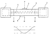
- the only drawing shows a schematic arrangement of an ultrasonic welding device according to the invention.
- an ultrasonic welding device has a first transducer 1 and a second transducer 2.
- the two transducers 1, 2 are connected to a resonator 3.
- the coupling takes place on the two end faces of the resonator 3.
- the transducers 1, 2 have a vibration maximum M at the coupling point.
- the resonator 3 has the length two lambda / 2, so that a vibration maximum M is also formed in the middle of the transducer.
- the amplitude curve is shown schematically below the resonator 3.
- a workpiece to be welded is pressed against the resonator 3 with a pressure P.
- the workpiece 4 is arranged so that the center of the workpiece 4 is at the maximum vibration M. It is thus possible to use the maximum amplitude of the ultrasonic vibration.
- the workpiece 4 In a conventional ultrasonic welding device, the workpiece 4 would have to be arranged next to the oscillation maximum M, since the resonator rod only extends up to the oscillation maximum M.
Landscapes
- Engineering & Computer Science (AREA)
- Mechanical Engineering (AREA)
- Pressure Welding/Diffusion-Bonding (AREA)
- Apparatuses For Generation Of Mechanical Vibrations (AREA)
- Lining Or Joining Of Plastics Or The Like (AREA)
- Manufacturing Of Electrical Connectors (AREA)
- Ultra Sonic Daignosis Equipment (AREA)
Claims (4)
- Appareil de soudage par ultrasons comprenant un premier transducteur (1) qui exécute des vibrations longitudinales de longueur d'onde λ et un résonateur (3) en forme de tige dont la longueur est égale à λ/2 ou à un multiple de cette valeur et qui est accouplé au transducteur (1) sur un côté frontal, caractérisé par le fait qu'un deuxième transducteur (2) exécutant des vibrations longitudinales est couplé au côté frontal libre du résonateur (3), et qu'il oscille en synchronisme avec le premier transducteur (1).
- Appareil de soudage par ultrasons selon la revendication 1, caractérisé par le fait que la longueur du résonateur (3) correspond à un multiple entier de λ/2.
- Appareil de soudage par ultrasons selon la revendication 1 ou 2, caractérisé par le fait que le couplage du résonateur (3) aux transducteurs (1, 2) a lieu au moyen d'éléments de transformation.
- Appareil de soudage par ultrasons selon l'une des revendications 1 à 3, caractérisé par le fait que l'amenée du courant au deuxième transducteur (2) a lieu axialement à travers le résonateur (3).
Applications Claiming Priority (2)
| Application Number | Priority Date | Filing Date | Title |
|---|---|---|---|
| DE4344186 | 1993-12-23 | ||
| DE4344186A DE4344186C1 (de) | 1993-12-23 | 1993-12-23 | Ultraschallschweißgerät |
Publications (3)
| Publication Number | Publication Date |
|---|---|
| EP0659516A1 EP0659516A1 (fr) | 1995-06-28 |
| EP0659516B1 true EP0659516B1 (fr) | 1997-03-05 |
| EP0659516B2 EP0659516B2 (fr) | 2000-07-26 |
Family
ID=6506019
Family Applications (1)
| Application Number | Title | Priority Date | Filing Date |
|---|---|---|---|
| EP94117134A Expired - Lifetime EP0659516B2 (fr) | 1993-12-23 | 1994-10-29 | Appareil de soudage par ultrasons |
Country Status (5)
| Country | Link |
|---|---|
| EP (1) | EP0659516B2 (fr) |
| JP (1) | JPH07276068A (fr) |
| AT (1) | ATE149399T1 (fr) |
| DE (2) | DE4344186C1 (fr) |
| ES (1) | ES2098847T5 (fr) |
Families Citing this family (5)
| Publication number | Priority date | Publication date | Assignee | Title |
|---|---|---|---|---|
| DE4439470C2 (de) * | 1994-11-08 | 1999-05-20 | Herrmann Ultraschalltechnik | Vorrichtung zum Ultraschallbearbeiten eines Werkstücks |
| DE19545132C2 (de) * | 1995-12-01 | 1998-05-20 | Branson Ultraschall | Orbitalreibschweißmaschine |
| JP3290632B2 (ja) * | 1999-01-06 | 2002-06-10 | 株式会社アルテクス | 超音波振動接合装置 |
| KR100330668B1 (ko) * | 1999-08-26 | 2002-03-29 | 이천웅 | 초음파 용접기의 비틀림진동 발생장치 |
| CN102145434A (zh) * | 2010-02-05 | 2011-08-10 | 严锦璇 | 双头同步超声波金属焊接装置 |
Family Cites Families (3)
| Publication number | Priority date | Publication date | Assignee | Title |
|---|---|---|---|---|
| US3166840A (en) † | 1961-06-28 | 1965-01-26 | Aeroprojects Inc | Apparatus and method for introducing high levels of vibratory energy to a work area |
| US3209448A (en) † | 1962-03-12 | 1965-10-05 | Sonobond Corp | Vibratory welding method and apparatus |
| DE2253528A1 (de) * | 1972-11-02 | 1974-05-09 | Reimar Prof Dr Phil Pohlman | Verfahren, die schweissleistung beim ultraschall-schweissprozess zu erhoehen |
-
1993
- 1993-12-23 DE DE4344186A patent/DE4344186C1/de not_active Expired - Lifetime
-
1994
- 1994-10-29 ES ES94117134T patent/ES2098847T5/es not_active Expired - Lifetime
- 1994-10-29 EP EP94117134A patent/EP0659516B2/fr not_active Expired - Lifetime
- 1994-10-29 AT AT94117134T patent/ATE149399T1/de active
- 1994-10-29 DE DE59401935T patent/DE59401935D1/de not_active Expired - Lifetime
- 1994-12-21 JP JP6318839A patent/JPH07276068A/ja active Pending
Also Published As
| Publication number | Publication date |
|---|---|
| EP0659516B2 (fr) | 2000-07-26 |
| EP0659516A1 (fr) | 1995-06-28 |
| DE4344186C1 (de) | 1995-01-26 |
| ATE149399T1 (de) | 1997-03-15 |
| ES2098847T3 (es) | 1997-05-01 |
| JPH07276068A (ja) | 1995-10-24 |
| DE59401935D1 (de) | 1997-04-10 |
| ES2098847T5 (es) | 2000-11-01 |
Similar Documents
| Publication | Publication Date | Title |
|---|---|---|
| DE69406165T2 (de) | Vorrichtung zur Ultraschallversiegelung | |
| EP2566652B1 (fr) | Dispositif et méthode de soudage par ultrasons | |
| DE2312446C3 (de) | Elektromechanischer Schwinger für Schweißgeräte | |
| EP2945793B1 (fr) | Dispositif de soudage par ultrasons pourvu d'un contre-outil à découplage vibratoire | |
| DE2532029A1 (de) | Verfahren zur beaufschlagung einer fluessigkeit mit hochfrequenter schallenergie und vorrichtung zur durchfuehrung des verfahrens | |
| DE102008002744A1 (de) | Ultraschallschwingeinheit mit Halterung | |
| EP0857088A1 (fr) | Dispositif pour injecter des ultrasons dans une substance liquide ou pateuse | |
| DE10295945B4 (de) | Symmetrisches drehbares Ultraschallhorn | |
| DE2628203A1 (de) | Verfahren zur ultraschallverschweissung von zwei thermoplastischen werkstuecken | |
| DE1472357A1 (de) | Mit Torsionsschwingungsenergie arbeitende Vorrichtung | |
| DE2711305A1 (de) | Vorrichtung zur erzeugung von ultraschallwellen | |
| DE1948844A1 (de) | Horn fuer Schall- oder Ultraschallbearbeitung | |
| DE2047883C3 (de) | Schwingungsübertrager für eine Ultraschallvorrichtung | |
| EP0659516B1 (fr) | Appareil de soudage par ultrasons | |
| DE2743018A1 (de) | Verfahren und einrichtung zur verbindung metallischer werkstuecke mit hochfrequenter energie (hf-schweissverfahren und -geraet) | |
| EP3713682B1 (fr) | Unité de vibration ultrasonore avec amortissement | |
| WO2000029178A1 (fr) | Dispositif de coupe a ultrasons | |
| DE19859355C2 (de) | Vorrichtung zum Verbinden von metallischen Werkstoffen | |
| EP2663416B1 (fr) | Procédé et dispositif pour conférer un mouvement oscillant à une masse | |
| DE1704178A1 (de) | Verfahren zum kontinuierlichen Nahtschweissen von Folien aus thermoplastischem Material mittels Ultraschall | |
| WO1999046061A1 (fr) | Procede pour activer une monture de tamis avec des ultrasons | |
| DE6901110U (de) | Elektromechanischer ultraschallenergieerzeuger, insbesondere zum verschweissen von kunststoffbaendern. | |
| DE2414474C2 (fr) | ||
| DE10114672A1 (de) | Ultraschallschwinger | |
| DE748684C (de) | Vorrichtung zum elektrischen Punktschweissen, insbesondere von Aluminiumlegierungen |
Legal Events
| Date | Code | Title | Description |
|---|---|---|---|
| PUAI | Public reference made under article 153(3) epc to a published international application that has entered the european phase |
Free format text: ORIGINAL CODE: 0009012 |
|
| AK | Designated contracting states |
Kind code of ref document: A1 Designated state(s): AT BE CH DE ES FR GB IT LI NL PT SE |
|
| 17P | Request for examination filed |
Effective date: 19950524 |
|
| 17Q | First examination report despatched |
Effective date: 19960119 |
|
| GRAG | Despatch of communication of intention to grant |
Free format text: ORIGINAL CODE: EPIDOS AGRA |
|
| GRAH | Despatch of communication of intention to grant a patent |
Free format text: ORIGINAL CODE: EPIDOS IGRA |
|
| GRAH | Despatch of communication of intention to grant a patent |
Free format text: ORIGINAL CODE: EPIDOS IGRA |
|
| GRAA | (expected) grant |
Free format text: ORIGINAL CODE: 0009210 |
|
| AK | Designated contracting states |
Kind code of ref document: B1 Designated state(s): AT BE CH DE ES FR GB IT LI NL PT SE |
|
| REF | Corresponds to: |
Ref document number: 149399 Country of ref document: AT Date of ref document: 19970315 Kind code of ref document: T |
|
| REG | Reference to a national code |
Ref country code: CH Ref legal event code: NV Representative=s name: DR. CONRAD A. RIEDERER PATENTANWALT Ref country code: CH Ref legal event code: EP |
|
| GBT | Gb: translation of ep patent filed (gb section 77(6)(a)/1977) |
Effective date: 19970305 |
|
| REF | Corresponds to: |
Ref document number: 59401935 Country of ref document: DE Date of ref document: 19970410 |
|
| REG | Reference to a national code |
Ref country code: ES Ref legal event code: FG2A Ref document number: 2098847 Country of ref document: ES Kind code of ref document: T3 |
|
| ITF | It: translation for a ep patent filed | ||
| REG | Reference to a national code |
Ref country code: PT Ref legal event code: SC4A Free format text: AVAILABILITY OF NATIONAL TRANSLATION Effective date: 19970327 |
|
| ET | Fr: translation filed | ||
| PLAV | Examination of admissibility of opposition |
Free format text: ORIGINAL CODE: EPIDOS OPEX |
|
| PLBI | Opposition filed |
Free format text: ORIGINAL CODE: 0009260 |
|
| PLBF | Reply of patent proprietor to notice(s) of opposition |
Free format text: ORIGINAL CODE: EPIDOS OBSO |
|
| 26 | Opposition filed |
Opponent name: SIEMENS AG Effective date: 19971205 |
|
| NLR1 | Nl: opposition has been filed with the epo |
Opponent name: SIEMENS AG |
|
| PLBF | Reply of patent proprietor to notice(s) of opposition |
Free format text: ORIGINAL CODE: EPIDOS OBSO |
|
| PLAW | Interlocutory decision in opposition |
Free format text: ORIGINAL CODE: EPIDOS IDOP |
|
| PLAW | Interlocutory decision in opposition |
Free format text: ORIGINAL CODE: EPIDOS IDOP |
|
| PUAH | Patent maintained in amended form |
Free format text: ORIGINAL CODE: 0009272 |
|
| STAA | Information on the status of an ep patent application or granted ep patent |
Free format text: STATUS: PATENT MAINTAINED AS AMENDED |
|
| 27A | Patent maintained in amended form |
Effective date: 20000726 |
|
| AK | Designated contracting states |
Kind code of ref document: B2 Designated state(s): AT BE CH DE ES FR GB IT LI NL PT SE |
|
| REG | Reference to a national code |
Ref country code: CH Ref legal event code: AEN Free format text: AUFRECHTERHALTUNG DES PATENTES IN GEAENDERTER FORM |
|
| GBTA | Gb: translation of amended ep patent filed (gb section 77(6)(b)/1977) | ||
| ET3 | Fr: translation filed ** decision concerning opposition | ||
| NLR2 | Nl: decision of opposition | ||
| ITF | It: translation for a ep patent filed | ||
| REG | Reference to a national code |
Ref country code: ES Ref legal event code: DC2A Kind code of ref document: T5 Effective date: 20000911 |
|
| NLR3 | Nl: receipt of modified translations in the netherlands language after an opposition procedure | ||
| REG | Reference to a national code |
Ref country code: GB Ref legal event code: IF02 |
|
| REG | Reference to a national code |
Ref country code: CH Ref legal event code: NV Representative=s name: RIEDERER HASLER & PARTNER PATENTANWAELTE AG |
|
| REG | Reference to a national code |
Ref country code: DE Ref legal event code: R082 Ref document number: 59401935 Country of ref document: DE Representative=s name: PATENTANWAELTE DIMMERLING & HUWER, DE |
|
| PGFP | Annual fee paid to national office [announced via postgrant information from national office to epo] |
Ref country code: AT Payment date: 20131021 Year of fee payment: 20 Ref country code: DE Payment date: 20131031 Year of fee payment: 20 Ref country code: SE Payment date: 20131022 Year of fee payment: 20 Ref country code: FR Payment date: 20131018 Year of fee payment: 20 Ref country code: CH Payment date: 20131023 Year of fee payment: 20 Ref country code: PT Payment date: 20130429 Year of fee payment: 20 Ref country code: GB Payment date: 20131022 Year of fee payment: 20 Ref country code: BE Payment date: 20131021 Year of fee payment: 20 |
|
| PGFP | Annual fee paid to national office [announced via postgrant information from national office to epo] |
Ref country code: ES Payment date: 20131022 Year of fee payment: 20 Ref country code: IT Payment date: 20131025 Year of fee payment: 20 Ref country code: NL Payment date: 20131021 Year of fee payment: 20 |
|
| REG | Reference to a national code |
Ref country code: DE Ref legal event code: R071 Ref document number: 59401935 Country of ref document: DE |
|
| REG | Reference to a national code |
Ref country code: NL Ref legal event code: V4 Effective date: 20141029 Ref country code: PT Ref legal event code: MM4A Free format text: MAXIMUM VALIDITY LIMIT REACHED Effective date: 20141029 |
|
| REG | Reference to a national code |
Ref country code: CH Ref legal event code: PL |
|
| REG | Reference to a national code |
Ref country code: GB Ref legal event code: PE20 Expiry date: 20141028 |
|
| REG | Reference to a national code |
Ref country code: SE Ref legal event code: EUG |
|
| REG | Reference to a national code |
Ref country code: AT Ref legal event code: MK07 Ref document number: 149399 Country of ref document: AT Kind code of ref document: T Effective date: 20141029 |
|
| REG | Reference to a national code |
Ref country code: ES Ref legal event code: FD2A Effective date: 20150108 |
|
| PG25 | Lapsed in a contracting state [announced via postgrant information from national office to epo] |
Ref country code: ES Free format text: LAPSE BECAUSE OF EXPIRATION OF PROTECTION Effective date: 20141030 Ref country code: GB Free format text: LAPSE BECAUSE OF EXPIRATION OF PROTECTION Effective date: 20141028 Ref country code: PT Free format text: LAPSE BECAUSE OF EXPIRATION OF PROTECTION Effective date: 20141105 |