EP0659624B1 - Système de transport - Google Patents
Système de transport Download PDFInfo
- Publication number
- EP0659624B1 EP0659624B1 EP94203618A EP94203618A EP0659624B1 EP 0659624 B1 EP0659624 B1 EP 0659624B1 EP 94203618 A EP94203618 A EP 94203618A EP 94203618 A EP94203618 A EP 94203618A EP 0659624 B1 EP0659624 B1 EP 0659624B1
- Authority
- EP
- European Patent Office
- Prior art keywords
- trolley
- guide
- rail track
- rail
- conveying system
- Prior art date
- Legal status (The legal status is an assumption and is not a legal conclusion. Google has not performed a legal analysis and makes no representation as to the accuracy of the status listed.)
- Expired - Lifetime
Links
- 238000007599 discharging Methods 0.000 abstract 1
- 238000011144 upstream manufacturing Methods 0.000 description 1
Images


Classifications
-
- B—PERFORMING OPERATIONS; TRANSPORTING
- B65—CONVEYING; PACKING; STORING; HANDLING THIN OR FILAMENTARY MATERIAL
- B65G—TRANSPORT OR STORAGE DEVICES, e.g. CONVEYORS FOR LOADING OR TIPPING, SHOP CONVEYOR SYSTEMS OR PNEUMATIC TUBE CONVEYORS
- B65G17/00—Conveyors having an endless traction element, e.g. a chain, transmitting movement to a continuous or substantially-continuous load-carrying surface or to a series of individual load-carriers; Endless-chain conveyors in which the chains form the load-carrying surface
- B65G17/002—Conveyors having an endless traction element, e.g. a chain, transmitting movement to a continuous or substantially-continuous load-carrying surface or to a series of individual load-carriers; Endless-chain conveyors in which the chains form the load-carrying surface comprising load carriers resting on the traction element
-
- B—PERFORMING OPERATIONS; TRANSPORTING
- B61—RAILWAYS
- B61B—RAILWAY SYSTEMS; EQUIPMENT THEREFOR NOT OTHERWISE PROVIDED FOR
- B61B13/00—Other railway systems
-
- B—PERFORMING OPERATIONS; TRANSPORTING
- B61—RAILWAYS
- B61B—RAILWAY SYSTEMS; EQUIPMENT THEREFOR NOT OTHERWISE PROVIDED FOR
- B61B13/00—Other railway systems
- B61B13/08—Sliding or levitation systems
-
- E—FIXED CONSTRUCTIONS
- E01—CONSTRUCTION OF ROADS, RAILWAYS, OR BRIDGES
- E01B—PERMANENT WAY; PERMANENT-WAY TOOLS; MACHINES FOR MAKING RAILWAYS OF ALL KINDS
- E01B25/00—Tracks for special kinds of railways
Definitions
- the invention relates to a conveying system provided with a rail system with a trolley or the like, which is movable along said rail system and with a switch device by means of which a trolley can be diverted from said rail track to another rail track connected to said first rail track, wherein said trolley or the like is provided with two guide members which are arranged some distance apart in the intended direction of movement of a trolley along a rail track and which cooperate during operation with a fixed guide rail extending in the longitudinal direction of a rail track, whilst said trolley is furthermore provided with two further guide members, which are arranged some distance apart in the intended direction of movement of a trolley along a rail track.
- EP-A-0 367 972 shows such a conveying system with a trolley having four guide rollers arranged in the corner of a rectangle. If the trolley has to be diverted the guide rollers at one side of the trolley has to be displaced out of engagement with the rail track, whereby the guide rollers at the other side of the trolley are guided in a curved rail track.
- the object of the invention is to obtain a conveying system of the above kind wherein a reliable divertion from one rail track to the other rail track can be realized by simple means, if desired.
- said further guide members are furthermore arranged in staggered relationship with respect to each other, transversely to the intended direction of movement for cooperating with guide rails and a switch tongue forming part of said switch device for diverting said trolley from one rail track to the other, whereby said guide rails and said switch tongue are disposed near the connection between said two rail tracks.
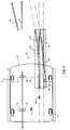
- the conveying system shown in Figure 1 comprises a first rail track 1, which comprises a pair of rails 2 and 3 extending parallel to each other.
- a trolley 4 is movable over said rails.
- the trolley 4 is thereby supported by four self-adjusting running wheels 5 ( Figure 4) provided at its bottom side, which roll over the upper surfaces of the rails 2 and 3.
- a guide means 6 is provided between the rails, said guide means being formed by a strip-shaped means extending parallel to the longitudinal direction of the rails. Said strip-shaped means 6 cooperates with two guide means arranged some distance apart in the intended direction of movement of the trolley according to arrow A, which are each formed by a pair of rollers 7, 8 and 9, 10 respectively, and which are rotatable about upwardly extending axes of rotation.
- a conveying system of this type may for example be used at airports for conveying the luggage 12 of air passengers.
- additional rail tracks 13 are connected to the main rail track 1, generally at several points, via which a trolley may for example be guided to a predetermined station so as to deliver the luggage 12.
- Such an additional rail track 13 is again provided with a pair of rails 14 and 15 extending parallel to each other, which correspond with the rails 2 and 3.
- a switch device 16 is provided near the connection of the rail track 13 to the rail track 1 for diverting a trolley from the rail track 1 to the rail track 13.
- the switch device 16 comprises a plate-shaped means 17 arranged between the rails 2 and 3, in which guide grooves 18 and 19 extending parallel to the longitudinal direction of the rails 2 and 3 are provided.
- Guide grooves 20 and 21 respectively provided in the plate 17, which include an angle with the guide grooves 18 and 19, are connected to said grooves 18 and 19 between the ends of said grooves.
- a switch tongue 22 is disposed near the end of the connection of the guide groove 20 to the guide groove 18, said switch tongue at its downstream end, seen in the intended direction of movement of a trolley 4 according to arrow A, being pivotal to and fro in the direction of arrow B, by suitable setting means 22'', about an upwardly extending pivot pin 22'.
- the switch tongue 22 can furthermore pivot from its normal operating position, against the action of a spring, about a substantially horizontally extending pivot pin 23 provided near the upper end of pivot pin 22', for a purpose yet to be described in more detail hereafter.
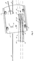
- the trolley is provided with additional guide means, which are formed by cams 24 and 25 secured to the bottom side of the trolley, which cams are connected to the trolley, being freely rotatable about axes of rotation extending perpendicularly.
- cam 25 is thereby arranged some distance before cam 24, seen in the intended direction of movement according to arrow A, whilst cams 24 and 25, seen in the direction of movement according to arrow A, are staggered relative to each other, in a direction transversely to the intended direction of movement according to arrow A.
- the strip-shaped guide means 6 is interrupted, in order to be able to divert trolley 4 from rail means 1 to rail means 13.
- setting means 22'' will move the switch tongue 22 to a position in which the switch tongue 22 releases the access to the guideway 20 and blocks the access to the downstream part of the guide groove 18 located past the switch.
- the front guide cam 25 will be able to move within the guide groove 18 along a certain distance and will subsequently be diverted into the guide groove 20 by the switch tongue 22.
- the front rollers 9 and 10 have already lost contact with the guide strip 6, as will be apparent from Figure 6.
- said trolley 4 is thus guided by cam 25 and the two rollers 7 and 8.
- cam 24 will first move through the upstream part of the guide groove 19 initially, and then be guided into the guide groove 21, whereby the trolley 4 pivots about the axis of the connecting line between rollers or wheels 7 and 8, , as it were, whilst the guide rollers 7 and 8 lose contact with guide means 6, so that at some point of time during the diversion of the trolley from rail track 1 to rail track 13 said trolley 4 is only guided by the two guide rollers 24 and 25 moving through the guide grooves 20 and 21, as is illustrated in Figure 8.
- the cam 25 may run onto the rounded upper edge of the switch tongue, whereby the tongue is pivoted about the pin 23. At some point of time the cam will thereby fall from the rounded upper edge of the tongue, as a result of which jamming of the trolley 4 in question will be prevented.
- a simple switch means may be used for guiding the trolley back from rail track 13 to rail track 1, said switch means being diagrammatically illustrated, more particularly in sectional view, in Figure 10.
- said switch means 27 comprises a plate-shaped part 28, in which guide grooves 29 and 30 being in line with rail track 1 are provided for guiding guide cams of trolleys 4 moved along rail track 1.
- curvilinear guide grooves 31 and 32 are provided, which guide the guide cams 24 and 25 of a trolley coming from rail track 13 when the trolley in question is being diverted from rail track 13 to rail track 1.
Landscapes
- Engineering & Computer Science (AREA)
- Mechanical Engineering (AREA)
- Transportation (AREA)
- Architecture (AREA)
- Civil Engineering (AREA)
- Structural Engineering (AREA)
- Branching, Merging, And Special Transfer Between Conveyors (AREA)
- Intermediate Stations On Conveyors (AREA)
- Control Of Conveyors (AREA)
- Threshing Machine Elements (AREA)
- Platform Screen Doors And Railroad Systems (AREA)
- Non-Mechanical Conveyors (AREA)
- Control Of Vehicles With Linear Motors And Vehicles That Are Magnetically Levitated (AREA)
- Railway Tracks (AREA)
Claims (6)
- Système de transport comprenant un système de rails (1,13) avec un chariot (4) ou analogue, qui est déplaçable le long dudit système de rails (1,13) , et avec un dispositif d'aiguillage (16) au moyen duquel un chariot (4) peut être dévié d'une voie (1) à une autre voie (13) raccordée à ladite première voie (1), dans lequel ledit chariot (4) ou analogue est pourvu de deux éléments de guidage (7,8;9,10) qui sont agencés à une certaine distance l'un de l'autre, dans la direction prévue de mouvement (A) d'un chariot (4) le long d'une voie (1), et qui coopèrent pendant le fonctionnement avec un rail de guidage fixe (6) s'étendant dans la direction longitudinale d'une voie (1), tandis que ledit chariot (4) est pourvu en outre de deux autres éléments de guidage (24,25) qui sont agencés à une certaine distance l'un de l'autre dans la direction prévue de mouvement (A) d'un chariot (4) le long d'une voie (1), caractérisé en ce que lesdits autres éléments de guidage (24,25) sont en outre agencés de façon décalée l'un par rapport à l'autre, transversalement à la direction prévue de mouvement (A), pour coopérer avec des rails de guidage (18-20) et une lame d'aiguillage (22) faisant partie dudit dispositif d'aiguillage (16), pour dévier ledit chariot (4) d'une voie (1) à l'autre (13), de sorte que lesdits rails de guidage (18-21) et ladite lame d'aiguillage (22) sont disposés près du raccordement entre lesdites deux voies (1,13).
- Système de transport selon la revendication 1, caractérisé en ce que le rail de guidage s'étendant dans la direction longitudinale d'une voie est constitué par un élément en forme de bande (6), et les deux éléments de guidage qui coopèrent avec ce dernier comprennent chacun une paire de galets (7,8;9,10) qui sont en contact de part et d'autre dudit élément de guidage en forme de bande (6).
- Système de transport selon la revendication 1 ou 2, caractérisé en ce que ledit dispositif d'aiguillage (16) comporte des rails de guidage (18,19) qui peuvent guider les éléments de guidage (24,25) coopérant avec eux, qui sont connectés audit chariot (4), dans la direction longitudinale de ladite une voie (1), ledit dispositif d'aiguillage comprenant en outre d'autres rails de guidage (20,21), qui définissent un angle avec les premiers rails de guidage (18,19) du dispositif d'aiguillage (16) et au moyen desquels les éléments de guidage (24,25) connectés au chariot (4) peuvent être déviés de façon à dévier le chariot respectif (4) dans la direction d'une autre voie (13).
- Système de transport selon une quelconque des revendications précédentes, caractérisé en ce que les rails de guidage (18-21) faisant partie du dispositif d'aiguillage (16) sont constitués par des rainures, et en ce que les éléments de guidage (24,25) connectés au dit chariot (4), qui coopèrent avec lesdites rainures (18-21), sont constitués par des cames, des tiges ou des roues .
- Système de transport selon la revendication 4, caractérisé en ce qu'une lame d'aiguillage (22) est disposée dans au moins une desdites rainures (18) pour la déviation ou non dudit chariot (4).
- Système de transport selon la revendication 5, caractérisé en ce que ladite lame d'aiguillage (22) peut effectuer un mouvement pivotant autour d'un axe (23) placé près du côté supérieur de ladite lame d'aiguillage (22) et s'étendant transversalement à celle-ci.
Priority Applications (1)
| Application Number | Priority Date | Filing Date | Title |
|---|---|---|---|
| EP97202370A EP0806384A3 (fr) | 1993-12-20 | 1994-12-14 | Système de transport |
Applications Claiming Priority (2)
| Application Number | Priority Date | Filing Date | Title |
|---|---|---|---|
| NL9302211 | 1993-12-20 | ||
| NL9302211A NL9302211A (nl) | 1993-12-20 | 1993-12-20 | Transportinstallatie. |
Related Child Applications (1)
| Application Number | Title | Priority Date | Filing Date |
|---|---|---|---|
| EP97202370A Division EP0806384A3 (fr) | 1993-12-20 | 1994-12-14 | Système de transport |
Publications (2)
| Publication Number | Publication Date |
|---|---|
| EP0659624A1 EP0659624A1 (fr) | 1995-06-28 |
| EP0659624B1 true EP0659624B1 (fr) | 1999-08-11 |
Family
ID=19863282
Family Applications (2)
| Application Number | Title | Priority Date | Filing Date |
|---|---|---|---|
| EP97202370A Withdrawn EP0806384A3 (fr) | 1993-12-20 | 1994-12-14 | Système de transport |
| EP94203618A Expired - Lifetime EP0659624B1 (fr) | 1993-12-20 | 1994-12-14 | Système de transport |
Family Applications Before (1)
| Application Number | Title | Priority Date | Filing Date |
|---|---|---|---|
| EP97202370A Withdrawn EP0806384A3 (fr) | 1993-12-20 | 1994-12-14 | Système de transport |
Country Status (9)
| Country | Link |
|---|---|
| US (1) | US5590995A (fr) |
| EP (2) | EP0806384A3 (fr) |
| JP (1) | JPH0858575A (fr) |
| CN (1) | CN1114629A (fr) |
| AT (1) | ATE183157T1 (fr) |
| CA (1) | CA2138315A1 (fr) |
| DE (1) | DE69420021T2 (fr) |
| DK (1) | DK0659624T3 (fr) |
| NL (1) | NL9302211A (fr) |
Families Citing this family (55)
| Publication number | Priority date | Publication date | Assignee | Title |
|---|---|---|---|---|
| NL1002039C2 (nl) * | 1996-01-08 | 1997-07-09 | Vanderlande Ind Nederland | Transportinrichting. |
| NL1003975C2 (nl) * | 1996-09-06 | 1998-03-09 | Vanderlande Ind Nederland | Inrichting voor het transporteren van voorwerpen. |
| NL1004699C2 (nl) * | 1996-12-05 | 1998-06-08 | Vanderlande Ind Nederland | Transportinrichting. |
| US5990437A (en) * | 1997-02-05 | 1999-11-23 | W & H Systems, Inc. | System for sorting articles |
| US6460681B1 (en) * | 1997-02-05 | 2002-10-08 | W & H Systems | System for sorting articles using a double carrying tray |
| US6011508A (en) * | 1997-10-31 | 2000-01-04 | Magnemotion, Inc. | Accurate position-sensing and communications for guideway operated vehicles |
| DE69827411T2 (de) | 1997-12-12 | 2005-11-10 | Fki Logistex A/S | Förderanlage und verfahren zu deren betrieb |
| NL1007820C2 (nl) | 1997-12-17 | 1999-06-21 | Vanderlande Ind Nederland | Transportinrichting. |
| US6101952A (en) * | 1997-12-24 | 2000-08-15 | Magnemotion, Inc. | Vehicle guidance and switching via magnetic forces |
| NL1009222C2 (nl) * | 1998-05-20 | 1999-11-24 | Vanderlande Ind Nederland | Werkwijze en installatie voor het transporteren van goederen alsmede combinatie van een bak en van een door wielen ondersteund frame voor het transporteren van goederen. |
| NL1010036C2 (nl) * | 1998-09-09 | 2000-03-10 | Vanderlande Ind Nederland | Transportinrichting. |
| US6781524B1 (en) | 2000-03-17 | 2004-08-24 | Magnemotion, Inc. | Passive position-sensing and communications for vehicles on a pathway |
| US20020108839A1 (en) * | 2001-02-09 | 2002-08-15 | Baker Timothy R. | Narrow belt conveyor system |
| US6619473B2 (en) | 2001-07-11 | 2003-09-16 | Rapistan Systems Advertising Corp. | Bolt-up conveyor |
| DE60226503D1 (de) | 2001-09-27 | 2008-06-19 | Fki Logistex As | Tragbehälter für Förderer |
| US6983701B2 (en) * | 2001-10-01 | 2006-01-10 | Magnemotion, Inc. | Suspending, guiding and propelling vehicles using magnetic forces |
| EP1451467B1 (fr) | 2001-10-01 | 2018-02-21 | Magnemotion, Inc. | Conception et fabrication de machines synchrones |
| DE10236168B3 (de) | 2002-08-07 | 2004-03-25 | Siemens Ag | Transportsystem für Stückgutbehälter, insbesondere für Gepäckbehälter |
| EP1452465A1 (fr) | 2003-02-27 | 2004-09-01 | Siemens Aktiengesellschaft | Système de transport pour conteneurs, en particulier pour un système de convoyeur de bagages dans un aéroport |
| DE10315475B4 (de) * | 2003-02-27 | 2006-03-09 | Siemens Ag | Fördersystem für Behälter, insbesondere eine Flughafen-Gepäckförderanlage |
| DE10320963A1 (de) | 2003-05-09 | 2004-12-16 | Siemens Ag | Fördersystem, inbesondere eine Flughafen-Gepäckförderanlage, und eine Entladeeinrichtung eines Fördersystems für Behälter zum Transportieren von Gütern, insbesondere von Gepäckstücken |
| JP4310734B2 (ja) * | 2003-09-08 | 2009-08-12 | 株式会社ダイフク | 摩擦駆動の台車式搬送装置 |
| JP4310733B2 (ja) * | 2003-09-08 | 2009-08-12 | 株式会社ダイフク | 摩擦駆動の台車式搬送装置 |
| KR20070011577A (ko) * | 2004-05-07 | 2007-01-24 | 마그네모션, 인코포레이티드 | 단일 경로를 기반으로 하는 작용기들을 이용한 3차원 동작 |
| DE102004031444A1 (de) | 2004-06-29 | 2006-01-26 | Bosch Rexroth Aktiengesellschaft | Fördervorrichtung mit Weiche bei Übereinanderanordnung der Laufbahnen |
| DE102004031443A1 (de) | 2004-06-29 | 2006-01-26 | Bosch Rexroth Aktiengesellschaft | Fördervorrichtung mit einem Transportwagen mit achsfluchtenden Laufrollen |
| EP1907257A2 (fr) * | 2005-07-22 | 2008-04-09 | Magnemotion, Inc. | Commutation magnetique de vehicules commandee par rail de guidage |
| CN100388455C (zh) * | 2005-09-29 | 2008-05-14 | 中芯国际集成电路制造(上海)有限公司 | 具有安全挡板的晶舟盒导轨传动装置 |
| JP5040271B2 (ja) * | 2006-11-17 | 2012-10-03 | 村田機械株式会社 | 有軌道搬送装置 |
| CZ2008467A3 (cs) * | 2008-07-31 | 2010-02-10 | Dt-Výhybkárna A Strojírna, A. S. | Bloková tramvajová kolejová pulvýmena |
| US8616134B2 (en) | 2009-01-23 | 2013-12-31 | Magnemotion, Inc. | Transport system powered by short block linear synchronous motors |
| US9032880B2 (en) | 2009-01-23 | 2015-05-19 | Magnemotion, Inc. | Transport system powered by short block linear synchronous motors and switching mechanism |
| DE102009014251B4 (de) * | 2009-03-20 | 2010-12-30 | Siemens Aktiengesellschaft | Behälterförderanlage zum Transportieren von Stückgütern, insbesondere von Gepäckstücken |
| JP5077399B2 (ja) * | 2010-07-30 | 2012-11-21 | トヨタ自動車株式会社 | 台車式搬送装置 |
| US9090415B2 (en) * | 2012-09-05 | 2015-07-28 | General Electric Company | System and method for rolling a vehicle to unload cargo |
| US9802507B2 (en) | 2013-09-21 | 2017-10-31 | Magnemotion, Inc. | Linear motor transport for packaging and other uses |
| CN105080846B (zh) * | 2015-06-15 | 2018-01-02 | 河南科技大学 | 一种轨道装置及使用该轨道装置的物流分拣装置 |
| CN104986161B (zh) * | 2015-07-19 | 2018-01-26 | 信发集团有限公司 | 电石输送列车 |
| DE102015218396A1 (de) | 2015-09-24 | 2017-03-30 | Gebr. Willach Gmbh | Förderkette für eine Warenübergabevorrichtung eines automatischen Warenlagers |
| CN106672569A (zh) * | 2016-11-28 | 2017-05-17 | 哈工大机器人集团上海有限公司 | 一种送餐装置 |
| CN106429276A (zh) * | 2016-12-05 | 2017-02-22 | 无锡润和机电技术有限公司 | 筒式原纸用回转小车地轨系统 |
| US10384879B2 (en) | 2017-05-03 | 2019-08-20 | Dematic Corp. | Conveyor belt drive system and configuration |
| CA3073518A1 (fr) * | 2017-09-13 | 2019-03-21 | Laitram, L.L.C. | Transporteur a plateaux monorail a rails de guidage passifs |
| CN108163512A (zh) * | 2017-12-31 | 2018-06-15 | 嘉兴君屹工程有限公司 | 一种l型滑台 |
| CN108657810B (zh) * | 2018-07-03 | 2024-03-26 | 东莞市运泰自动化科技有限公司 | 一种产品与料盒分离机 |
| DE102018121083A1 (de) * | 2018-08-29 | 2020-03-05 | Deutsche Post Ag | Verfahren zum Entladen von Packstücken aus einem gekippten Behälter auf ein Förderband |
| CN109399165B (zh) * | 2018-12-22 | 2024-03-19 | 湖南宏碧园食品有限公司 | 一种食品加工用的输送线转换系统 |
| CN109748055B (zh) * | 2019-03-14 | 2024-01-26 | 重庆大学 | 有向磁性轨道布置结构 |
| US11962214B2 (en) * | 2019-05-28 | 2024-04-16 | B&R Industrial Automation GmbH | Transport device |
| CN110255158B (zh) * | 2019-07-03 | 2024-03-29 | 佛山市蓝箭电子股份有限公司 | 半导体封装粘片设备的翻转上料装置 |
| CN110641942A (zh) * | 2019-11-14 | 2020-01-03 | 民航成都物流技术有限公司 | 一种用于行李处理的高速小车轨道系统 |
| CN111252438A (zh) * | 2020-03-24 | 2020-06-09 | 杭州迅蚁网络科技有限公司 | 一种自动化仓储系统 |
| CN111891142B (zh) * | 2020-09-03 | 2024-06-25 | 山西中科智能控制技术研究院有限公司 | 一种磁牵引行走装置 |
| CN114985272B (zh) * | 2022-06-01 | 2023-07-07 | 港宏机械工程(南京)有限公司 | 一种物流智能分拣转向装置 |
| CN115339374B (zh) * | 2022-08-29 | 2023-12-15 | 中国电子科技集团公司第十四研究所 | 一种用于产线的自动送料和上料小车及自动送料和上料方法 |
Family Cites Families (31)
| Publication number | Priority date | Publication date | Assignee | Title |
|---|---|---|---|---|
| US282125A (en) * | 1883-07-31 | Car-unloading apparatus | ||
| BE547931A (fr) * | ||||
| US1016570A (en) * | 1911-06-02 | 1912-02-06 | Charles L Lawton | Dump-car. |
| US1135669A (en) * | 1914-05-13 | 1915-04-13 | Hans Culemeyer | Device for unloading trucks or freight-cars by tilting them. |
| US1491060A (en) * | 1922-10-14 | 1924-04-22 | O'toole Edward | Car-dumping apparatus |
| US1716240A (en) * | 1925-09-25 | 1929-06-04 | Postweiler Charles | Apparatus for the unloading of railroad cars and other vehicles |
| US2290844A (en) * | 1940-04-20 | 1942-07-21 | Lionel Corp | Unloading toy vehicle and operating device for the same |
| DE1051895B (de) * | 1953-02-13 | 1959-03-05 | Jakob Huber Dr Ing | Einrichtung an Gleisanlagen fuer Schienenfahrzeuge |
| US3013499A (en) * | 1957-05-06 | 1961-12-19 | Cie Francaise De L Afrique Occ | Conveyer systems |
| GB1137099A (en) * | 1966-11-29 | 1968-12-18 | Sovex Ltd | Improvements relating to sorting conveyors |
| US3463298A (en) * | 1967-05-16 | 1969-08-26 | Spra Con Co The | Tray constructions for conveyors |
| US3752334A (en) * | 1971-11-18 | 1973-08-14 | Dravo Corp | Industrial bulk material transportation |
| US3768624A (en) * | 1972-02-11 | 1973-10-30 | Kornylac Co | Elastic belt conveyor |
| US3818839A (en) * | 1972-11-24 | 1974-06-25 | Rexnord Inc | Parallel wheel drive |
| US3880751A (en) * | 1973-12-27 | 1975-04-29 | Speaker Motion Systems | Conveyors with lateral discharge apparatus |
| US3977513A (en) * | 1974-05-28 | 1976-08-31 | Sun Chemical Corporation | Cart conveyor system |
| US3994405A (en) * | 1975-08-26 | 1976-11-30 | Rexnord Inc. | Constant clearance luggage container unloader |
| US4063656A (en) * | 1976-06-24 | 1977-12-20 | Rexnord Inc. | System and apparatus for moving and unloading articles |
| SU992371A1 (ru) * | 1980-06-10 | 1983-01-30 | за вители «С СОЮЗЙДЯ М «ATEffTHoТЕХШ№БС.4Я ««БЛйОЩд | Устройство дл разгрузки сыпучих грузов из бортовых автомобилей |
| US4415303A (en) * | 1981-05-14 | 1983-11-15 | Westendorf Manufacturing Company | Auger wagon |
| SU1025625A1 (ru) * | 1982-04-14 | 1983-06-30 | Dvoryanidov Aleksandr G | Автомобилеразгрузчик |
| AT393819B (de) * | 1983-03-29 | 1991-12-27 | Sticht Fertigungstech Stiwa | Foerdereinrichtung fuer werkstuecke bzw. werkstuecktraeger, insbesondere fuer eine montagemaschine |
| IT1183258B (it) * | 1983-12-02 | 1987-10-22 | Pinfari Srl | Impianto ferroviario a trazione elettrica |
| US4665832A (en) * | 1984-10-22 | 1987-05-19 | Mazda Motor Corporation | Vehicle transfer system |
| IT8520636U1 (it) * | 1985-01-29 | 1986-07-29 | Canziani Francesco | Carrello in particolare per smistatrici a piattelli ribaltabili |
| SE448083B (sv) * | 1985-05-29 | 1987-01-19 | Per Erik Wahren | Transportbana med paletter for transport av tyngre laster |
| JPS63277130A (ja) * | 1987-05-08 | 1988-11-15 | Daifuku Co Ltd | リニアモ−タ−駆動の仕分け用搬送装置 |
| DE3834583A1 (de) * | 1988-10-11 | 1990-04-12 | Rixen Wolfgang | Transportvorrichtung fuer werkstuecke |
| SU1636308A1 (ru) * | 1989-04-11 | 1991-03-23 | Центрально-Черноземный Филиал Всесоюзного Научно-Исследовательского Института Удобрений И Агропочвоведения Им.Д.Н.Прянишникова | Перегрузочно-накопительное устройство |
| DE4210925C2 (de) * | 1992-04-02 | 1994-11-24 | Heinz Nowak | Magnetfahrbahnanlage |
| US5445081A (en) * | 1994-04-13 | 1995-08-29 | Yantrak, Llc | Transit system employing a traction belt |
-
1993
- 1993-12-20 NL NL9302211A patent/NL9302211A/nl not_active Application Discontinuation
-
1994
- 1994-12-14 EP EP97202370A patent/EP0806384A3/fr not_active Withdrawn
- 1994-12-14 EP EP94203618A patent/EP0659624B1/fr not_active Expired - Lifetime
- 1994-12-14 DE DE69420021T patent/DE69420021T2/de not_active Expired - Fee Related
- 1994-12-14 DK DK94203618T patent/DK0659624T3/da active
- 1994-12-14 AT AT94203618T patent/ATE183157T1/de not_active IP Right Cessation
- 1994-12-16 CA CA002138315A patent/CA2138315A1/fr not_active Abandoned
- 1994-12-19 US US08/358,944 patent/US5590995A/en not_active Expired - Fee Related
- 1994-12-19 JP JP6333760A patent/JPH0858575A/ja active Pending
- 1994-12-20 CN CN94120726A patent/CN1114629A/zh active Pending
Also Published As
| Publication number | Publication date |
|---|---|
| ATE183157T1 (de) | 1999-08-15 |
| DK0659624T3 (da) | 1999-12-06 |
| EP0806384A2 (fr) | 1997-11-12 |
| US5590995A (en) | 1997-01-07 |
| DE69420021T2 (de) | 2000-01-20 |
| EP0659624A1 (fr) | 1995-06-28 |
| NL9302211A (nl) | 1995-07-17 |
| EP0806384A3 (fr) | 1998-01-07 |
| CN1114629A (zh) | 1996-01-10 |
| DE69420021D1 (de) | 1999-09-16 |
| JPH0858575A (ja) | 1996-03-05 |
| CA2138315A1 (fr) | 1995-06-21 |
Similar Documents
| Publication | Publication Date | Title |
|---|---|---|
| EP0659624B1 (fr) | Système de transport | |
| US5277124A (en) | Direction control assembly for a material handling car having pivoted divert aims engaging tracks for guidance in switch area | |
| US4732259A (en) | Sorting conveyor with cross-over | |
| US3650216A (en) | Railway car speed control transportation system | |
| CA2147368C (fr) | Convoyeur de tri | |
| EP1210280B1 (fr) | Transfert d'articles entre transporteurs circulant en sens opposes | |
| US5657858A (en) | Conveyor | |
| US5967289A (en) | Electromagnetic switch for diverting objects in high speed conveyors | |
| CN103863811A (zh) | 分类输送机和使物品在转向位置转向的方法 | |
| US4971190A (en) | Conveyor cross switch | |
| EP1097095A1 (fr) | Transporteur | |
| US3811383A (en) | Car switching system | |
| US3799327A (en) | Conveyor system and dog | |
| US5285886A (en) | Conveyor system | |
| US4848533A (en) | Apparatus for conveying panels | |
| JP3404421B2 (ja) | コンベヤ装置及び通路交叉点ピン案内 | |
| EP0742165B1 (fr) | Dispositif pour trier des produits | |
| JP3106141B2 (ja) | トラック交差点におけるピン案内装置、及び、コンベヤ装置 | |
| US5065678A (en) | Conveyor system with transverse pusher to transfer load carrier between seperate conveying paths | |
| US3858626A (en) | Conveyor system | |
| US4148261A (en) | Transfer system for power-and-free conveyor | |
| US2809741A (en) | Edge-wise conveyor system | |
| CN215100353U (zh) | 一种双侧分拣系统 | |
| US3648618A (en) | Subfloor conveyor system and dolly therefor | |
| US5697301A (en) | Suspension type conveyor means |
Legal Events
| Date | Code | Title | Description |
|---|---|---|---|
| PUAI | Public reference made under article 153(3) epc to a published international application that has entered the european phase |
Free format text: ORIGINAL CODE: 0009012 |
|
| AK | Designated contracting states |
Kind code of ref document: A1 Designated state(s): AT BE CH DE DK ES FR GB GR IE IT LI LU MC NL PT SE |
|
| RAX | Requested extension states of the european patent have changed |
Free format text: LT PAYMENT 941214;SI PAYMENT 941214 |
|
| 17P | Request for examination filed |
Effective date: 19951227 |
|
| 17Q | First examination report despatched |
Effective date: 19970131 |
|
| GRAG | Despatch of communication of intention to grant |
Free format text: ORIGINAL CODE: EPIDOS AGRA |
|
| GRAG | Despatch of communication of intention to grant |
Free format text: ORIGINAL CODE: EPIDOS AGRA |
|
| GRAH | Despatch of communication of intention to grant a patent |
Free format text: ORIGINAL CODE: EPIDOS IGRA |
|
| GRAH | Despatch of communication of intention to grant a patent |
Free format text: ORIGINAL CODE: EPIDOS IGRA |
|
| GRAA | (expected) grant |
Free format text: ORIGINAL CODE: 0009210 |
|
| AK | Designated contracting states |
Kind code of ref document: B1 Designated state(s): AT BE CH DE DK ES FR GB GR IE IT LI LU MC NL PT SE |
|
| AX | Request for extension of the european patent |
Free format text: LT PAYMENT 19941214;SI PAYMENT 19941214 |
|
| DX | Miscellaneous (deleted) | ||
| LTIE | Lt: invalidation of european patent or patent extension | ||
| PG25 | Lapsed in a contracting state [announced via postgrant information from national office to epo] |
Ref country code: SE Free format text: THE PATENT HAS BEEN ANNULLED BY A DECISION OF A NATIONAL AUTHORITY Effective date: 19990811 Ref country code: NL Free format text: LAPSE BECAUSE OF FAILURE TO SUBMIT A TRANSLATION OF THE DESCRIPTION OR TO PAY THE FEE WITHIN THE PRESCRIBED TIME-LIMIT Effective date: 19990811 Ref country code: LI Free format text: LAPSE BECAUSE OF FAILURE TO SUBMIT A TRANSLATION OF THE DESCRIPTION OR TO PAY THE FEE WITHIN THE PRESCRIBED TIME-LIMIT Effective date: 19990811 Ref country code: IT Free format text: LAPSE BECAUSE OF FAILURE TO SUBMIT A TRANSLATION OF THE DESCRIPTION OR TO PAY THE FEE WITHIN THE PRE;WARNING: LAPSES OF ITALIAN PATENTS WITH EFFECTIVE DATE BEFORE 2007 MAY HAVE OCCURRED AT ANY TIME BEFORE 2007. THE CORRECT EFFECTIVE DATE MAY BE DIFFERENT FROM THE ONE RECORDED.SCRIBED TIME-LIMIT Effective date: 19990811 Ref country code: GR Free format text: LAPSE BECAUSE OF NON-PAYMENT OF DUE FEES Effective date: 19990811 Ref country code: ES Free format text: THE PATENT HAS BEEN ANNULLED BY A DECISION OF A NATIONAL AUTHORITY Effective date: 19990811 Ref country code: CH Free format text: LAPSE BECAUSE OF FAILURE TO SUBMIT A TRANSLATION OF THE DESCRIPTION OR TO PAY THE FEE WITHIN THE PRESCRIBED TIME-LIMIT Effective date: 19990811 Ref country code: BE Free format text: LAPSE BECAUSE OF FAILURE TO SUBMIT A TRANSLATION OF THE DESCRIPTION OR TO PAY THE FEE WITHIN THE PRESCRIBED TIME-LIMIT Effective date: 19990811 Ref country code: AT Free format text: LAPSE BECAUSE OF FAILURE TO SUBMIT A TRANSLATION OF THE DESCRIPTION OR TO PAY THE FEE WITHIN THE PRESCRIBED TIME-LIMIT Effective date: 19990811 |
|
| REF | Corresponds to: |
Ref document number: 183157 Country of ref document: AT Date of ref document: 19990815 Kind code of ref document: T |
|
| REG | Reference to a national code |
Ref country code: CH Ref legal event code: EP |
|
| REF | Corresponds to: |
Ref document number: 69420021 Country of ref document: DE Date of ref document: 19990916 |
|
| ET | Fr: translation filed | ||
| REG | Reference to a national code |
Ref country code: IE Ref legal event code: FG4D |
|
| PG25 | Lapsed in a contracting state [announced via postgrant information from national office to epo] |
Ref country code: PT Free format text: LAPSE BECAUSE OF FAILURE TO SUBMIT A TRANSLATION OF THE DESCRIPTION OR TO PAY THE FEE WITHIN THE PRESCRIBED TIME-LIMIT Effective date: 19991111 |
|
| REG | Reference to a national code |
Ref country code: DK Ref legal event code: T3 |
|
| PG25 | Lapsed in a contracting state [announced via postgrant information from national office to epo] |
Ref country code: LU Free format text: LAPSE BECAUSE OF NON-PAYMENT OF DUE FEES Effective date: 19991214 Ref country code: IE Free format text: LAPSE BECAUSE OF NON-PAYMENT OF DUE FEES Effective date: 19991214 |
|
| NLV1 | Nl: lapsed or annulled due to failure to fulfill the requirements of art. 29p and 29m of the patents act | ||
| REG | Reference to a national code |
Ref country code: CH Ref legal event code: PL |
|
| PLBE | No opposition filed within time limit |
Free format text: ORIGINAL CODE: 0009261 |
|
| STAA | Information on the status of an ep patent application or granted ep patent |
Free format text: STATUS: NO OPPOSITION FILED WITHIN TIME LIMIT |
|
| PG25 | Lapsed in a contracting state [announced via postgrant information from national office to epo] |
Ref country code: MC Free format text: LAPSE BECAUSE OF NON-PAYMENT OF DUE FEES Effective date: 20000630 |
|
| 26N | No opposition filed | ||
| REG | Reference to a national code |
Ref country code: IE Ref legal event code: MM4A |
|
| PGFP | Annual fee paid to national office [announced via postgrant information from national office to epo] |
Ref country code: FR Payment date: 20011030 Year of fee payment: 8 |
|
| PGFP | Annual fee paid to national office [announced via postgrant information from national office to epo] |
Ref country code: GB Payment date: 20011212 Year of fee payment: 8 |
|
| PGFP | Annual fee paid to national office [announced via postgrant information from national office to epo] |
Ref country code: DE Payment date: 20011217 Year of fee payment: 8 |
|
| PGFP | Annual fee paid to national office [announced via postgrant information from national office to epo] |
Ref country code: DK Payment date: 20011218 Year of fee payment: 8 |
|
| REG | Reference to a national code |
Ref country code: GB Ref legal event code: IF02 |
|
| PG25 | Lapsed in a contracting state [announced via postgrant information from national office to epo] |
Ref country code: GB Free format text: LAPSE BECAUSE OF NON-PAYMENT OF DUE FEES Effective date: 20021214 |
|
| PG25 | Lapsed in a contracting state [announced via postgrant information from national office to epo] |
Ref country code: DK Free format text: LAPSE BECAUSE OF NON-PAYMENT OF DUE FEES Effective date: 20030131 |
|
| PG25 | Lapsed in a contracting state [announced via postgrant information from national office to epo] |
Ref country code: DE Free format text: LAPSE BECAUSE OF NON-PAYMENT OF DUE FEES Effective date: 20030701 |
|
| REG | Reference to a national code |
Ref country code: DK Ref legal event code: EBP |
|
| GBPC | Gb: european patent ceased through non-payment of renewal fee |
Effective date: 20021214 |
|
| PG25 | Lapsed in a contracting state [announced via postgrant information from national office to epo] |
Ref country code: FR Free format text: LAPSE BECAUSE OF NON-PAYMENT OF DUE FEES Effective date: 20030901 |
|
| REG | Reference to a national code |
Ref country code: FR Ref legal event code: ST |