EP0659941A1 - Dispositif de battage de pieux adapté à être utilisé dans un tuyau - Google Patents
Dispositif de battage de pieux adapté à être utilisé dans un tuyau Download PDFInfo
- Publication number
- EP0659941A1 EP0659941A1 EP93203598A EP93203598A EP0659941A1 EP 0659941 A1 EP0659941 A1 EP 0659941A1 EP 93203598 A EP93203598 A EP 93203598A EP 93203598 A EP93203598 A EP 93203598A EP 0659941 A1 EP0659941 A1 EP 0659941A1
- Authority
- EP
- European Patent Office
- Prior art keywords
- tube
- piling
- impact cap
- thickened edge
- hammer
- Prior art date
- Legal status (The legal status is an assumption and is not a legal conclusion. Google has not performed a legal analysis and makes no representation as to the accuracy of the status listed.)
- Granted
Links
- 230000000284 resting effect Effects 0.000 claims abstract description 3
- 238000000034 method Methods 0.000 description 3
- 230000002787 reinforcement Effects 0.000 description 2
- 230000015572 biosynthetic process Effects 0.000 description 1
- 230000008878 coupling Effects 0.000 description 1
- 238000010168 coupling process Methods 0.000 description 1
- 238000005859 coupling reaction Methods 0.000 description 1
- 238000013016 damping Methods 0.000 description 1
- 230000000694 effects Effects 0.000 description 1
- 230000007613 environmental effect Effects 0.000 description 1
- 238000004519 manufacturing process Methods 0.000 description 1
- 239000002689 soil Substances 0.000 description 1
Images


Classifications
-
- E—FIXED CONSTRUCTIONS
- E02—HYDRAULIC ENGINEERING; FOUNDATIONS; SOIL SHIFTING
- E02D—FOUNDATIONS; EXCAVATIONS; EMBANKMENTS; UNDERGROUND OR UNDERWATER STRUCTURES
- E02D7/00—Methods or apparatus for placing sheet pile bulkheads, piles, mouldpipes, or other moulds
- E02D7/28—Placing of hollow pipes or mould pipes by means arranged inside the piles or pipes
Definitions
- This invention relates to a piling apparatus for driving a tube closed at the lower end by a base plate into the ground to form a concrete foundation pile, which apparatus comprises a piling hammer with falling weight and an impact cap acting on the tube.
- Such a piling apparatus has been known from practice for many years.
- the piling hammer is positioned on the upper edge of the tube and the tube is driven into the ground to reach the desired depth by means of a falling weight which is controllable in vertical direction. Subsequently, a reinforcement is provided in the tube and the tube is filled with concrete, after which the tube is withdrawn from the ground under vibration, using a vibrator.
- the object of the present invention is to provide a piling apparatus which, in operation, has a substantially lower sound emission remaining below the maximum sound level allowed by law, so that the piling apparatus can also be used in densely populated areas.
- this object is realized by providing a piling apparatus of the above-described type, with the tube, at the lower end thereof in the vicinity of the base plate, being provided with an inwardly thickened edge, while the piling hammer is provided within the tube and has an impact cap resting in a centred position on both the thickened edge and the bottom plate, which piling hammer comprises a self-centring guide device acting on the inner surface of the tube.
- a further analysis of the piling process teaches that 80% of the piling energy is required for overcoming the point resistance of the tube which is closed at the lower end, and 20% for overcoming the friction of the tube surface in the soil.
- the piling tube may be of a considerably thinner and lighter design than in the case where a piling apparatus acts on the upper end of the tube.
- the noise-producing source i.e. the falling weight, disappears below the ground level and only 20% of the piling energy is delivered to the tube, so that a considerably lower sound emission to the environment takes place.
- the self-centring guide device of the piling hammer ensures that the piling energy is always transmitted centrically to the impact cap, also if the tube is to be driven into the ground not truly vertically but at an oblique angle.
- the thickened edge at the lower end of the tube has a trapezoidal section.
- the diverging portion of this thickened edge facilitates the outflow of concrete when the tube is being withdrawn from the ground and has a compacting effect on the concrete located under the thickened edge during the up-and-down tube movement when the tube is being withdrawn.
- a slightly compressible ring is provided between the bottom plate and the end portion of the tube proximal to that bottom plate.
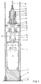
- Fig. 1 shows a piling tube 1, provided, at the lower end thereof, with a base plate 6 closing the piling tube 1, which base plate 6 is fitted loosely over the lower edge of the piling tube 1.
- the piling tube 1 is provided with an inwardly thickened edge 2 of trapezoidal section.
- a complementarily shaped impact cap 3 rests on the converging portion of this edge 2, which impact cap 3 further has a conical shape and rests by its lower face on the bottom of the base plate 6.
- a slightly compressible ring 7 Located between the bottom plate 6 and the end portion of the tube 1 proximal to the bottom plate is a slightly compressible ring 7, ensuring that the impact cap 3 rests both on the converging portion of the thickened edge 2 and on the bottom of the base plate 6.
- the internal piling hammer comprises a guide tube 5 connected to the upper edge of the impact cap 3, which guide tube 5 accommodates a falling weight 4, slidable in vertical direction.
- a self-centring guide device is provided at the upper end of the guide tube 5 comprising a guide bush 11 connected to the guide tube 5, extending in upward direction and having, at the end portion thereof, a threaded part 13 on which a nut/lock nut 17 is provided.
- a slide sleeve 10 can be slid over the guide bush 11, which slide sleeve 10, at the upper end thereof, abuts against a spring 12, whose other end portion abuts against the nut/lock nut 17.
- a ring 16 Located at the lower end of the slide sleeve 10 is a ring 16, also slidable over the guide bush 11 and to which a hair pin-shaped element 15 is connected, to which hair-pin shaped element a hoist cable 14 is attached.
- a set of arms 20 are mounted, evenly distributed along the circumference and pivotally connected to the guide bush 11. These arms 20 carry rollers 9, at the other end pivotally connected to the slide sleeve 10 via arms 21.
- cables 14 are slack
- the slide sleeve 10 is pressed in downward direction by the spring 12, as a result of which the rollers 9 will under pressure abut against the inner wall of the piling tube 1.
- the spring 12 should be dimensioned such that the outward forces acting on the rollers 9 are greater than the laterally directed component of the weight of the piling hammer when the piling tube 1 is oblique, so that in that case, too, the play a between piling tube 1 and guide bush 5 remains present and the piling hammer is in a centred position in the piling tube 1.
- a piston/cylinder combination 22 for operating the falling weight 4, capable of being displaced in upward direction over, for instance, 1 meter and of subsequently falling freely on the impact cap 3.
- the piston/cylinder combination 22 is connected to a pressure line P and also to a return line R. Obviously, the falling weight 4 can also be displaced in upward direction in a different manner.
- the piling hammer is removed from the piling tube 1 as indicated above and the piling tube 1 can internally be provided with a reinforcement, after which the tube can be filled with concrete. Removal of the tube takes place by means of a vibrator, schematically shown in Fig. 3, which is clamped around the upper end of the tube and is capable of bringing the piling tube 1 into a vertically directed oscillating movement. In this connection, it is important that the outflow of concrete 8 at the lower end of the tube is not obstructed by the thickened edge 2.
- this edge 2 facilitates the outflow of the concrete 8 and avoids the formation of a constriction in the concrete foundation pile, which in this manner acquires a diameter D which is at least equal to the diameter of the piling tube.
- the oscillating movement of the piling tube 1, effected by the vibrator provides a thrust action on the concrete 8 that has already left the piling tube 1.
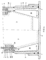
- Fig. 4 shows a second embodiment of the apparatus according to the invention.
- This second embodiment mainly differs from the embodiment shown in Fig. 1 by a different design of the impact cap 3 and the thickened edge of the piling tube 2.
- the thickened edge 2 is of a slightly conical design, as indicated by the dotted line S in Fig. 4, indicating the extension of the inner wall of the piling tube 1.
- the impact cap 3 is of conical design and between the outer wall of the impact cap 3 and the thickened edge 2 a set of wedge-shaped segments 25 are provided, evenly distributed along the circumference of the impact cap 3.
- the piling energy is transmitted via the impact cap 3 to the base plate 6 and via the wedge-shaped segments 25 to the edge 2 of the piling tube 1.
- the segments 25 abut by the outwardly directed teeth thereof against the slightly conical inner face of the thicknened edge 2.
- the segments 25 are coupled to each other by means of two circular springs 19, arranged at the upper and lower ends of the segments 25. These springs 19 keep the segments 25 pressed against the wall of the impact cap 3.
- the outwardly directed edges 18 of the wedge-shaped segments 25 are provided with a rough, hardened surface.
- Fig. 4 further shows a conventional coupling between the guide tube 5 for the falling weight 4 and the impact cap 3.
- the tube 5, at the lower end thereof, is provided with a ring 27, fixedly connected to the tube 5.
- the upper end of the impact cap 3 is provided with a head of a diameter which is approximately equal to the inner diameter of the ring 27.
- a shock-damping ring 28 Positioned between the ring 27 and the impact cap 3 is a shock-damping ring 28, made of rubber.
- the impact cap 3 can move in downward direction relative to the end portion of the tube 5, after which the tube 5 falls on the impact cap 3 with some delay.
- the tube 5 is first displaced in upward direction and subsequently the impact cap 3 is taken along via the bolts 29.
- the wedge-shaped segments are connected to the tube 5 via thin cables and can consequently be taken along as well after the impact cap 3 has been displaced upwards over some distance and the segments 25 have moved radially inwards under the influence of the circular springs 19.
Landscapes
- Engineering & Computer Science (AREA)
- Life Sciences & Earth Sciences (AREA)
- General Life Sciences & Earth Sciences (AREA)
- Mining & Mineral Resources (AREA)
- Paleontology (AREA)
- Civil Engineering (AREA)
- General Engineering & Computer Science (AREA)
- Structural Engineering (AREA)
- Placing Or Removing Of Piles Or Sheet Piles, Or Accessories Thereof (AREA)
Priority Applications (2)
| Application Number | Priority Date | Filing Date | Title |
|---|---|---|---|
| DE1993624695 DE69324695T2 (de) | 1993-12-20 | 1993-12-20 | In einem Rohr anwendbare Pfahlrammvorrichtung |
| EP19930203598 EP0659941B1 (fr) | 1993-12-20 | 1993-12-20 | Dispositif de battage de pieux adapté à être utilisé dans un tuyau |
Applications Claiming Priority (1)
| Application Number | Priority Date | Filing Date | Title |
|---|---|---|---|
| EP19930203598 EP0659941B1 (fr) | 1993-12-20 | 1993-12-20 | Dispositif de battage de pieux adapté à être utilisé dans un tuyau |
Publications (2)
| Publication Number | Publication Date |
|---|---|
| EP0659941A1 true EP0659941A1 (fr) | 1995-06-28 |
| EP0659941B1 EP0659941B1 (fr) | 1999-04-28 |
Family
ID=8214228
Family Applications (1)
| Application Number | Title | Priority Date | Filing Date |
|---|---|---|---|
| EP19930203598 Expired - Lifetime EP0659941B1 (fr) | 1993-12-20 | 1993-12-20 | Dispositif de battage de pieux adapté à être utilisé dans un tuyau |
Country Status (2)
| Country | Link |
|---|---|
| EP (1) | EP0659941B1 (fr) |
| DE (1) | DE69324695T2 (fr) |
Cited By (1)
| Publication number | Priority date | Publication date | Assignee | Title |
|---|---|---|---|---|
| CN114000526A (zh) * | 2021-03-08 | 2022-02-01 | 天津派浦澜能源科技有限公司 | 一种接桩器及使用该接桩器的替打桩 |
Families Citing this family (1)
| Publication number | Priority date | Publication date | Assignee | Title |
|---|---|---|---|---|
| DE102008052724A1 (de) * | 2008-10-22 | 2010-04-29 | Menck Gmbh | Linearführung für den Fallkörper eines Rammhammers |
Citations (6)
| Publication number | Priority date | Publication date | Assignee | Title |
|---|---|---|---|---|
| LU34290A1 (fr) * | ||||
| BE428382A (fr) * | ||||
| GB561765A (en) * | 1943-02-19 | 1944-06-02 | Bell Noel Gonne | Improvements in piles and foundations |
| GB571637A (en) * | 1943-12-29 | 1945-09-03 | Andrew Hood | Improvements in or relating to the manufacture of in situ concrete piles, walls, coffer-dams and the like |
| NL6514594A (fr) * | 1964-12-21 | 1966-06-22 | ||
| CH481277A (fr) * | 1968-07-26 | 1969-11-15 | Rombaldi Albert | Dispositif pour le battage d'un pieu en béton |
-
1993
- 1993-12-20 EP EP19930203598 patent/EP0659941B1/fr not_active Expired - Lifetime
- 1993-12-20 DE DE1993624695 patent/DE69324695T2/de not_active Expired - Fee Related
Patent Citations (6)
| Publication number | Priority date | Publication date | Assignee | Title |
|---|---|---|---|---|
| LU34290A1 (fr) * | ||||
| BE428382A (fr) * | ||||
| GB561765A (en) * | 1943-02-19 | 1944-06-02 | Bell Noel Gonne | Improvements in piles and foundations |
| GB571637A (en) * | 1943-12-29 | 1945-09-03 | Andrew Hood | Improvements in or relating to the manufacture of in situ concrete piles, walls, coffer-dams and the like |
| NL6514594A (fr) * | 1964-12-21 | 1966-06-22 | ||
| CH481277A (fr) * | 1968-07-26 | 1969-11-15 | Rombaldi Albert | Dispositif pour le battage d'un pieu en béton |
Cited By (1)
| Publication number | Priority date | Publication date | Assignee | Title |
|---|---|---|---|---|
| CN114000526A (zh) * | 2021-03-08 | 2022-02-01 | 天津派浦澜能源科技有限公司 | 一种接桩器及使用该接桩器的替打桩 |
Also Published As
| Publication number | Publication date |
|---|---|
| DE69324695D1 (de) | 1999-06-02 |
| DE69324695T2 (de) | 2000-05-04 |
| EP0659941B1 (fr) | 1999-04-28 |
Similar Documents
| Publication | Publication Date | Title |
|---|---|---|
| US5423633A (en) | Piling apparatus adapted to be provided in a tube | |
| US4230425A (en) | Method and installation for producing cast-in-situ piles | |
| US3932999A (en) | Pile driving | |
| NO823193L (no) | Fremgangsmaate og apparat for tildannelse av sandpeler for aa forbedre bloet grunnmasse | |
| EP0659941A1 (fr) | Dispositif de battage de pieux adapté à être utilisé dans un tuyau | |
| GB2286613A (en) | Ground improvement | |
| GB1560900A (en) | Apparatus for use in producing bore holes | |
| US3526283A (en) | Pile driver | |
| US1830651A (en) | Device for the production of piles of concrete and the like | |
| EP4335974B1 (fr) | Procédé d'application d'un profilé dans le souterrain, ainsi que dispositif vibrateur associé | |
| RU2158803C2 (ru) | Установка для вибровдавливания свай в грунт | |
| CN210507399U (zh) | 小型夯扩灰土挤密桩成套设备 | |
| US3356164A (en) | Pile driving mechanisms | |
| CN113187243B (zh) | 一种灌注桩混凝土振动装置 | |
| GB2175033A (en) | In-situ casting of concrete piles | |
| JP2002309575A (ja) | 杭打抜機 | |
| DE594038C (de) | Verfahren und Vorrichtung zur Herstellung von Ortpfaehlen | |
| JP2991569B2 (ja) | ダブルハンマー式杭打ち装置 | |
| JP3209049U (ja) | 杭頭打撃装置 | |
| SU672287A1 (ru) | Устройство дл вытрамбовывани котлованов | |
| CN223753320U (zh) | 一种预制桩桩端载体夯扩装置 | |
| SU939647A1 (ru) | Устройство дл забивки обсадных труб | |
| SU1004597A1 (ru) | Устройство дл образовани скважин в грунте | |
| RU4307U1 (ru) | Устройство для возведения вытрамбованных фундаментов | |
| GB2041049A (en) | Method and Installation for Producing Cast-in-situ Piles |
Legal Events
| Date | Code | Title | Description |
|---|---|---|---|
| PUAI | Public reference made under article 153(3) epc to a published international application that has entered the european phase |
Free format text: ORIGINAL CODE: 0009012 |
|
| AK | Designated contracting states |
Kind code of ref document: A1 Designated state(s): BE CH DE FR GB LI NL |
|
| 17P | Request for examination filed |
Effective date: 19951220 |
|
| 17Q | First examination report despatched |
Effective date: 19971007 |
|
| GRAG | Despatch of communication of intention to grant |
Free format text: ORIGINAL CODE: EPIDOS AGRA |
|
| GRAG | Despatch of communication of intention to grant |
Free format text: ORIGINAL CODE: EPIDOS AGRA |
|
| GRAH | Despatch of communication of intention to grant a patent |
Free format text: ORIGINAL CODE: EPIDOS IGRA |
|
| GRAH | Despatch of communication of intention to grant a patent |
Free format text: ORIGINAL CODE: EPIDOS IGRA |
|
| GRAA | (expected) grant |
Free format text: ORIGINAL CODE: 0009210 |
|
| AK | Designated contracting states |
Kind code of ref document: B1 Designated state(s): BE CH DE FR GB LI NL |
|
| REG | Reference to a national code |
Ref country code: CH Ref legal event code: EP |
|
| REF | Corresponds to: |
Ref document number: 69324695 Country of ref document: DE Date of ref document: 19990602 |
|
| ET | Fr: translation filed | ||
| REG | Reference to a national code |
Ref country code: CH Ref legal event code: NV Representative=s name: E. BLUM & CO. PATENTANWAELTE |
|
| PG25 | Lapsed in a contracting state [announced via postgrant information from national office to epo] |
Ref country code: GB Free format text: LAPSE BECAUSE OF NON-PAYMENT OF DUE FEES Effective date: 19991220 |
|
| PG25 | Lapsed in a contracting state [announced via postgrant information from national office to epo] |
Ref country code: LI Free format text: LAPSE BECAUSE OF NON-PAYMENT OF DUE FEES Effective date: 19991231 Ref country code: CH Free format text: LAPSE BECAUSE OF NON-PAYMENT OF DUE FEES Effective date: 19991231 Ref country code: BE Free format text: LAPSE BECAUSE OF NON-PAYMENT OF DUE FEES Effective date: 19991231 |
|
| PGFP | Annual fee paid to national office [announced via postgrant information from national office to epo] |
Ref country code: NL Payment date: 19991231 Year of fee payment: 7 |
|
| PLBE | No opposition filed within time limit |
Free format text: ORIGINAL CODE: 0009261 |
|
| STAA | Information on the status of an ep patent application or granted ep patent |
Free format text: STATUS: NO OPPOSITION FILED WITHIN TIME LIMIT |
|
| 26N | No opposition filed | ||
| BERE | Be: lapsed |
Owner name: BEHEERSMAATSCHAPPIJ VERSTRAETEN B.V. Effective date: 19991231 |
|
| GBPC | Gb: european patent ceased through non-payment of renewal fee |
Effective date: 19991220 |
|
| PG25 | Lapsed in a contracting state [announced via postgrant information from national office to epo] |
Ref country code: FR Free format text: LAPSE BECAUSE OF NON-PAYMENT OF DUE FEES Effective date: 20000831 |
|
| PG25 | Lapsed in a contracting state [announced via postgrant information from national office to epo] |
Ref country code: DE Free format text: LAPSE BECAUSE OF NON-PAYMENT OF DUE FEES Effective date: 20001003 |
|
| REG | Reference to a national code |
Ref country code: FR Ref legal event code: ST |
|
| PG25 | Lapsed in a contracting state [announced via postgrant information from national office to epo] |
Ref country code: NL Free format text: LAPSE BECAUSE OF NON-PAYMENT OF DUE FEES Effective date: 20010701 |
|
| NLV4 | Nl: lapsed or anulled due to non-payment of the annual fee |
Effective date: 20010701 |