EP0660132A1 - Procédé numérique de détection d'une impulsion courte en temps et dispositif pour sa mise en oeuvre - Google Patents
Procédé numérique de détection d'une impulsion courte en temps et dispositif pour sa mise en oeuvre Download PDFInfo
- Publication number
- EP0660132A1 EP0660132A1 EP94119359A EP94119359A EP0660132A1 EP 0660132 A1 EP0660132 A1 EP 0660132A1 EP 94119359 A EP94119359 A EP 94119359A EP 94119359 A EP94119359 A EP 94119359A EP 0660132 A1 EP0660132 A1 EP 0660132A1
- Authority
- EP
- European Patent Office
- Prior art keywords
- amplitude
- threshold value
- clocked
- under test
- predeterminable
- Prior art date
- Legal status (The legal status is an assumption and is not a legal conclusion. Google has not performed a legal analysis and makes no representation as to the accuracy of the status listed.)
- Withdrawn
Links
Images
Classifications
-
- G—PHYSICS
- G01—MEASURING; TESTING
- G01S—RADIO DIRECTION-FINDING; RADIO NAVIGATION; DETERMINING DISTANCE OR VELOCITY BY USE OF RADIO WAVES; LOCATING OR PRESENCE-DETECTING BY USE OF THE REFLECTION OR RERADIATION OF RADIO WAVES; ANALOGOUS ARRANGEMENTS USING OTHER WAVES
- G01S7/00—Details of systems according to groups G01S13/00, G01S15/00, G01S17/00
- G01S7/02—Details of systems according to groups G01S13/00, G01S15/00, G01S17/00 of systems according to group G01S13/00
- G01S7/28—Details of pulse systems
- G01S7/285—Receivers
- G01S7/292—Extracting wanted echo-signals
- G01S7/2921—Extracting wanted echo-signals based on data belonging to one radar period
- G01S7/2922—Extracting wanted echo-signals based on data belonging to one radar period by using a controlled threshold
Definitions
- the invention is based on a digital method for the detection of short-time pulses according to the preamble of patent claim 1 and an arrangement for carrying out the method according to the preamble of patent claim 5.
- the limit frequency and threshold value can only be changed disadvantageously with a high level of technical complexity, in particular when these values have to be changed over a wide range and quickly over time.
- the invention has for its object to provide a generic method that allows a selection of the pulse lengths of the pulses to be detected within wide limits, further allows simultaneous detection of short pulses of different lengths with one and the same parameterization of the method and that can be carried out inexpensively and reliably.
- the invention is also based on the object of specifying an arrangement for carrying out such a method.
- a first advantage is that the method allows the simultaneous detection of short pulses of different lengths with one and the same setting.
- a second advantage of the invention is that electronic modules and / or assemblies controlled by a clock are used essentially. By changing the clock frequency, an adaptation to the pulse length to be detected is possible in a wide range.
- a third advantage is that otherwise settling times do not occur with a filter, so that a quick change and / or adaptation to changing parameters, e.g. abruptly changing amplitude noise is made possible.
- a fourth advantage is that the threshold value is automatically adapted within wide limits to the changing amplitude values of the noise.
- a fifth advantage is that the circuit arrangement can be implemented with few modules in integrated technology, so that a light, mechanically robust, reliable and inexpensive arrangement is possible.
- the invention is based on a method that uses ordered statistics. Such a method is known from radar technology and is generally used there for so-called CFAR methods ("Constant False Alarm Rate"). Such a method is e.g. known from DE 32 13 430 C2.
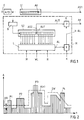
- FIG. 1 shows a schematically illustrated circuit arrangement, a complex analog input signal being present at the input E of an analog / digital converter A / D.
- an associated digitally sampled complex-value input signal which preferably consists of sample values that are equidistant in time.
- the (sampling) clock is selected according to the sampling theorem.
- This digital input signal arrives at a clocked first shift register S1, which has a 10-stage design only for drawing reasons and which only acts as a clocked delay line.
- the first shift register S1 has a so-called signal under test AU in its last memory cell, the tenth stage.
- the complex digital input signal first reaches an absolute value generator B, the output of which is connected to the input of a second shift register S2.
- This is clocked at the same clock rate as the analog / digital converter A / D and the first shift register S1, but has significantly more memory cells, here for example 19.
- the second shift register S2 has its output, the second output AS2, exactly on the memory cell, here the tenth memory cell, as in the first shift register S1.
- the second output AS2 is connected to a first input of a comparator K.
- the signals (amplitudes) stored in the memory cells, with the exception of the output cell (AS2), of the second shift register S2 are sorted in size in a logic circuit L, so that a ranking results.
- a sorting method is described, for example, in German patent DE 32 23 565.
- Each amplitude can thus be assigned a rank in the order, which here comprises 18 ranks, for example.
- the smallest amplitude has rank 1 and the largest amplitude has Rank 18.
- an amplitude signal corresponding to the selected rank for example rank 5 is output at its output AL.
- the output signal (amplitude threshold value) of the multiplier M is fed to a second input of the comparator K.
- This and the output signal AU of the first shift register S1 are present at the outputs AK and AS1 at the same time.
- a pulse to be detected can consist of several samples.
- the signal k ⁇ AL determines an (amplitude) threshold value SW, the temporal course of which is shown in FIG. 2 is shown in dashed lines, which will be explained in more detail below.
- the logic circuit L has further inputs WL and M.
- the number of actually taken into account memory cells in the second shift register S2 can be selected, i.e. a number that is smaller than the maximum number (here: 18) possible memory cells for determining the ranking.
- a (memory cell) window can thus be formed, which can be shifted or thinned with respect to the (output) cell AS2 with the aid of the input M (masking).
- This makes it possible, for example, to lay the window so that the (output) cell AS2 is not in the middle of the window and the cell under Test AUT does not need to be taken into account in the sorting process, for example.
- FIG. 2 shows an exemplary amount input signal which is present at the output of the amount generator B (FIG. 1).
- the amplitude value A is plotted as a function of the number n of the sample value. Since the samples are determined equidistant in time, the abscissa can also be viewed as a time axis.
- the amplitude curve A (n) which is dependent on the digital time n, can be interpreted as a superimposition of noise and / or long-time pulses with short and medium-long pulses P1 to P4, which are to be detected.
- the parameters k, R, WL, M mentioned above and the number of memory cells in the shift registers S1, S2 and the clock frequency used for this are, for example, experimentally adaptable to an expected input signal, for example a radar signal.
- Such a detector for short pulses which is also called SPD (Short Pulse Detector)
- SPD Short Pulse Detector
- Radar technology for target detection short pulse P with variable length
- the invention is not limited to the exemplary embodiment described, but can be applied analogously to others, for example for the detection of short interference pulses but with a variable length (so-called glitches) in a pulse sequence, the (useful) pulses of which are then to be regarded as long pulses.
Landscapes
- Engineering & Computer Science (AREA)
- Radar, Positioning & Navigation (AREA)
- Remote Sensing (AREA)
- Computer Networks & Wireless Communication (AREA)
- Physics & Mathematics (AREA)
- General Physics & Mathematics (AREA)
- Radar Systems Or Details Thereof (AREA)
Applications Claiming Priority (2)
| Application Number | Priority Date | Filing Date | Title |
|---|---|---|---|
| DE4344022A DE4344022C2 (de) | 1993-12-23 | 1993-12-23 | Digitales Verfahren zur Detektion zeitlich kurzer Pulse und Anordnung zur Durchführung des Verfahrens |
| DE4344022 | 1993-12-23 |
Publications (1)
| Publication Number | Publication Date |
|---|---|
| EP0660132A1 true EP0660132A1 (fr) | 1995-06-28 |
Family
ID=6505888
Family Applications (1)
| Application Number | Title | Priority Date | Filing Date |
|---|---|---|---|
| EP94119359A Withdrawn EP0660132A1 (fr) | 1993-12-23 | 1994-12-08 | Procédé numérique de détection d'une impulsion courte en temps et dispositif pour sa mise en oeuvre |
Country Status (4)
| Country | Link |
|---|---|
| US (1) | US5694435A (fr) |
| EP (1) | EP0660132A1 (fr) |
| CA (1) | CA2138927C (fr) |
| DE (1) | DE4344022C2 (fr) |
Families Citing this family (7)
| Publication number | Priority date | Publication date | Assignee | Title |
|---|---|---|---|---|
| DE19545022A1 (de) * | 1995-12-02 | 1997-06-05 | Daimler Benz Aerospace Ag | Digitales Verfahren zur Detektion zeitlich kurzer Pulse und Anordnung zur Durchführung des Verfahrens |
| US5781064A (en) * | 1997-03-18 | 1998-07-14 | Ginjet Technology Corporation | Digital filtering system for filtering digital outputs of a four level FSK demodulator |
| FR2832878B1 (fr) * | 2001-11-27 | 2004-02-13 | Thales Sa | Procede de detection et de traitement de signaux pulses dans un signal radioelectrique |
| US6867728B1 (en) * | 2003-11-06 | 2005-03-15 | Lockheed Martin Corporation | Methods and systems for identifying signals-of-interest |
| EP1566935B1 (fr) * | 2004-02-19 | 2012-07-25 | St Microelectronics S.A. | Dispositif et procédé de suppression d'interférences impulsionnelles dans un signal |
| JP5387211B2 (ja) * | 2009-07-30 | 2014-01-15 | ソニー株式会社 | 線形性改善回路、σδa/d変換器、および受信装置 |
| CN112703420B (zh) * | 2019-04-04 | 2022-06-14 | 华为技术有限公司 | 回波信号的处理方法及装置 |
Citations (4)
| Publication number | Priority date | Publication date | Assignee | Title |
|---|---|---|---|---|
| US4213127A (en) * | 1979-01-31 | 1980-07-15 | The United States Of America As Represented By The Secretary Of The Air Force | Doubly adaptive CFAR apparatus |
| EP0036751A2 (fr) * | 1980-03-24 | 1981-09-30 | The Marconi Company Limited | Détecteur d'évaluation de signal |
| FR2524983A1 (fr) * | 1982-04-10 | 1983-10-14 | Licentia Gmbh | Procede et dispositif d'identification d'objectifs et de suppression de signaux parasites dans les appareils radar |
| WO1990000772A2 (fr) * | 1988-07-15 | 1990-01-25 | Hughes Aircraft Company | Circuit logique pour classement par rang en temps reel |
Family Cites Families (9)
| Publication number | Priority date | Publication date | Assignee | Title |
|---|---|---|---|---|
| GB1377583A (en) * | 1972-01-11 | 1974-12-18 | British Aircraft Corp Ltd | Communication systems |
| US4038540A (en) * | 1976-04-19 | 1977-07-26 | Honeywell Inc. | Quadrature correlation pulse detector |
| DE3213430A1 (de) * | 1982-04-10 | 1983-10-20 | Licentia Patent-Verwaltungs-Gmbh, 6000 Frankfurt | Verfahren und anordnung zur zielerkennung und stoersignalunterdrueckung in radargeraeten |
| DE3223565A1 (de) * | 1982-06-24 | 1983-12-29 | Licentia Patent-Verwaltungs-Gmbh, 6000 Frankfurt | Verfahren und anordnung zur schnellen sortierung der werte einer wertegruppe |
| US4794543A (en) * | 1984-12-24 | 1988-12-27 | Hazeltine Corporation | Multi level split gate signal processor determining the centroid of a signal |
| FR2579038B1 (fr) * | 1985-03-15 | 1987-05-22 | Telecommunications Sa | Perfectionnement aux systemes de reception de messages transmis par modulation en position d'impulsions (ppm) |
| US4972441A (en) * | 1985-10-07 | 1990-11-20 | Honeywell, Inc. | Enhanced pulse time-of-arrival detector |
| US4635277A (en) * | 1985-10-21 | 1987-01-06 | Rockwell International Corporation | Digital clock recovery circuit apparatus |
| GB8613167D0 (en) * | 1986-05-30 | 1986-07-02 | Thorn Emi Datatech Ltd | Circuit |
-
1993
- 1993-12-23 DE DE4344022A patent/DE4344022C2/de not_active Expired - Fee Related
-
1994
- 1994-12-08 EP EP94119359A patent/EP0660132A1/fr not_active Withdrawn
- 1994-12-21 US US08/360,323 patent/US5694435A/en not_active Expired - Lifetime
- 1994-12-22 CA CA002138927A patent/CA2138927C/fr not_active Expired - Fee Related
Patent Citations (4)
| Publication number | Priority date | Publication date | Assignee | Title |
|---|---|---|---|---|
| US4213127A (en) * | 1979-01-31 | 1980-07-15 | The United States Of America As Represented By The Secretary Of The Air Force | Doubly adaptive CFAR apparatus |
| EP0036751A2 (fr) * | 1980-03-24 | 1981-09-30 | The Marconi Company Limited | Détecteur d'évaluation de signal |
| FR2524983A1 (fr) * | 1982-04-10 | 1983-10-14 | Licentia Gmbh | Procede et dispositif d'identification d'objectifs et de suppression de signaux parasites dans les appareils radar |
| WO1990000772A2 (fr) * | 1988-07-15 | 1990-01-25 | Hughes Aircraft Company | Circuit logique pour classement par rang en temps reel |
Also Published As
| Publication number | Publication date |
|---|---|
| DE4344022A1 (de) | 1995-06-29 |
| DE4344022C2 (de) | 2003-06-05 |
| CA2138927C (fr) | 2001-02-06 |
| US5694435A (en) | 1997-12-02 |
| CA2138927A1 (fr) | 1995-06-24 |
Similar Documents
| Publication | Publication Date | Title |
|---|---|---|
| DE2921792A1 (de) | Anordnung zur auffindung der anwesenheit schmaler impulse in einem elektrischen signal | |
| DE1922301B2 (de) | Schaltungsanordnung zum ermitteln von amplitudenaenderungen eines videosignals | |
| DE3427669A1 (de) | Schaltungsanordnung zur verbesserung von signaluebergaengen | |
| EP0660132A1 (fr) | Procédé numérique de détection d'une impulsion courte en temps et dispositif pour sa mise en oeuvre | |
| EP0777130B1 (fr) | Procédé digital de détection d'impulsions courtes et appareil pour la mise en oeuvre du procédé | |
| DE3321263A1 (de) | Puls-doppler-radargeraet mit veraenderbarer pulsfolgefrequenz | |
| DE3337041C1 (de) | Schaltungsvorrichtung zur Logarithmierung und Digitalisierung analoger Signale | |
| DE2600661C3 (de) | Bandkompressionsanordnung | |
| DE2854345C1 (de) | Schaltung zur Festzeichenunterdrückung bei einer Impulsradaranlage | |
| EP0171639A1 (fr) | Dispositif d'élaboration de signaux de cliquetis | |
| EP0942564A2 (fr) | Procedé pour détecter de signaux à impulsions | |
| EP0404237B1 (fr) | Méthode et dispositif de suppression de bruit d'un signal numérique | |
| EP0908735A2 (fr) | Procédé pour déterminer la fréquence d'un signal | |
| EP0026834A2 (fr) | Convertisseur analogique-digital pour l'évaluation du signal de sortie d'un capteur opto-électronique et procédé pour sa mise en oeuvre | |
| EP1345047B1 (fr) | Méthode de traitement de signal et circuit d'évaluation | |
| DE102006040821B4 (de) | Verfahren und Vorrichtung zum Überprüfen von Ausgangssignalen einer integrierten Schaltung | |
| DE2209571C1 (de) | Pulsdopplerradarempfänger mit Entfernungskanälen und mit einer Störungsunterdrückungsschaltung | |
| DE10161602A1 (de) | Verfahren und Anordnung zum graphischen Darstellen der l- und/oder Q-Komponenten von digital modulierten Hochfrequenzsignalen | |
| DE3524021C1 (de) | Adaptiver Signaldetektor | |
| DE10130361A1 (de) | Auswertevorrichtung zum Bewerten eines digitalen Datensignals, insbesondere eines Datensignals für eine Halbleiterspeicherschaltung | |
| EP0463206A1 (fr) | Procédé pour mesurer des petites différences de phase et circuit pour appliquer ce procédé | |
| DE19854608C2 (de) | Zündeinrichtung für Penetratoren | |
| DE2222421C1 (de) | Radarempfaenger mit Filtern und einem Begrenzer zur Stoerungsunterdrueckung | |
| EP0579959A2 (fr) | Dispositif pour la détection d'un signal | |
| DE10005605A1 (de) | Analoge Vorstufe |
Legal Events
| Date | Code | Title | Description |
|---|---|---|---|
| PUAI | Public reference made under article 153(3) epc to a published international application that has entered the european phase |
Free format text: ORIGINAL CODE: 0009012 |
|
| AK | Designated contracting states |
Kind code of ref document: A1 Designated state(s): DE FR GB NL SE |
|
| 17P | Request for examination filed |
Effective date: 19951215 |
|
| 17Q | First examination report despatched |
Effective date: 19980506 |
|
| STAA | Information on the status of an ep patent application or granted ep patent |
Free format text: STATUS: THE APPLICATION IS DEEMED TO BE WITHDRAWN |
|
| 18D | Application deemed to be withdrawn |
Effective date: 19981117 |