EP0660263B1 - Verfahren zum elektrischen Auslesen eines mehrstelligen Rollenzählwerks für ein Volumenmessgerät - Google Patents
Verfahren zum elektrischen Auslesen eines mehrstelligen Rollenzählwerks für ein Volumenmessgerät Download PDFInfo
- Publication number
- EP0660263B1 EP0660263B1 EP94119110A EP94119110A EP0660263B1 EP 0660263 B1 EP0660263 B1 EP 0660263B1 EP 94119110 A EP94119110 A EP 94119110A EP 94119110 A EP94119110 A EP 94119110A EP 0660263 B1 EP0660263 B1 EP 0660263B1
- Authority
- EP
- European Patent Office
- Prior art keywords
- variant
- sensors
- multidigit
- wheel
- segments
- Prior art date
- Legal status (The legal status is an assumption and is not a legal conclusion. Google has not performed a legal analysis and makes no representation as to the accuracy of the status listed.)
- Expired - Lifetime
Links
Images


Classifications
-
- G—PHYSICS
- G01—MEASURING; TESTING
- G01F—MEASURING VOLUME, VOLUME FLOW, MASS FLOW OR LIQUID LEVEL; METERING BY VOLUME
- G01F15/00—Details of, or accessories for, apparatus of groups G01F1/00 - G01F13/00 insofar as such details or appliances are not adapted to particular types of such apparatus
- G01F15/07—Integration to give total flow, e.g. using mechanically-operated integrating mechanism
-
- G—PHYSICS
- G01—MEASURING; TESTING
- G01R—MEASURING ELECTRIC VARIABLES; MEASURING MAGNETIC VARIABLES
- G01R11/00—Electromechanical arrangements for measuring time integral of electric power or current, e.g. of consumption
- G01R11/02—Constructional details
- G01R11/16—Adaptations of counters to electricity meters
-
- G—PHYSICS
- G01—MEASURING; TESTING
- G01D—MEASURING NOT SPECIALLY ADAPTED FOR A SPECIFIC VARIABLE; ARRANGEMENTS FOR MEASURING TWO OR MORE VARIABLES NOT COVERED IN A SINGLE OTHER SUBCLASS; TARIFF METERING APPARATUS; MEASURING OR TESTING NOT OTHERWISE PROVIDED FOR
- G01D5/00—Mechanical means for transferring the output of a sensing member; Means for converting the output of a sensing member to another variable where the form or nature of the sensing member does not constrain the means for converting; Transducers not specially adapted for a specific variable
- G01D5/12—Mechanical means for transferring the output of a sensing member; Means for converting the output of a sensing member to another variable where the form or nature of the sensing member does not constrain the means for converting; Transducers not specially adapted for a specific variable using electric or magnetic means
- G01D5/14—Mechanical means for transferring the output of a sensing member; Means for converting the output of a sensing member to another variable where the form or nature of the sensing member does not constrain the means for converting; Transducers not specially adapted for a specific variable using electric or magnetic means influencing the magnitude of a current or voltage
- G01D5/24—Mechanical means for transferring the output of a sensing member; Means for converting the output of a sensing member to another variable where the form or nature of the sensing member does not constrain the means for converting; Transducers not specially adapted for a specific variable using electric or magnetic means influencing the magnitude of a current or voltage by varying capacitance
- G01D5/241—Mechanical means for transferring the output of a sensing member; Means for converting the output of a sensing member to another variable where the form or nature of the sensing member does not constrain the means for converting; Transducers not specially adapted for a specific variable using electric or magnetic means influencing the magnitude of a current or voltage by varying capacitance by relative movement of capacitor electrodes
- G01D5/2412—Mechanical means for transferring the output of a sensing member; Means for converting the output of a sensing member to another variable where the form or nature of the sensing member does not constrain the means for converting; Transducers not specially adapted for a specific variable using electric or magnetic means influencing the magnitude of a current or voltage by varying capacitance by relative movement of capacitor electrodes by varying overlap
- G01D5/2415—Mechanical means for transferring the output of a sensing member; Means for converting the output of a sensing member to another variable where the form or nature of the sensing member does not constrain the means for converting; Transducers not specially adapted for a specific variable using electric or magnetic means influencing the magnitude of a current or voltage by varying capacitance by relative movement of capacitor electrodes by varying overlap adapted for encoders
-
- G—PHYSICS
- G01—MEASURING; TESTING
- G01D—MEASURING NOT SPECIALLY ADAPTED FOR A SPECIFIC VARIABLE; ARRANGEMENTS FOR MEASURING TWO OR MORE VARIABLES NOT COVERED IN A SINGLE OTHER SUBCLASS; TARIFF METERING APPARATUS; MEASURING OR TESTING NOT OTHERWISE PROVIDED FOR
- G01D5/00—Mechanical means for transferring the output of a sensing member; Means for converting the output of a sensing member to another variable where the form or nature of the sensing member does not constrain the means for converting; Transducers not specially adapted for a specific variable
- G01D5/26—Mechanical means for transferring the output of a sensing member; Means for converting the output of a sensing member to another variable where the form or nature of the sensing member does not constrain the means for converting; Transducers not specially adapted for a specific variable characterised by optical transfer means, i.e. using infrared, visible, or ultraviolet light
- G01D5/32—Mechanical means for transferring the output of a sensing member; Means for converting the output of a sensing member to another variable where the form or nature of the sensing member does not constrain the means for converting; Transducers not specially adapted for a specific variable characterised by optical transfer means, i.e. using infrared, visible, or ultraviolet light with attenuation or whole or partial obturation of beams of light
- G01D5/34—Mechanical means for transferring the output of a sensing member; Means for converting the output of a sensing member to another variable where the form or nature of the sensing member does not constrain the means for converting; Transducers not specially adapted for a specific variable characterised by optical transfer means, i.e. using infrared, visible, or ultraviolet light with attenuation or whole or partial obturation of beams of light the beams of light being detected by photocells
- G01D5/347—Mechanical means for transferring the output of a sensing member; Means for converting the output of a sensing member to another variable where the form or nature of the sensing member does not constrain the means for converting; Transducers not specially adapted for a specific variable characterised by optical transfer means, i.e. using infrared, visible, or ultraviolet light with attenuation or whole or partial obturation of beams of light the beams of light being detected by photocells using displacement encoding scales
- G01D5/34776—Absolute encoders with analogue or digital scales
- G01D5/34792—Absolute encoders with analogue or digital scales with only digital scales or both digital and incremental scales
-
- G—PHYSICS
- G01—MEASURING; TESTING
- G01F—MEASURING VOLUME, VOLUME FLOW, MASS FLOW OR LIQUID LEVEL; METERING BY VOLUME
- G01F15/00—Details of, or accessories for, apparatus of groups G01F1/00 - G01F13/00 insofar as such details or appliances are not adapted to particular types of such apparatus
- G01F15/06—Indicating or recording devices
- G01F15/061—Indicating or recording devices for remote indication
- G01F15/063—Indicating or recording devices for remote indication using electrical means
-
- G—PHYSICS
- G06—COMPUTING OR CALCULATING; COUNTING
- G06M—COUNTING MECHANISMS; COUNTING OF OBJECTS NOT OTHERWISE PROVIDED FOR
- G06M1/00—Design features of general application
- G06M1/27—Design features of general application for representing the result of count in the form of electric signals, e.g. by sensing markings on the counter drum
- G06M1/272—Design features of general application for representing the result of count in the form of electric signals, e.g. by sensing markings on the counter drum using photoelectric means
Definitions
- volume meters for gas and water as well Electricity meter for measuring the flow of energy known in which the measured volume or measured energy with a device adapted to the measuring device Transfer the reduction to a mechanical roller counter becomes.
- the roller counter shows the number since the last one Zero position or that since commissioning flowed through amount of. To determine consumption During a certain period, the status of the Roll counter at the beginning and end of this period read.
- a preferred version for the roller counter consists of an axis on which the number rollers can be rotated are attached and the numbers 0 to 9 on their circumference are applied, and from a second axis with it rotatable pinions such that each smaller number roll in the last tenth of a revolution the next higher value via the assigned shift pinion Scroll forward by one tenth of a turn.
- On Roller counter for a measuring device for water can be found at Example in DE 2 244 404 A1.
- the version of the Measuring device is to achieve a large measuring range important with a good measuring accuracy, which drives the Required torque counter as small as possible hold.
- From US 3 732 404 is a solution for electronic reading known a counter in which the continuous Rotation movement of the number rollers in a snap movement is translated. It must be ensured that the for the snapping movement used spring or similar enough energy picks up one position around the entire roller counter to rotate, for example from 19999 to 20000. From the EP 202722 B1 discloses a solution which uses electronic Readout for a needle type counter using mechanical contacts allowed without snap movement. everyone The above solutions have in common that with them an increase that is required to drive the roller counter Torque is connected.
- US-A-4,031,386 describes the optoelectronic reading of roller counters known, the sensors perpendicular to the number roller axis are arranged.
- the vertical arrangement of a Gray code Sensors to a rotating axis is optoelectronic for a weather measuring device from GB-A-2,130,828 and capacitive for machine elements from CH-A-614,776.
- the present invention is based on the object Display status of a roller counter in a measuring device the simplest possible means at any time digitally read out electronically without having to do so necessary means that drive the roller counter required torque is changed significantly.
- the display status is one mechanical roller counter by means of a suitable, fixed arranged contactless sensors electronically read out, without restricting the rotational movement of the Roll counter such as a snap rotation must be fulfilled.
- a suitable, fixed arranged contactless sensors electronically read out
- the sensors pro Revolution of the roller at least 22 different signal states accept. It is possible to change the angle of rotation of everyone Number roll with an uncertainty of less than 18 ° too measure and the relative position of two adjacent roles with an uncertainty of less than 36 ° and thus the display status of the roller counter reliably determine.
- the sensors take pro 30 different signal states, symmetrical distributed with a rotation angle of the number roll of 12 ° each Signal state. With this solution there is mechanical play from number roll to number roll of up to just under 12 ° permissible, regardless of the number of number roles to be read.
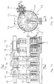
- a first embodiment is in Figure 1a partially cut along line 1a - 1a in Figure 1b and in Figure 1b in cross section along line 1b - 1b in Figure 1a shown.
- Figure 2a shows a second and Figure 2b a third Embodiment.
- Figure 3 shows all possible codes for third embodiment.
- a fourth embodiment is in Figure 4a in view and in Figure 4b in cross section shown.
- Figure 5a shows a fifth embodiment and a sixth exemplary embodiment is shown in FIG. 5b in Partial view and shown in cross section in FIG. 5c.
- the first embodiment works with one-way light barriers, which have optical sensors.
- On a number roll axis 15 are arranged a number of rolls 12, which over Switch pinion 14 are mechanically connected.
- the shift pinion 14 sit on a shift pinion axis 16.
- Die Number rollers 12 are in through an aperture, not shown conventionally visually readable.
- For electronic reading are five light sources on the side of the number rollers 12 10 and on the other hand five sensors or light receivers 11 each with a different radial distance.
- On each number roller 12 is a suitable multi-lane binary code 13 (see Fig. 1b), which consists of translucent and opaque segments (see Figure 1a). This solution poses because of the necessarily small distance of the individual code tracks high demands on accuracy the sensors and the code on the number wheels.
- the Sensors 20 per number roller 12 used as in the first Embodiment are parts of one-way light barriers.
- the Sensors 20 are all on the same sensor print 22 Radial distance on a circular arc around the number roller axis 15 and attached in a radial plane.
- Variants b to k are only for radially symmetrical ones Sensors 30, that is, a distribution with equal angles between the sensors, can be used (see Fig. 2b).
- the codes 21 can also be rotated or mirrored.
- the five sensors 30 are also shown by way of example.
- At One-way light barriers are the segments of the first type Holes formed, the segments of the second type consist of Bridges. It would also be the use of retro-reflective sensors possible, in which case the segments of the first type stand out their reflection properties clearly differ from those of the second type would have to distinguish.
- Design of optical sensors consists of one print 39 arranged parallel to the axis 15 of the number rollers 12 photoelectric elements 40, 41.
- the elements 41 act as Light sources, the light of which is formed by molded light guides 42 is directed to the code-bearing part of the number roller 12 ( Figure 4).
- the elements 40 are optical sensors, e.g. Photoresistors. Place the arrows on the light guides the beam direction of the light.
- FIG. 5a Another inexpensive sensor variant according to a fifth The embodiment is with capacitive sensors 50 equipped ( Figure 5a). Parallel to the number roll is 12 An electrically conductive inner ring 51 with connection 52 near the axis appropriate. The fixed compared to the number rollers 12 Sensors consist of five narrow, among the same Angle spacing arranged with 53 sensor plates electrical connections 54. Inner ring 51 and sensor plate 53 are in a radial plane, preferably on one insulating plate and with a small radial distance to Number roller 12 arranged. The number roller 12 carries one Code disc 55 with three conductive 56 and three not conductive segments 57. To determine the position of a Number roll is the capacity between the inner ring 51 and the individual sensor plates 53 at the connections 52 and 54 measured.
- Figures 5b and 5c show in a sixth Embodiment also with a capacitive variant Radial array sensor 60.
- the Number roller 12 has a side in an annular groove 64 Code cylinder 65 with alternating metallic and non-metallic segments (66, 67). In this case lies the code cylinder 65 is not between sensor plates 63 and Inner ring or cylinder 61, but close enough to the Sensor plate 63 that the measured capacity is sufficient being affected.
Landscapes
- Physics & Mathematics (AREA)
- General Physics & Mathematics (AREA)
- Engineering & Computer Science (AREA)
- Theoretical Computer Science (AREA)
- Power Engineering (AREA)
- Fluid Mechanics (AREA)
- Transmission And Conversion Of Sensor Element Output (AREA)
- Arrangements For Transmission Of Measured Signals (AREA)
- Optical Transform (AREA)
- Rolls And Other Rotary Bodies (AREA)
- Measurement Of Length, Angles, Or The Like Using Electric Or Magnetic Means (AREA)
Description
Claims (7)
- Mehrstelliges Rollenzählwerk für ein Volumenmessgerät für Gas oder Wasser oder für einen Elektrizitätszähler, in welchem von jeweils zwei Zahlenrollen die höherwertige Zahlenrolle von der niederwertigen im letzten Zehntel deren Umdrehung über ein Schaltritzel um eine Zehntelumdrehung weitergedreht wird, und wobei pro auszulesende Zahlenrolle (12) berührungslose Sensoren (11, 20, 30, 50, 60) auf einem Durchmesser in einer Ebene senkrecht zur Zahlenrollenachse (15) angebracht sind, dadurch gekennzeichnet dass auf die Zahlenrollen (12) drei Segmente (31, 56, 66) einer ersten Art mit lichtdurchlässiger oder nichtreflektierender Eigenschaft und drei Segmente (32, 57, 67) einer zweiten Art mit lichtsperrender oder reflektierender Eigenschaft einen, durch Ablesung mittels fünf Sensoren (11, 20, 30, 50, 60), binären Code (13, 21, 55, 65) erzeugend angebracht sind, derart, dass bei einer vollen Umdrehung einer Zahlenrolle (12) mit mindestens einer Variante der Teilungswinkel der Segmenttrennlinien die fünf Sensoren (11, 20, 30, 50, 60) bis zu zweiunddreissig verschiedene Signalzustände erzeugen, wobei die fünf Sensoren (11, 20, 30, 50, 60) als auf einem Print (39) parallel zur Achse (15) der Zahlenrollen (12) angeordnete fotoelektrische Elemente (40, 41) und formgepresste Lichtleiter (42) ausgeführt sind.
- Mehrstelliges Rollenzahlwerk nach Anspruch 1, dadurch gekennzeichnet, dass eine der folgenden Varianten a-k für die Teilungswinkel der Segmenttrennlinien vorhanden ist:Variante a: 18°, 78°, 174°, 198°, 258°, 354°Variante b: 18°, 42°, 78°, 126°, 246°, 354°Variante c: 18°, 42°, 78°, 198°, 318°, 354°Variante d: 18°, 54°, 174°, 258°, 294°, 354°Variante e: 18°, 42°, 150°, 198°, 246°, 354°Variante f: 18°, 54°, 102°, 150°, 258°, 354°Variante g: 18°, 54°, 114°, 150°, 246°, 354°Variante h: 18°, 54°, 150°, 186°, 246°, 354°Variante i: 30°, 78°, 114°, 162°, 270°, 354°Variante k: 30°, 78°, 126°, 162°, 258°, 354°.
- Mehrstelliges Rollenanzeigewerk nach Anspruch 1 oder 2, dadurch gekennzeichnet, dass der Code (13, 21) aus ungleich langen Segmenten (31, 32; 56, 57, 66, 67) besteht, die auf einem Kreisbogen angeordnet sind.
- Mehrstelliges Rollenanzeigewerk nach einem der Ansprüche 1 bis 3 dadurch gekennzeichnet, dass die Sensoren (11, 20, 30, 50, 60) alle auf einem Kreisbogen im gleichen Radialabstand von der Zahlenrollenachse (15) angeordnet sind.
- Mehrstelliges Rollenanzeigewerk nach einem der Ansprüche 1 bis 4 dadurch gekennzeichnet, dass die Sensoren (11, 20, 30) als optische Sensoren, insbesondere Fotodetektoren ausgebildet sind, die Teil einer Einweglichtschranke sind.
- Mehrstelliges Rollenanzeigewerk nach einem der Ansprüche 1 bis 4, dadurch gekennzeichnet, dass die Sensoren (50, 60) als kapazitive Sensoren ausgebildet sind.
- Mehrstelliges Rollenanzeigewerk nach Anspruch 6, dadurch gekennzeichnet, dass die fünf kapazitiven Sensoren (50, 60) als schmale metallisierte Fühlerplättchen (53, 63) ausgebildet sind und sich in der unmittelbaren Nähe der Fühlerplättchen (53, 63) eine Codescheibe (55) oder ein Codezylinder (65) befindet, welche oder welcher abwechselnd metallische (56, 66) und nichtmetallische Segmente (57, 67) aufweist und dass die Kapazität zwischen den Fühlerplättchen (53, 63) und einem elektrisch leitenden Innenring (51, 61) gemessen wird.
Applications Claiming Priority (3)
| Application Number | Priority Date | Filing Date | Title |
|---|---|---|---|
| CH385493 | 1993-12-23 | ||
| CH3854/93 | 1993-12-23 | ||
| CH385493 | 1993-12-23 |
Publications (2)
| Publication Number | Publication Date |
|---|---|
| EP0660263A1 EP0660263A1 (de) | 1995-06-28 |
| EP0660263B1 true EP0660263B1 (de) | 2000-03-01 |
Family
ID=4264910
Family Applications (1)
| Application Number | Title | Priority Date | Filing Date |
|---|---|---|---|
| EP94119110A Expired - Lifetime EP0660263B1 (de) | 1993-12-23 | 1994-12-05 | Verfahren zum elektrischen Auslesen eines mehrstelligen Rollenzählwerks für ein Volumenmessgerät |
Country Status (11)
| Country | Link |
|---|---|
| US (1) | US5565861A (de) |
| EP (1) | EP0660263B1 (de) |
| KR (1) | KR100360511B1 (de) |
| CN (1) | CN1076840C (de) |
| AU (1) | AU678078B2 (de) |
| CA (1) | CA2138888C (de) |
| DE (1) | DE59409167D1 (de) |
| DK (1) | DK0660263T3 (de) |
| ES (1) | ES2145805T3 (de) |
| GR (1) | GR3033532T3 (de) |
| PT (1) | PT660263E (de) |
Cited By (3)
| Publication number | Priority date | Publication date | Assignee | Title |
|---|---|---|---|---|
| EP1965180A1 (de) | 2007-02-09 | 2008-09-03 | GWF MessSysteme AG | Verfahren zur Erkennung einer äusseren Einwirkung auf ein Zählwerk eines Zählers für ein strömendes Medium sowie ein solcher Zähler |
| EP2023096A1 (de) | 2007-08-09 | 2009-02-11 | GWF MessSysteme AG | Messgerät mit einer Plombierung und Verfahren zum Plombieren des Messgerätes für ein strömendes Medium |
| EP2581717A1 (de) | 2011-10-11 | 2013-04-17 | GWF MessSysteme AG | Verfahren zur Bestimmung der angezeigten Ziffern von Zahlenrollen eines Rollenzählwerkes |
Families Citing this family (38)
| Publication number | Priority date | Publication date | Assignee | Title |
|---|---|---|---|---|
| US5640007A (en) * | 1995-06-21 | 1997-06-17 | Limitorque Corporation | Optical encoder comprising a plurality of encoder wheels |
| DE59605586D1 (de) * | 1995-11-17 | 2000-08-17 | Kostal Leopold Gmbh & Co Kg | Winkelsensor |
| US5764164A (en) * | 1997-02-07 | 1998-06-09 | Reality Quest Corp. | Ergonomic hand-attachable controller |
| US5796354A (en) * | 1997-02-07 | 1998-08-18 | Reality Quest Corp. | Hand-attachable controller with direction sensing |
| US6465772B1 (en) * | 1997-10-23 | 2002-10-15 | Nsi Corporation | Optical encoder having multiple thumbwheels with integral encoder patterns |
| ES2304186T3 (es) | 1998-02-27 | 2008-09-16 | Mr Engineering Ag | Dispositivo de lectura para un contador de rodillos. |
| EP0939380B1 (de) * | 1998-02-27 | 2008-03-26 | MR Engineering AG | Ausleseeinrichtung für ein Rollenzählwerk |
| DE10006503A1 (de) * | 2000-02-14 | 2001-08-16 | Abb Research Ltd | Radzählwerk |
| US6674371B1 (en) * | 2000-08-18 | 2004-01-06 | Hersey Meter Company | Utility meter remote reader |
| GB2382768B (en) * | 2001-12-06 | 2004-03-03 | Ofquest Ltd | Folding desk |
| GB2414187B (en) * | 2004-05-21 | 2007-03-07 | Bespak Plc | Dispensing apparatus |
| DE102004055745A1 (de) | 2004-11-18 | 2006-06-01 | Krones Ag | Drehwertgeber und Rundläufermaschine |
| WO2007068242A1 (en) * | 2005-12-16 | 2007-06-21 | Flonidan Dc A/S | Method for volumetric measuring of gas and diaphragm gas meter |
| GB0606055D0 (en) * | 2006-03-25 | 2006-05-03 | Scient Generics Ltd | Non-contact wheel encoder |
| GB2452639B (en) * | 2006-04-21 | 2011-08-10 | Flowserve Man Co | Rotary encoder frequency analysis |
| CN102865400B (zh) * | 2006-04-21 | 2014-11-12 | 芙罗服务管理公司 | 阀促动器 |
| CN101473185B (zh) * | 2006-04-21 | 2011-03-16 | 芙罗服务管理公司 | 具有内置式自测试的旋转编码器 |
| GB2448838B (en) | 2006-05-26 | 2009-02-11 | Consort Medical Plc | Improvements in or relating to dispensing apparatus |
| GB0610541D0 (en) | 2006-05-26 | 2006-07-05 | Bespak Plc | Improvements in or relating to dispensing apparatus |
| ES1063614Y (es) * | 2006-07-04 | 2007-02-16 | Eady Jose Manuel Maura | Dispositivo contador perfeccionado |
| CN100549629C (zh) * | 2007-04-04 | 2009-10-14 | 上海元上电子科技有限公司 | 三进制无乱码字轮码盘传感器 |
| CN101319918B (zh) * | 2008-07-22 | 2010-06-02 | 陈健 | 计量表计数器远传直读式编码器 |
| DE102009003976A1 (de) | 2009-01-07 | 2010-07-08 | Hengstler Gmbh | Vorrichtung zur optischen Abtastung der Teilstriche eines mechanischen Rollenzählwerkes |
| CN102261940A (zh) * | 2011-06-01 | 2011-11-30 | 上海城市水资源开发利用国家工程中心有限公司 | 高可靠电直读式仪表计数器 |
| CN102306272B (zh) * | 2011-08-16 | 2013-08-14 | 成都千嘉科技有限公司 | 一种用于计量计数器编码的方法 |
| CN102661425B (zh) * | 2012-03-15 | 2014-06-11 | 沈居富 | 平衡阀调整器及其组成的平衡阀智能调整系统和方法 |
| CN103134562A (zh) * | 2013-02-06 | 2013-06-05 | 杭州权衡科技有限公司 | 一种利用光路直接读取机械计度器的方法 |
| CN103674151A (zh) * | 2013-11-15 | 2014-03-26 | 安徽鸿凌智能仪表科技有限公司 | 一种无源直读式远传水表 |
| US9441998B2 (en) * | 2014-07-21 | 2016-09-13 | Ecolab Usa Inc. | Oval gear meter |
| CN104501896A (zh) * | 2014-11-19 | 2015-04-08 | 湖北泽捷电子科技有限公司 | 光纤直读式水表 |
| CN104501895B (zh) * | 2014-11-19 | 2017-11-28 | 湖北泽捷电子科技有限公司 | 光纤直读式表头 |
| EP3096450A1 (de) * | 2015-05-20 | 2016-11-23 | Aiut Sp. z o.o. | Elektrische schaltung eines schwingungsgenerators |
| CN106372716B (zh) * | 2016-08-30 | 2018-09-04 | 浙江威星智能仪表股份有限公司 | 一种基于字轮计数装置的计数器编码扩展方法 |
| CN106650909B (zh) * | 2017-02-27 | 2023-05-30 | 中冶华天工程技术有限公司 | 封闭壳体式光电型转动拨码计数装置 |
| CN110569955B (zh) * | 2018-06-05 | 2024-06-04 | 金卡智能集团股份有限公司 | 一种基于电容量的字轮位置判断计数装置及计量仪表 |
| CN113884154B (zh) * | 2020-07-03 | 2023-10-31 | 成都秦川物联网科技股份有限公司 | 用于物联网智能燃气表的基于mcu的双路光电采样方法 |
| KR20220000415U (ko) | 2020-08-10 | 2022-02-17 | 김용 | 보일러의 난방수 순환구조 |
| CN112525281A (zh) * | 2020-12-01 | 2021-03-19 | 深圳市千宝通通科技有限公司 | 一种光纤传导编码计数装置、方法及干式智能表头 |
Family Cites Families (7)
| Publication number | Priority date | Publication date | Assignee | Title |
|---|---|---|---|---|
| US3732404A (en) * | 1971-09-20 | 1973-05-08 | Ripley Co Inc | Meter device |
| DE2244404C3 (de) * | 1972-09-09 | 1982-03-25 | E. Wehrle Gmbh, 7743 Furtwangen | Rollenzählwerk für Flüssigkeitszähler |
| US4031386A (en) * | 1976-06-15 | 1977-06-21 | Rockwell International Corporation | Optical transducer encoding apparatus |
| CH614776A5 (en) * | 1977-01-05 | 1979-12-14 | Husqvarna Ab | Arrangement for determining and representing the position of a first term compared with a second term in an n-digit code |
| GB2130828B (en) * | 1982-10-23 | 1986-06-18 | Danjay Designs Limited | Weather monitor |
| DE3310208A1 (de) * | 1983-03-21 | 1984-10-04 | Siemens AG, 1000 Berlin und 8000 München | Ablesevorrichtung fuer den zaehlerstand eines rollenzaehlwerks |
| BE902500A (fr) * | 1985-05-24 | 1985-09-16 | Aquacom Sa | Compteur totalisateur. |
-
1994
- 1994-12-05 DK DK94119110T patent/DK0660263T3/da active
- 1994-12-05 ES ES94119110T patent/ES2145805T3/es not_active Expired - Lifetime
- 1994-12-05 EP EP94119110A patent/EP0660263B1/de not_active Expired - Lifetime
- 1994-12-05 DE DE59409167T patent/DE59409167D1/de not_active Expired - Lifetime
- 1994-12-05 PT PT94119110T patent/PT660263E/pt unknown
- 1994-12-06 US US08/354,039 patent/US5565861A/en not_active Expired - Lifetime
- 1994-12-20 CN CN94119546A patent/CN1076840C/zh not_active Expired - Lifetime
- 1994-12-21 AU AU81641/94A patent/AU678078B2/en not_active Expired
- 1994-12-21 KR KR1019940035710A patent/KR100360511B1/ko not_active Expired - Lifetime
- 1994-12-22 CA CA002138888A patent/CA2138888C/en not_active Expired - Lifetime
-
2000
- 2000-05-30 GR GR20000401224T patent/GR3033532T3/el not_active IP Right Cessation
Cited By (4)
| Publication number | Priority date | Publication date | Assignee | Title |
|---|---|---|---|---|
| EP1965180A1 (de) | 2007-02-09 | 2008-09-03 | GWF MessSysteme AG | Verfahren zur Erkennung einer äusseren Einwirkung auf ein Zählwerk eines Zählers für ein strömendes Medium sowie ein solcher Zähler |
| EP2023096A1 (de) | 2007-08-09 | 2009-02-11 | GWF MessSysteme AG | Messgerät mit einer Plombierung und Verfahren zum Plombieren des Messgerätes für ein strömendes Medium |
| EP2581717A1 (de) | 2011-10-11 | 2013-04-17 | GWF MessSysteme AG | Verfahren zur Bestimmung der angezeigten Ziffern von Zahlenrollen eines Rollenzählwerkes |
| WO2013053806A1 (de) | 2011-10-11 | 2013-04-18 | Gwf Messsysteme Ag | Verfahren zur bestimmung der ziffern von zahlenrollen eines mechanischen rollenzählwerkes |
Also Published As
| Publication number | Publication date |
|---|---|
| GR3033532T3 (en) | 2000-09-29 |
| KR950019646A (ko) | 1995-07-24 |
| PT660263E (pt) | 2000-08-31 |
| CA2138888A1 (en) | 1995-06-24 |
| DE59409167D1 (de) | 2000-04-06 |
| DK0660263T3 (da) | 2000-08-14 |
| US5565861A (en) | 1996-10-15 |
| AU8164194A (en) | 1995-06-29 |
| CA2138888C (en) | 2005-03-01 |
| CN1076840C (zh) | 2001-12-26 |
| KR100360511B1 (ko) | 2003-02-25 |
| AU678078B2 (en) | 1997-05-15 |
| CN1127351A (zh) | 1996-07-24 |
| ES2145805T3 (es) | 2000-07-16 |
| EP0660263A1 (de) | 1995-06-28 |
Similar Documents
| Publication | Publication Date | Title |
|---|---|---|
| EP0660263B1 (de) | Verfahren zum elektrischen Auslesen eines mehrstelligen Rollenzählwerks für ein Volumenmessgerät | |
| EP2052218B1 (de) | Optoelektronischer winkelsensor und verfahren zur bestimmung eines drehwinkels um eine achse | |
| DE69209157T2 (de) | Vorrichtung zur Messung eines Drehwinkels | |
| EP0268558B1 (de) | Längen- oder Winkelmesseinrichtung | |
| DE3035012C2 (de) | Einrichtung zur Winkelmessung | |
| DE10238640A1 (de) | Multiturn-Winkelmessgerät | |
| DE102015107908A1 (de) | Vorrichtung zur Messung von Drehwinkeln in Zählwerken und mehrstufigen Drehgebern sowie zugehörige Sensoren | |
| DE112011104918T5 (de) | Optischer Geber | |
| EP1355134A1 (de) | Flüssigkeitsfüllstandsmesser | |
| EP0633545B1 (de) | Mehrstelliges Rollenzählwerk mit Encoder | |
| EP0363620A1 (de) | Photoelektrische Positionsmesseinrichtung | |
| DE3202566C2 (de) | ||
| DE19626654A1 (de) | Multiturn-Drehgeber | |
| DE68906033T2 (de) | Sensoreinrichtung. | |
| DE102009023395B4 (de) | Codescheibe für einen Encoder | |
| EP0660264B1 (de) | Verfahren zum elektrischen Auslesen eines mehrstelligen Rollenzählwerks für ein Volumenmessgerät oder für einen Elektrizitätszähler | |
| DE1774578B2 (de) | Flüssigkeitszähler mit elektn scher Fernübertragung | |
| DE102019207322A1 (de) | Optische Ablesevorrichtung für ein Zeigerinstrument | |
| DE10006503A1 (de) | Radzählwerk | |
| DE2553815C3 (de) | Graycode-Aufnehmer | |
| AT242036B (de) | Registriereinrichtung an einer Aufspulvorrichtung für Garne oder Filme | |
| DE19918313A1 (de) | Winkelsensor | |
| DE19908091A1 (de) | Einrichtung zum Erfassen eines Drehwinkels | |
| EP0939380B1 (de) | Ausleseeinrichtung für ein Rollenzählwerk | |
| EP1688708A2 (de) | Vorrichtung zur Bestimmung eines absoluten Drehwinkels |
Legal Events
| Date | Code | Title | Description |
|---|---|---|---|
| PUAI | Public reference made under article 153(3) epc to a published international application that has entered the european phase |
Free format text: ORIGINAL CODE: 0009012 |
|
| AK | Designated contracting states |
Kind code of ref document: A1 Designated state(s): BE CH DE DK ES FR GB GR IT LI NL PT |
|
| 17P | Request for examination filed |
Effective date: 19951117 |
|
| 17Q | First examination report despatched |
Effective date: 19981013 |
|
| GRAG | Despatch of communication of intention to grant |
Free format text: ORIGINAL CODE: EPIDOS AGRA |
|
| GRAG | Despatch of communication of intention to grant |
Free format text: ORIGINAL CODE: EPIDOS AGRA |
|
| GRAH | Despatch of communication of intention to grant a patent |
Free format text: ORIGINAL CODE: EPIDOS IGRA |
|
| GRAH | Despatch of communication of intention to grant a patent |
Free format text: ORIGINAL CODE: EPIDOS IGRA |
|
| GRAA | (expected) grant |
Free format text: ORIGINAL CODE: 0009210 |
|
| AK | Designated contracting states |
Kind code of ref document: B1 Designated state(s): BE CH DE DK ES FR GB GR IT LI NL PT |
|
| REG | Reference to a national code |
Ref country code: CH Ref legal event code: EP |
|
| REF | Corresponds to: |
Ref document number: 59409167 Country of ref document: DE Date of ref document: 20000406 |
|
| REG | Reference to a national code |
Ref country code: CH Ref legal event code: NV Representative=s name: INVENTIO AKTIENGESELLSCHAFT |
|
| ITF | It: translation for a ep patent filed | ||
| GBT | Gb: translation of ep patent filed (gb section 77(6)(a)/1977) |
Effective date: 20000503 |
|
| ET | Fr: translation filed | ||
| REG | Reference to a national code |
Ref country code: ES Ref legal event code: FG2A Ref document number: 2145805 Country of ref document: ES Kind code of ref document: T3 |
|
| REG | Reference to a national code |
Ref country code: DK Ref legal event code: T3 |
|
| REG | Reference to a national code |
Ref country code: PT Ref legal event code: SC4A Free format text: AVAILABILITY OF NATIONAL TRANSLATION Effective date: 20000529 |
|
| PGFP | Annual fee paid to national office [announced via postgrant information from national office to epo] |
Ref country code: GR Payment date: 20001129 Year of fee payment: 7 |
|
| PLBE | No opposition filed within time limit |
Free format text: ORIGINAL CODE: 0009261 |
|
| STAA | Information on the status of an ep patent application or granted ep patent |
Free format text: STATUS: NO OPPOSITION FILED WITHIN TIME LIMIT |
|
| 26N | No opposition filed | ||
| PG25 | Lapsed in a contracting state [announced via postgrant information from national office to epo] |
Ref country code: GR Free format text: LAPSE BECAUSE OF NON-PAYMENT OF DUE FEES Effective date: 20011231 |
|
| REG | Reference to a national code |
Ref country code: GB Ref legal event code: IF02 |
|
| PGFP | Annual fee paid to national office [announced via postgrant information from national office to epo] |
Ref country code: DK Payment date: 20131219 Year of fee payment: 20 Ref country code: PT Payment date: 20130606 Year of fee payment: 20 Ref country code: GB Payment date: 20131219 Year of fee payment: 20 Ref country code: CH Payment date: 20131219 Year of fee payment: 20 Ref country code: DE Payment date: 20131220 Year of fee payment: 20 |
|
| PGFP | Annual fee paid to national office [announced via postgrant information from national office to epo] |
Ref country code: IT Payment date: 20131217 Year of fee payment: 20 Ref country code: NL Payment date: 20131219 Year of fee payment: 20 Ref country code: ES Payment date: 20131226 Year of fee payment: 20 |
|
| PGFP | Annual fee paid to national office [announced via postgrant information from national office to epo] |
Ref country code: BE Payment date: 20131219 Year of fee payment: 20 |
|
| PGFP | Annual fee paid to national office [announced via postgrant information from national office to epo] |
Ref country code: FR Payment date: 20131220 Year of fee payment: 20 |
|
| REG | Reference to a national code |
Ref country code: DE Ref legal event code: R071 Ref document number: 59409167 Country of ref document: DE |
|
| REG | Reference to a national code |
Ref country code: DK Ref legal event code: EUP Effective date: 20141205 |
|
| REG | Reference to a national code |
Ref country code: CH Ref legal event code: PL Ref country code: PT Ref legal event code: MM4A Free format text: MAXIMUM VALIDITY LIMIT REACHED Effective date: 20141205 |
|
| REG | Reference to a national code |
Ref country code: NL Ref legal event code: V4 Effective date: 20141205 |
|
| REG | Reference to a national code |
Ref country code: GB Ref legal event code: PE20 Expiry date: 20141204 |
|
| PG25 | Lapsed in a contracting state [announced via postgrant information from national office to epo] |
Ref country code: GB Free format text: LAPSE BECAUSE OF EXPIRATION OF PROTECTION Effective date: 20141204 Ref country code: PT Free format text: LAPSE BECAUSE OF EXPIRATION OF PROTECTION Effective date: 20141215 |
|
| REG | Reference to a national code |
Ref country code: ES Ref legal event code: FD2A Effective date: 20150826 |
|
| PG25 | Lapsed in a contracting state [announced via postgrant information from national office to epo] |
Ref country code: ES Free format text: LAPSE BECAUSE OF EXPIRATION OF PROTECTION Effective date: 20141206 |