EP0660312A1 - Objective lens drive device and coil bobbin thereof - Google Patents
Objective lens drive device and coil bobbin thereof Download PDFInfo
- Publication number
- EP0660312A1 EP0660312A1 EP94120336A EP94120336A EP0660312A1 EP 0660312 A1 EP0660312 A1 EP 0660312A1 EP 94120336 A EP94120336 A EP 94120336A EP 94120336 A EP94120336 A EP 94120336A EP 0660312 A1 EP0660312 A1 EP 0660312A1
- Authority
- EP
- European Patent Office
- Prior art keywords
- coil
- objective lens
- coil bobbin
- terminals
- drive device
- Prior art date
- Legal status (The legal status is an assumption and is not a legal conclusion. Google has not performed a legal analysis and makes no representation as to the accuracy of the status listed.)
- Granted
Links
Images





Classifications
-
- G—PHYSICS
- G11—INFORMATION STORAGE
- G11B—INFORMATION STORAGE BASED ON RELATIVE MOVEMENT BETWEEN RECORD CARRIER AND TRANSDUCER
- G11B7/00—Recording or reproducing by optical means, e.g. recording using a thermal beam of optical radiation by modifying optical properties or the physical structure, reproducing using an optical beam at lower power by sensing optical properties; Record carriers therefor
- G11B7/08—Disposition or mounting of heads or light sources relatively to record carriers
-
- G—PHYSICS
- G11—INFORMATION STORAGE
- G11B—INFORMATION STORAGE BASED ON RELATIVE MOVEMENT BETWEEN RECORD CARRIER AND TRANSDUCER
- G11B7/00—Recording or reproducing by optical means, e.g. recording using a thermal beam of optical radiation by modifying optical properties or the physical structure, reproducing using an optical beam at lower power by sensing optical properties; Record carriers therefor
- G11B7/08—Disposition or mounting of heads or light sources relatively to record carriers
- G11B7/09—Disposition or mounting of heads or light sources relatively to record carriers with provision for moving the light beam or focus plane for the purpose of maintaining alignment of the light beam relative to the record carrier during transducing operation, e.g. to compensate for surface irregularities of the latter or for track following
- G11B7/0925—Electromechanical actuators for lens positioning
- G11B7/0935—Details of the moving parts
Definitions
- This invention relates to a coil bobbin and an objective lens drive device, and particularly to a coil bobbin having a plurality of coils and to an objective lens drive device in which this coil bobbin is used.
- Optical recording medium for example optical disc recording and/or reproducing apparatuses perform recording or reproduction of information signals on an optical recording medium by irradiating a light beam from an optical pickup onto the recording medium.
- the light beam emitted by the optical pickup is focussed onto the recording surface of the optical recording medium by an objective lens.
- the objective lens is so driven in a focussing direction and a tracking direction by an objective lens drive device that it follows-up any eccentricity and vertical motion of the optical disc.
- An electromagnetic-drive actuator is used as this objective lens drive device.
- an objective lens drive device is constructed for example as shown in Fig. 1.
- an objective lens drive device 1 has a lens holder 2, a coil bobbin 3, a fixed portion 4, a plurality of supporting members 5, a yoke 6, a permanent magnet 7 and a base 8.
- An objective lens 2a is mounted in one end of the lens holder 2, and the coil bobbin 3 is mounted in the other end.
- the lens holder 2 is supported by the plurality of supporting members 5 movably in a direction parallel to the optical axis of the objective lens 2a, namely the focussing direction Fcs, and in a horizontal direction orthogonal to the optical axis of the objective lens 2a, namely the tracking direction Trk.
- the coil bobbin 3 is formed in a square-shaped having a central through hole and is so fixed in the lens holder 2 that the through hole extends in a direction parallel to the optical axis of the objective lens 2a.
- the coil bobbin 3 has a focussing coil not shown in the drawing wound thereon along the direction of the optical axis of the objective lens 2a and a plurality of tracking coils not shown in the drawing are arranged on one side thereof.
- the tracking coils are composed of lead wires wound in rectangular planar coils.
- the focussing coil and the tracking coils are connected to electricity supply wires not shown in the drawing, and a focussing drive signal and a tracking drive signal are supplied to the respective coils through these electricity supply wires.
- the plurality of supporting members 5 are made of elastic members such as plated springs.
- the plurality of supporting members 5 each have one end fixed to the lens holder 2 and the other end fixed to the fixed portion 4 so that they are mutually parallel. As a result, the plurality of supporting members 5 support the lens holder 2 movably in the focussing direction Fcs and the tracking direction Trk.
- the fixed portion 4 is mounted on the base 8.
- the yoke 6 has mutually opposing yoke portions 6a and 6b and is formed in a cross-sectionally U-shaped.
- a permanent magnet 7 is mounted on one of the yoke portions 6a, 6b. In the construction shown in Fig. 1, the permanent magnet 7 is mounted on the yoke portion 6a and inserted into the through hole of the coil bobbin 3, and the other yoke portion 6b faces the focussing coil and the tracking coils of the coil bobbin 3.
- the base 8 is formed in a platelike and is made of a metallic material, and is provided the yoke 6 on a portion thereof.
- a focussing drive signal and a tracking drive signal are supplied to the focussing coil and the tracking coils through the electricity supply wires not shown. Because as shown in Fig. 1 the focussing coil and the tracking coils are located in a gap between the yoke portion 6b and the magnet 7, the magnetic fields generated from the focussing coil and the tracking coils cross the magnetic flux between the magnet 7 and the yoke portion 6b. As a result, driving forces which move the lens holder 2 in the focussing direction Fcs and the tracking direction Trk is are generated, and the lens holder 2 is moved in the focussing direction Fcs and the tracking direction Trk in accordance with the focussing drive signal and the tracking drive signal.
- the light beam focussed onto the recording surface of the optical disc by the objective lens 2a is so controlled that it follows-up any eccentricity of the optical disc and any vertical motion of the recording surface of the optical disc.
- the end portions of the lead wires of the focussing coil and the tracking coils are severally electrically connected by soldering or the like to terminal portions, not shown, provided on the lens holder 2.
- the coil bobbin 3 the focussing coil and the tracking coils are small, and because the lead wires constituting the focussing coil and the tracking coil are thin, the assembly of connecting the end portions of the lead wires to the lens holder 2 has been complicated and difficult. Also, there have been problems such as that this kind of construction is not suited to machine assembly and cost down cannot be achieved.
- an object of the present invention to provide an objective lens drive device which resolves the above-mentioned problems.
- an objective lens drive device including a lens holder, a plurality of elastic supporting members and a coil bobbin.
- the lens holder holds an objective lens.
- the plurality of elastic supporting members each have one end fixed to the lens holder and another end fixed to a fixed portion.
- the elastic supporting members movably support the lens holder in a direction parallel to the optical axis of the objective lens and in a horizontal direction orthogonal to the optical axis of the objective lens.
- the coil bobbin is wound a focussing coil and at least one tracking coil and provided a plurality of terminals on which are wound the coil ends of said focussing coil and said tracking to project from thereof.
- a coil bobbin including a tubular body, a first coil, at least one second coil and a plurality of terminals.
- the body is formed in a tubular shaped.
- the first coil is wound around the outside surface of the body in the axial direction thereof.
- the second coil has a central opening and arranged on the first coil.
- the terminals are projected from the body and are provided on the upper and lower side axial direction ends of the body.
- the plurality of terminals are severally wound around the end portions of the first and second coils.
- the terminals on which the ends of the coils for generating the driving forces for driving the objective lens are wound being so formed that they project from the coil bobbin on which the coils are wound, the electrical connection work can be carried out easily.
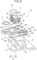
- an objective lens drive device 10 has a lens holder 12, a coil bobbin 13, a plurality of elastic supporting members 14a, 14b, 14c and 14d, a fixing member 16 and a base 15.
- An objective lens 11 is arranged in an opening portion 12e formed in one end, which is a free end, of the lens holder 12, and an opening portion 12c in which the coil bobbin 13 is fixed is formed in the other end.
- the lens holder 12 are composed of an upper holder portion 12a and a lower holder portion 12b molded from a synthetic resin unitedly with the plurality of elastic supporting members 14a, 14b, 14c and 14d as will be described later.
- a notch portion 12d is formed in part of a side face of the opening portion 12c in the lens holder. This notch portion 12d is so formed that at least the whole of a side face of the upper holder portion 12a forming the opening portion 12c is cut away.
- the end portions 14a1, 14b1, 14c1 and 14d1 of the plurality of elastic supporting members 14a, 14b, 14c and 14d project into the notch portion 12d opposite each other, and are electrically connected by soldering as will be described later to terminal portions on the coil bobbin 13.
- the end portions 14b1 and 14d1 are not visible in the drawings.
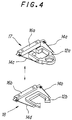
- the lower holder portion 12b has a notch portion corresponding to the objective lens 11 and is formed in substantially U-shaped as shown in Fig. 4.
- the notch portion of the lower holder portion 12b corresponding to the objective lens 11 is possible to pass a light beam emitted from a light source which is not shown to the objective lens 11 and a return beam reflected by the recording medium.
- the objective lens 11 is a single lens of which both faces are an aspherical and made out of glass or an optically transparent synthetic resin.
- the coil bobbin 13 is formed out of synthetic resin or the like in a square pole shape having a central square through hole 13e, as shown in Fig. 6(A), to a size such that it can be inserted into the opening portion 12c in the lens holder 12, and flange portions 13c and 13d are formed at its upper and lower ends respectively.
- the portion between the flange portions 13c and 13d is a winding portion around which is wound a lead wire constituting a focussing coil 13a.
- the focussing coil 13a is wound around the coil bobbin 13 in the direction of the optical axis of the objective lens 11.
- a pair of coil portions constituting a tracking coil 13b are so formed that the planar shape of each is substantially square.
- the pair of coil portions of the tracking coil 13b are mounted on a side face of the focussing coil 13a, and these coil portions are wound consecutively using one lead wire.
- the pair of coil portions of the tracking coil 13b are fixed to one side of the focussing coil 13a as shown in Fig. 3.
- the shape of the coil portions of the tracking coil 13b is not limited to the substantially square shape mentioned above, and any shape having sides parallel to the optical axis of the objective lens 11 will do.
- a plurality of pin-like terminal portions 21a, 21b, 21c and 21d are so provided that they project from the upper and lower flange portions 13c and 13d.
- the distance between the two terminal portions 21a and 21b located at the upper flange portion 13c end is narrower than the distance between the terminal portions 21c and 21d at the lower flange portion 13d end.
- the end portions at the winding starts and the winding ends of the focussing coil 13a and the tracking coil 13b are severally wound around the plurality of terminal portions 21a, 21b, 21c and 21d.
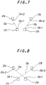
- the winding start 13a-1 of the focussing coil 13a and the winding start 13b-1 of the tracking coil 13b are wound around the terminal portions 21c and 21d respectively
- the winding end 13a-2 of the focussing coil 13a and the winding end 13b-2 of the tracking coil 13b are wound around the terminal portions 21a and 21b respectively.
- Fig. 7 the winding start 13a-1 of the focussing coil 13a and the winding start 13b-1 of the tracking coil 13b are wound around the terminal portions 21c and 21d respectively
- the winding end 13a-2 of the focussing coil 13a and the winding end 13b-2 of the tracking coil 13b are wound around the terminal portions 21a and 21b respectively.
- the winding start 13a-1 of the focussing coil 13a and the winding start 13b-1 of the tracking coil 13b may be wound around the terminal portions 21d and 21c respectively, and the winding end 13a-2 of the focussing coil 13a and the winding end 13b-2 of the tracking coil 13b may be wound around the terminal portions 21a and 21b respectively.
- the winding start and the winding end of the focussing coil 13a cross the winding start and the winding end of the tracking coil 13b.
- the winding start 13a-1 of the focussing coil 13a and the winding start 13b-1 of the tracking coil 13b are doubly wound on the respective terminal portions in order to prevent fraying of the lead wires.
- terminal portions 21a, 21b, 21c and 21d engage with end portions which will be discussed later of the elastic supporting members 14a, 14b, 14c and 14d and are electrically connected thereto by soldering.
- the upper end of the coil bobbin 13 is covered by a cover 24 as shown in Fig. 2.
- the plurality of elastic supporting members 14a, 14b, 14c and 14d are of narrow plate form and are made of an elastic and electrically conductive material for example a metallic material.
- the elastic supporting members 14a, 14b, 14c and 14d each have one end fixed to the lens holder 12 and the other end fixed to the fixing member 16. Because they are narrow in width, these elastic supporting members 14a, 14b, 14c and 14d can displace in both the focussing direction Fcs and the tracking direction Trk.
- the lens holder 12 is supported by these elastic supporting members 14a, 14b, 14c and 14d movably in a direction parallel to the optical axis of the objective lens 11, namely the focussing direction Fcs, and a horizontal direction orthogonal to the optical axis of the objective lens 11, namely the tracking direction Trk.
- the two elastic supporting members 14a and 14c are molded unitedly with the upper holder portion 12a of the lens holder 12 and the upper fixing portion 16a of the fixing member 16 by outsert molding and are so molded that the above-mentioned end portions 14a1 and 14c1 project into the notch portion 12d.
- the portions of the two elastic supporting members 14a and 14c to which the upper holder portion 12a is unitedly molded include arm portions each bent back toward the fixing member 16, as shown with hatching in Fig. 2, and the end portions 14a1 and 14c1 which are electrically connected to the above-mentioned terminal portions 21a and 21b are formed at the ends of these arm portions.
- an upper assembly body 17 The portions of the two elastic supporting members 14a and 14c to which the upper holder portion 12a is unitedly molded.
- the other two elastic supporting members 14b and 14d are formed unitedly with the lower holder portion 12b and the lower fixing portion 16b by an outsert molding method.
- a lower assembly body 18 as shown in Fig. 4.
- the method by which the upper and lower assembly bodies 17 and 18 are manufactured will now be explained more specifically with reference to Fig. 5.
- the two elastic supporting members 14a and 14c with which the upper holder portion 12a is to be unitedly molded are continuously formed in parallel with a first lead frame 19 as shown in Fig. 5 by a punching process.
- the two elastic supporting members 14b and 14d with which the lower holder portion 12b is to be unitedly molded are continuously formed in parallel with a second lead frame 20 as shown in Fig. 5 by a punching process.
- the elastic supporting members 14a, 14b, 14c and 14d formed in the first and second lead frames the first and second lead frames 19 and 20 are each put into and held in an injection molding die.
- Synthetic resin is injected into the dies, an upper holder portion 12a and an upper fixing portion 16a are injection molded onto the first lead frame 19 and a lower holder portion 12b and a lower fixing portion 16b are injection molded onto the second lead frame 20.
- a plurality of upper and lower assembly bodies 17 and 18 are simultaneously molded on the first and second lead frames 19 and 20.
- the upper holder portion 12a and the lower holder portion 12b, and the upper fixing portion 16a and the lower fixing portion 16b, are fixed or joined together by adhesion or an ultrasonic welding method or the like.
- the lens holder 12 is supported by the plurality of elastic supporting members 14a, 14b, 14c and 14d movably in the focussing direction Fcs and the tracking direction Trk.
- the other ends 14a2, 14b2, 14C2 and 14d2 of the elastic supporting members 14a, 14b, 14c and 14d severally project from the rear side of the fixing member 16, and function as terminals through which a focussing drive signal and a tracking drive signal are supplied from a servo circuit not shown.
- the end 14d2 is not visible in the drawings.
- the base 15 is composed of a platelike member made of a rigid material such as metal.
- the base 15 is formed a mounting portion 15a to project from thereof.
- the mounting portion 15a is fixed to the fixing member 16.
- the base 15 further provided a pair of yoke portions 22a and 22b at one end of the base 15.
- the pair of yoke portions 22a and 22b are so provided vertically on the base 15 that they oppose to each other, and a permanent magnet 23 is mounted on one of the yoke portions 22a and 22b, in Fig. 3 the yoke portion 22a.
- a gap of a predetermined width is formed between the yoke portion 22b and the magnet 23, and the focussing coil 13a and the tracking coil 13b are inserted into this gap.
- the base 15 is arranged on the body of an optical pickup device not shown.
- the objective lens 11 is fixed in the opening portions opening portion 12e of the upper holder portion 12a using adhesive or the like, and the coil bobbin 13 is inserted into the opening portion 12c of the lens holder 12, as shown in Fig. 3, of the upper and lower assembly bodies 17 and 18 integrated as described above.
- the coil bobbin 13 can be inserted into the opening portion 12c of the lens holder 12 easily.
- the terminal portions 21a, 21b, 21c and 21d are positioned in the notch portion 12d in the lens holder 12.
- the plurality of terminal portions 21a, 21b, 21c and 21d are then electrically connected by soldering to the end portions 14a1, 14b1, 14c1 and 14d1 of the plurality of elastic supporting members 14a, 14b, 14c and 14d.
- the upper and lower assemblies 17 and 18 are cut from the first and second lead frames 19 and 20 by a cutting apparatus.
- the fixing member 16 is mounted on the mounting portion 15a, whereby the yoke portion 22a and the magnet 23 are inserted into the through hole 13e of the coil bobbin 13 and the focussing coil 13a and the tracking coil 13b are inserted into the gap between the magnet 23 and the yoke portion 22b.
- the focussing coil 13a and the tracking coil 13b oppose to the yoke portion 22b.
- the portions 14a2, 14b2, 14C2 and 14d2 of the plurality of elastic supporting members 14a, 14b, 14c and 14d which project from the fixing member 16 are electrically connected to an external servo circuit and electricity is supplied to the focussing coil 13a and the tracking coil 13b, and the lens holder 12 and the consequently the objective lens 11 are driven in the focussing direction Fcs and the tracking direction Trk.
- one of the assembly bodies 17 and 18 may be cut in advance from the respective lead frame and fixed to the other assembly body, the objective lens 11 and the coil bobbin 13 may be fixed and then finally the other assembly body can be cut from the other lead frame.
- the objective lens 11 and the coil bobbin 13 can be fixed as described above after both the upper and lower assembly bodies 17 and 18 are cut from the first and second lead frames and joined together.
- the objective lens drive device 10 When an objective lens drive device 10 thus constructed is used in a recording and/or reproducing apparatus which uses an optical disc 26 contained a disc cartridge 25 as the recording medium, as shown in Fig. 9, the objective lens drive device 10 is so disposed inside the body of the recording and/or reproducing apparatus that the objective lens 11 oppose to the recording surface of the optical disc 26 through an opening portion 25a of the disc cartridge 25. At this time, the optical axis of the objective lens 11 is perpendicular to the recording surface of the optical disc 26.
- the terminal portions 21a and 21b of the coil bobbin 13 are positioned close to the opening portion 25a and are liable to make contact with the opening portion 25a or portions in the vicinity thereof.
- the terminal portions 21a and 21b are not wound with the winding starts of the focussing coil 13a and the tracking coil 13b but rather are wound with the winding ends of the focussing coil 13a and the tracking coil 13b.
- the reason for this is that because the winding start portions of the focussing coil 13a and the tracking coil 13b are doubly wound in order to prevent fraying of the lead wires, if the winding start portions of the focussing coil 13a and the tracking coil 13b are wound on the terminal portions 21a and 21b the windings on these terminals are thick. As shown in Fig.
- the thickness can be reduced to the thickness indicated in Fig. 9 with the letter L and the terminal portions 21a and 21b making contact with the opening portion 25a or portions in the vicinity thereof can be avoided.
- the plurality of elastic supporting members 14a, 14b, 14c and 14d are so formed unitedly with the upper holder portion 12a and the lower holder portion 12b that the end portions 14a1, 14b1, 14c1 and 14d1 of the elastic supporting members 14a, 14b, 14c and 14d project into the notch portion 12d of the lens holder 12.
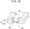
- special supply terminals for supplying electricity to the terminal portions 21a, 21b, 21c and 21d are to be provided, all that is necessary is to provide the lens holder 12 with a plurality of terminal portions 112a, 112b, 112c and 112d unitedly by an insert molding method.
- the end portions of the terminal portions 112b and 112d molded unitedly with the lower holder portion 12b are made longer than the terminal portions 112a and 112c formed unitedly with the upper holder portion 12a by the amount of the hatched portions in Fig. 10.
- the amount by which the terminal portions 112a and 112c project from the upper holder portion 12a is made smaller than the amount by which the terminal portions 112b and 112d project from the lower holder portion 12b.
- the center of gravity of the lens holder 12 moves away from the objective lens 11.
- a balancer for balancing the weight of the movable parts including the lens holder 12 not being necessary resonance during a tracking servo operation and a focussing servo operation of the lens holder 12 can be prevented.
- the winding starts of the focussing coil 13a and the tracking coil 13b be on the lower terminal portions, that is the terminal portions 21c and 21d, because the center of gravity descends by an amount owing to that the lead wires are doubly wound on these terminal portions in order to prevent the lead wires from fraying, and this is beneficial to the weight balance of the objective lens drive device 10.
- the terminal portions 21a, 21b, 21c and 21d were so disposed on the coil bobbin 13 that they were oriented in a direction orthogonal to the tracking direction Trk.
- the terminal portions 21a, 21b, 21c and 21d could be so disposed on the coil bobbin 13 that they are oriented parallel to the tracking direction Trk.
- problems such as that the device contacts with the spindle motor of the recording and/or reproducing apparatus, not shown, which rotationally drives the optical disc 26 occur.
- this invention by so disposing the terminal portions 21a, 21b, 21c and 21d on the coil bobbin 13 that they are oriented in a direction orthogonal to the tracking direction Trk as described above, these kinds of problem can be avoided.
- the terminal portions 21a, 21b, 21c and 21d are so disposed that the distance between the terminal portions 21a and 21b positioned on the flange portion 13c at the upper end of the coil bobbin 13 is narrower than the distance between the two terminal portions 21c and 21d positioned on the flange portions 13d at the lower end.
- the invention is not limited to this configuration, and the terminal portions can for example be configured as shown in Fig. 6(B).
- a coil bobbin 33 is shaped like a square pole having a central square through hole.
- a focussing coil 331 is wound around the coil bobbin 33.
- a tracking coil like that shown in Fig. 6(A) is wound on one side of the coil bobbin 33.
- a plurality of terminal portions 31a, 31b, 31c and 31d are so provided on the side face of the coil bobbin 33 opposite the face on which the tracking coil is wound that they project from the upper and lower portions of the coil bobbin 33.
- These terminal portions 31a, 31b, 31c and 31d when like the coil bobbin 13 shown in Fig. 6(A) the coil bobbin 33 is fixed into the lens holder 12, are electrically connected to the end portions 14a1, 14b1, 14C1 and 14d1 of the plurality of elastic supporting members 14a, 14b, 14c and 14d.
- the terminal portions are so disposed that the spacing between the upper two terminal portions 31a and 31b and the spacing between the lower two terminal portions 31c and 31d are equal.
- the coil bobbin 33 shown in Fig. 6(B) although inferior to the configuration shown in Fig. 6(A) in the ease with which it can be assembled to the lens holder 12, in other respects fulfills the same functions and provides similar benefits to those of the configuration shown in Fig. 6(A).
- an objective lens drive device which drives an objective lens in a focussing direction and a tracking direction was used as an example.
- the invention is not limited to this and can be applied to an objective lens drive device for driving an objective lens in a focussing direction only.
Landscapes
- Optical Recording Or Reproduction (AREA)
Abstract
Description
- This invention relates to a coil bobbin and an objective lens drive device, and particularly to a coil bobbin having a plurality of coils and to an objective lens drive device in which this coil bobbin is used.
- Optical recording medium, for example optical disc recording and/or reproducing apparatuses perform recording or reproduction of information signals on an optical recording medium by irradiating a light beam from an optical pickup onto the recording medium. The light beam emitted by the optical pickup is focussed onto the recording surface of the optical recording medium by an objective lens. The objective lens is so driven in a focussing direction and a tracking direction by an objective lens drive device that it follows-up any eccentricity and vertical motion of the optical disc. An electromagnetic-drive actuator is used as this objective lens drive device.
- An objective lens drive device is constructed for example as shown in Fig. 1. In Fig. 1, an objective
lens drive device 1 has alens holder 2, acoil bobbin 3, afixed portion 4, a plurality of supportingmembers 5, ayoke 6, apermanent magnet 7 and abase 8. - An objective lens 2a is mounted in one end of the
lens holder 2, and thecoil bobbin 3 is mounted in the other end. Thelens holder 2 is supported by the plurality of supportingmembers 5 movably in a direction parallel to the optical axis of the objective lens 2a, namely the focussing direction Fcs, and in a horizontal direction orthogonal to the optical axis of the objective lens 2a, namely the tracking direction Trk. - The
coil bobbin 3 is formed in a square-shaped having a central through hole and is so fixed in thelens holder 2 that the through hole extends in a direction parallel to the optical axis of the objective lens 2a. Thecoil bobbin 3 has a focussing coil not shown in the drawing wound thereon along the direction of the optical axis of the objective lens 2a and a plurality of tracking coils not shown in the drawing are arranged on one side thereof. The tracking coils are composed of lead wires wound in rectangular planar coils. The focussing coil and the tracking coils are connected to electricity supply wires not shown in the drawing, and a focussing drive signal and a tracking drive signal are supplied to the respective coils through these electricity supply wires. The plurality of supportingmembers 5 are made of elastic members such as plated springs. - The plurality of supporting
members 5 each have one end fixed to thelens holder 2 and the other end fixed to thefixed portion 4 so that they are mutually parallel. As a result, the plurality of supportingmembers 5 support thelens holder 2 movably in the focussing direction Fcs and the tracking direction Trk. Thefixed portion 4 is mounted on thebase 8. - The
yoke 6 has mutually opposingyoke portions permanent magnet 7 is mounted on one of theyoke portions permanent magnet 7 is mounted on theyoke portion 6a and inserted into the through hole of thecoil bobbin 3, and theother yoke portion 6b faces the focussing coil and the tracking coils of thecoil bobbin 3. Thebase 8 is formed in a platelike and is made of a metallic material, and is provided theyoke 6 on a portion thereof. - In the objective
lens drive device 1 constructed as described above, a focussing drive signal and a tracking drive signal are supplied to the focussing coil and the tracking coils through the electricity supply wires not shown. Because as shown in Fig. 1 the focussing coil and the tracking coils are located in a gap between theyoke portion 6b and themagnet 7, the magnetic fields generated from the focussing coil and the tracking coils cross the magnetic flux between themagnet 7 and theyoke portion 6b. As a result, driving forces which move thelens holder 2 in the focussing direction Fcs and the tracking direction Trk is are generated, and thelens holder 2 is moved in the focussing direction Fcs and the tracking direction Trk in accordance with the focussing drive signal and the tracking drive signal. The light beam focussed onto the recording surface of the optical disc by the objective lens 2a is so controlled that it follows-up any eccentricity of the optical disc and any vertical motion of the recording surface of the optical disc. - In the objective
lens drive device 1 shown in Fig. 1, the end portions of the lead wires of the focussing coil and the tracking coils are severally electrically connected by soldering or the like to terminal portions, not shown, provided on thelens holder 2. However, because thecoil bobbin 3, the focussing coil and the tracking coils are small, and because the lead wires constituting the focussing coil and the tracking coil are thin, the assembly of connecting the end portions of the lead wires to thelens holder 2 has been complicated and difficult. Also, there have been problems such as that this kind of construction is not suited to machine assembly and cost down cannot be achieved. - Furthermore, after the objective
lens drive device 1 is assembled, continuity checking of the coils and measurement of the magnetic fields generated by the coils are carried out by voltages being impressed across the coil terminals, but in practice it has been difficult to perform coil continuity checking and measurement of the magnetic fields generated by the coils during the assembly process. - It is, therefore, an object of the present invention to provide an objective lens drive device which resolves the above-mentioned problems.
- It is another object of the present invention to provide a coil bobbin which resolves the above-mentioned problems.
- According to the present invention, there is provided an objective lens drive device including a lens holder, a plurality of elastic supporting members and a coil bobbin. The lens holder holds an objective lens. The plurality of elastic supporting members each have one end fixed to the lens holder and another end fixed to a fixed portion. The elastic supporting members movably support the lens holder in a direction parallel to the optical axis of the objective lens and in a horizontal direction orthogonal to the optical axis of the objective lens. The coil bobbin is wound a focussing coil and at least one tracking coil and provided a plurality of terminals on which are wound the coil ends of said focussing coil and said tracking to project from thereof.
- Also, according to the present invention, there is provided a coil bobbin including a tubular body, a first coil, at least one second coil and a plurality of terminals. The body is formed in a tubular shaped. The first coil is wound around the outside surface of the body in the axial direction thereof. The second coil has a central opening and arranged on the first coil. The terminals are projected from the body and are provided on the upper and lower side axial direction ends of the body. The plurality of terminals are severally wound around the end portions of the first and second coils.
- With this invention, by the terminals on which the ends of the coils for generating the driving forces for driving the objective lens are wound being so formed that they project from the coil bobbin on which the coils are wound, the electrical connection work can be carried out easily.
-
- Fig. 1 is a perspective view of an example of an objective lens drive device;
- Fig. 2 is a perspective view of an objective lens drive device according to the invention;
- Fig. 3 is an exploded perspective view of an objective lens drive device according to the invention;
- Fig. 4 is an exploded perspective view of an upper assembly body and a lower assembly body;
- Fig. 5 is a perspective view of upper assembly body and lower assembly body moldings;
- Fig. 6(A) is a perspective view of a coil bobbin used in an objective lens drive device according to the invention, and Fig. 6(B) is a perspective view of another example of a coil bobbin;
- Fig. 7 is a diagram showing an example of a relationship between terminal portions and the winding starts and winding ends of a focussing coil and a tracking coil;
- Fig. 8 is a diagram showing another example of a relationship between terminal portions and the winding starts and winding ends of a focussing coil and a tracking coil;
- Fig. 9 is a main-part sectional view of an objective lens drive device according to the invention used in a recording and/or reproducing apparatus which uses a disc cartridge; and
- Fig. 10 is a perspective view showing an example of an alternative electricity supply terminals configuration.
- An objective lens drive device according to the present invention will now be described in detail with reference to the accompanying drawings.
- As shown in Figs. 2, 3 and 4, an objective
lens drive device 10 has alens holder 12, acoil bobbin 13, a plurality of elastic supportingmembers fixing member 16 and abase 15. - An
objective lens 11 is arranged in anopening portion 12e formed in one end, which is a free end, of thelens holder 12, and anopening portion 12c in which thecoil bobbin 13 is fixed is formed in the other end. Thelens holder 12 are composed of anupper holder portion 12a and alower holder portion 12b molded from a synthetic resin unitedly with the plurality of elastic supportingmembers notch portion 12d is formed in part of a side face of theopening portion 12c in the lens holder. Thisnotch portion 12d is so formed that at least the whole of a side face of theupper holder portion 12a forming theopening portion 12c is cut away. The end portions 14a₁, 14b₁, 14c₁ and 14d₁ of the plurality of elastic supportingmembers notch portion 12d opposite each other, and are electrically connected by soldering as will be described later to terminal portions on thecoil bobbin 13. The end portions 14b₁ and 14d₁ are not visible in the drawings. Thelower holder portion 12b has a notch portion corresponding to theobjective lens 11 and is formed in substantially U-shaped as shown in Fig. 4. The notch portion of thelower holder portion 12b corresponding to theobjective lens 11 is possible to pass a light beam emitted from a light source which is not shown to theobjective lens 11 and a return beam reflected by the recording medium. Theobjective lens 11 is a single lens of which both faces are an aspherical and made out of glass or an optically transparent synthetic resin. - The
coil bobbin 13 is formed out of synthetic resin or the like in a square pole shape having a central square throughhole 13e, as shown in Fig. 6(A), to a size such that it can be inserted into theopening portion 12c in thelens holder 12, andflange portions flange portions coil 13a. The focussingcoil 13a is wound around thecoil bobbin 13 in the direction of the optical axis of theobjective lens 11. A pair of coil portions constituting atracking coil 13b are so formed that the planar shape of each is substantially square. The pair of coil portions of the trackingcoil 13b are mounted on a side face of the focussingcoil 13a, and these coil portions are wound consecutively using one lead wire. The pair of coil portions of the trackingcoil 13b are fixed to one side of the focussingcoil 13a as shown in Fig. 3. The shape of the coil portions of the trackingcoil 13b is not limited to the substantially square shape mentioned above, and any shape having sides parallel to the optical axis of theobjective lens 11 will do. - On the side of the
coil bobbin 13 opposite to that on which thetracking coil 13b is mounted, a plurality of pin-like terminal portions lower flange portions terminal portions upper flange portion 13c end is narrower than the distance between theterminal portions lower flange portion 13d end. - The end portions at the winding starts and the winding ends of the focussing
coil 13a and thetracking coil 13b are severally wound around the plurality ofterminal portions start 13a-1 of the focussingcoil 13a and the winding start 13b-1 of the trackingcoil 13b are wound around theterminal portions end 13a-2 of the focussingcoil 13a and the windingend 13b-2 of the trackingcoil 13b are wound around theterminal portions start 13a-1 of the focussingcoil 13a and the winding start 13b-1 of the trackingcoil 13b may be wound around theterminal portions end 13a-2 of the focussingcoil 13a and the windingend 13b-2 of the trackingcoil 13b may be wound around theterminal portions coil 13a cross the winding start and the winding end of the trackingcoil 13b. The windingstart 13a-1 of the focussingcoil 13a and the winding start 13b-1 of the trackingcoil 13b are doubly wound on the respective terminal portions in order to prevent fraying of the lead wires. - When the
coil bobbin 13 is fixed into thelens holder 12 as described above, theseterminal portions members - The upper end of the
coil bobbin 13 is covered by acover 24 as shown in Fig. 2. - The plurality of elastic supporting
members members lens holder 12 and the other end fixed to the fixingmember 16. Because they are narrow in width, these elastic supportingmembers lens holder 12 is supported by these elastic supportingmembers objective lens 11, namely the focussing direction Fcs, and a horizontal direction orthogonal to the optical axis of theobjective lens 11, namely the tracking direction Trk. The two elastic supportingmembers upper holder portion 12a of thelens holder 12 and theupper fixing portion 16a of the fixingmember 16 by outsert molding and are so molded that the above-mentioned end portions 14a₁ and 14c₁ project into thenotch portion 12d. The portions of the two elastic supportingmembers upper holder portion 12a is unitedly molded include arm portions each bent back toward the fixingmember 16, as shown with hatching in Fig. 2, and the end portions 14a₁ and 14c₁ which are electrically connected to the above-mentionedterminal portions upper assembly body 17. - The other two elastic supporting
members members lower holder portion 12b and thelower fixing portion 16b by an outsert molding method. Thus is formed alower assembly body 18 as shown in Fig. 4. - The method by which the upper and
lower assembly bodies members upper holder portion 12a is to be unitedly molded are continuously formed in parallel with afirst lead frame 19 as shown in Fig. 5 by a punching process. Similarly, the two elastic supportingmembers lower holder portion 12b is to be unitedly molded are continuously formed in parallel with asecond lead frame 20 as shown in Fig. 5 by a punching process. With the elastic supportingmembers upper holder portion 12a and anupper fixing portion 16a are injection molded onto thefirst lead frame 19 and alower holder portion 12b and alower fixing portion 16b are injection molded onto thesecond lead frame 20. As a result, as shown in Fig. 5, a plurality of upper andlower assembly bodies - Before the upper and
lower assembly bodies upper holder portion 12a and thelower holder portion 12b, and theupper fixing portion 16a and thelower fixing portion 16b, are fixed or joined together by adhesion or an ultrasonic welding method or the like. As a result, thelens holder 12 is supported by the plurality of elastic supportingmembers members member 16, and function as terminals through which a focussing drive signal and a tracking drive signal are supplied from a servo circuit not shown. The end 14d₂ is not visible in the drawings. - The
base 15 is composed of a platelike member made of a rigid material such as metal. Thebase 15 is formed a mountingportion 15a to project from thereof. The mountingportion 15a is fixed to the fixingmember 16. The base 15 further provided a pair ofyoke portions base 15. The pair ofyoke portions permanent magnet 23 is mounted on one of theyoke portions yoke portion 22a. A gap of a predetermined width is formed between theyoke portion 22b and themagnet 23, and the focussingcoil 13a and thetracking coil 13b are inserted into this gap. Thebase 15 is arranged on the body of an optical pickup device not shown. - The
objective lens 11 is fixed in the openingportions opening portion 12e of theupper holder portion 12a using adhesive or the like, and thecoil bobbin 13 is inserted into theopening portion 12c of thelens holder 12, as shown in Fig. 3, of the upper andlower assembly bodies terminal portions terminal portions coil bobbin 13 can be inserted into theopening portion 12c of thelens holder 12 easily. When thecoil bobbin 13 is inserted into theopening portion 12c in thelens holder 12, as necessary it is fixed to thelens holder 12 by adhesive or the like. When thecoil bobbin 13 has been inserted into theopening portion 12c of thelens holder 12, theterminal portions notch portion 12d in thelens holder 12. The plurality ofterminal portions members lens holder 12, because the winding starts and the winding ends of the focussingcoil 13a and thetracking coil 13b are severally wound around theterminal portions coil 13a and thetracking coil 13b and measurement of the magnetic fields generated thereby by supplying a voltage between either thefirst lead frame 19 or thesecond lead frame 20 and a holder portion elastic supporting member of either the elastic supportingmembers upper holder portion 12a or the elastic supportingmembers lower holder portion 12b. - After all the connection and assembly work on the
lens holder 12 is finished, the upper andlower assemblies member 16 is mounted on the mountingportion 15a, whereby theyoke portion 22a and themagnet 23 are inserted into the throughhole 13e of thecoil bobbin 13 and the focussingcoil 13a and thetracking coil 13b are inserted into the gap between themagnet 23 and theyoke portion 22b. The focussingcoil 13a and thetracking coil 13b oppose to theyoke portion 22b. The portions 14a₂, 14b₂, 14C₂ and 14d₂ of the plurality of elastic supportingmembers member 16 are electrically connected to an external servo circuit and electricity is supplied to the focussingcoil 13a and thetracking coil 13b, and thelens holder 12 and the consequently theobjective lens 11 are driven in the focussing direction Fcs and the tracking direction Trk. Of course, alternatively one of theassembly bodies objective lens 11 and thecoil bobbin 13 may be fixed and then finally the other assembly body can be cut from the other lead frame. Or, theobjective lens 11 and thecoil bobbin 13 can be fixed as described above after both the upper andlower assembly bodies - When an objective
lens drive device 10 thus constructed is used in a recording and/or reproducing apparatus which uses anoptical disc 26 contained adisc cartridge 25 as the recording medium, as shown in Fig. 9, the objectivelens drive device 10 is so disposed inside the body of the recording and/or reproducing apparatus that theobjective lens 11 oppose to the recording surface of theoptical disc 26 through anopening portion 25a of thedisc cartridge 25. At this time, the optical axis of theobjective lens 11 is perpendicular to the recording surface of theoptical disc 26. Here, theterminal portions coil bobbin 13 are positioned close to theopening portion 25a and are liable to make contact with theopening portion 25a or portions in the vicinity thereof. In order to avoid any such contact between theterminal portions opening portion 25a or portions in the vicinity thereof, theterminal portions coil 13a and thetracking coil 13b but rather are wound with the winding ends of the focussingcoil 13a and thetracking coil 13b. The reason for this is that because the winding start portions of the focussingcoil 13a and thetracking coil 13b are doubly wound in order to prevent fraying of the lead wires, if the winding start portions of the focussingcoil 13a and thetracking coil 13b are wound on theterminal portions coil 13a and thetracking coil 13b on theterminal portions terminal portions opening portion 25a or portions in the vicinity thereof can be avoided. - In the objective
lens drive device 10 described above, the plurality of elastic supportingmembers upper holder portion 12a and thelower holder portion 12b that the end portions 14a₁, 14b₁, 14c₁ and 14d₁ of the elastic supportingmembers notch portion 12d of thelens holder 12. When instead special supply terminals for supplying electricity to theterminal portions lens holder 12 with a plurality ofterminal portions terminal portions lower holder portion 12b are made longer than theterminal portions upper holder portion 12a by the amount of the hatched portions in Fig. 10. In other words, the amount by which theterminal portions upper holder portion 12a is made smaller than the amount by which theterminal portions lower holder portion 12b. As a result, the assembly of inserting thecoil bobbin 13 intoopening portion 12c in thelens holder 12 can be carried out easily. - In the objective
lens drive device 10 described above, because the plurality ofterminal portions lens holder 12 to theobjective lens 11 and project toward the fixingmember 16, the center of gravity of thelens holder 12 moves away from theobjective lens 11. As a result, as well as a balancer for balancing the weight of the movable parts including thelens holder 12 not being necessary, resonance during a tracking servo operation and a focussing servo operation of thelens holder 12 can be prevented. - Also, in winding the focussing
coil 13a and thetracking coil 13b onto thecoil bobbin 13, which of the plurality ofterminal portions coil 13a and thetracking coil 13b be on the lower terminal portions, that is theterminal portions lens drive device 10. - In the example described above, the
terminal portions coil bobbin 13 that they were oriented in a direction orthogonal to the tracking direction Trk. Alternatively theterminal portions coil bobbin 13 that they are oriented parallel to the tracking direction Trk. However, in this case, when an optical pickup device in which this objectivelens drive device 10 is moved toward the inside portion of theoptical disc 26, problems such as that the device contacts with the spindle motor of the recording and/or reproducing apparatus, not shown, which rotationally drives theoptical disc 26 occur. In this invention, by so disposing theterminal portions coil bobbin 13 that they are oriented in a direction orthogonal to the tracking direction Trk as described above, these kinds of problem can be avoided. - In the preferred embodiment described above, as shown in Fig. 6(A), the
terminal portions terminal portions flange portion 13c at the upper end of thecoil bobbin 13 is narrower than the distance between the twoterminal portions flange portions 13d at the lower end. However, the invention is not limited to this configuration, and the terminal portions can for example be configured as shown in Fig. 6(B). In Fig. 6(B), acoil bobbin 33 is shaped like a square pole having a central square through hole. A focussingcoil 331 is wound around thecoil bobbin 33. Although not shown in the drawings, a tracking coil like that shown in Fig. 6(A) is wound on one side of thecoil bobbin 33. As shown in Fig. 6(B), a plurality ofterminal portions coil bobbin 33 opposite the face on which the tracking coil is wound that they project from the upper and lower portions of thecoil bobbin 33. Theseterminal portions coil bobbin 13 shown in Fig. 6(A) thecoil bobbin 33 is fixed into thelens holder 12, are electrically connected to the end portions 14a₁, 14b₁, 14C₁ and 14d₁ of the plurality of elastic supportingmembers terminal portions terminal portions coil bobbin 33 shown in Fig. 6(B), although inferior to the configuration shown in Fig. 6(A) in the ease with which it can be assembled to thelens holder 12, in other respects fulfills the same functions and provides similar benefits to those of the configuration shown in Fig. 6(A). - In the preferred embodiment described above, an objective lens drive device which drives an objective lens in a focussing direction and a tracking direction was used as an example. However, the invention is not limited to this and can be applied to an objective lens drive device for driving an objective lens in a focussing direction only.
- This invention is not limited to the preferred embodiment described above, and various modifications within the scope of the invention can of course be made.
Claims (9)
- An objective lens drive device comprising:
a lens holder (12) for holding an objective lens (11);
a plurality of elastic supporting members (14) each having one end fixed to said lens holder (12) and another end fixed to a fixed portion (16) , said elastic supporting members (14) movably supporting said lens holder (12) in a direction parallel to the optical axis of said objective lens (11) and in a horizontal direction orthogonal to the optical axis of said objective lens (11); and
a coil bobbin (13) wound a focussing coil (13a) and at least one tracking coil (13b) and provided a plurality of terminals (21) on which are wound the coil ends of said focussing coil (13a) and said tracking coil (13b) to project from thereof. - An objective lens drive device according to claim 1,
wherein said plurality of terminals (21) are so disposed on a side face of said coil bobbin (13) that lines joining them form a square, and one of distances, which are the distance of two terminals located at the said optical axis direction upper end of said coil bobbin (13) and the distance of two terminals located at the said optical axis direction lower end of said coil bobbin (13), is narrower than the other distance. - An objective lens drive device according to claim 1 or 2,
wherein said lens holder (12) is formed an opening (12c) which is inserted said coil bobbin (13) and is formed a notch portion (12d), said coil bobbin (13) is arranged in said opening (12c) in a parallel direction of the optical axis of said objective lens (11) and to project said plurality of terminals (21) from said notch portion (12d). - An objective lens drive device according to one of claims 1 to 3,
wherein one end portion of said lens holder (12) is fixed to said objective lens (11), the other end portion of said lens holder (12) is formed an opening (12c) and one lateral side portion of said lens holder (12) is formed a notch portion (12d), said coil bobbin (13) is arranged in said opening (12c) in a parallel direction of the optical axis of said objective lens (11) and to project said terminals (21) from said notch portion (12d) toward to said fixed portion (16). - An objective lens drive device according to one of claims 1 to 4,
wherein said plurality of elastic supporting members (14) are made of an electrically conductive material and are each severally electrically connected to said plurality of terminals (21). - An objective lens drive device according to claim 1,
wherein said coil bobbin (13) is formed in a tubular shape which has an opening portion parallel to the optical axis of said objective lens (11) and is provided a pair of flange portions at the upper end and the lower end thereof, and said plurality of terminals (21) are provided on each said flange portions. - A coil bobbin (13) comprising:
a body formed in a tubular shaped;
a first coil (13a) wound around the outside surface of said body in the axial direction thereof;
at least one planarly wound second coil (13b) having a central opening and arranged on said first coil (13a); and
a plurality of terminals (21) projected from said body and provided on the upper and lower side axial direction ends of said body, said plurality of terminals (21) being severally wound around the end portions of said first and second coils (13a, 13b). - A coil bobbin according to claim 7,
wherein said plurality of terminals (21) are so disposed on a side face of the coil bobbin (13) that lines joining the terminals (21) form a square. - A coil bobbin according to claim 8,
wherein one of distances, which are the distance of two terminals located at the said optical axis direction upper end of said coil bobbin (13) and the distance of two terminals located at the said optical axis direction lower end of said coil bobbin (13), is narrower than the other distance.
Applications Claiming Priority (3)
| Application Number | Priority Date | Filing Date | Title |
|---|---|---|---|
| JP346121/93 | 1993-12-22 | ||
| JP34612193A JP3319481B2 (en) | 1993-12-22 | 1993-12-22 | Objective lens driving device and optical disk device using the same |
| JP34612193 | 1993-12-22 |
Publications (2)
| Publication Number | Publication Date |
|---|---|
| EP0660312A1 true EP0660312A1 (en) | 1995-06-28 |
| EP0660312B1 EP0660312B1 (en) | 2000-03-08 |
Family
ID=18381278
Family Applications (1)
| Application Number | Title | Priority Date | Filing Date |
|---|---|---|---|
| EP94120336A Expired - Lifetime EP0660312B1 (en) | 1993-12-22 | 1994-12-21 | Objective lens drive device and coil bobbin thereof |
Country Status (7)
| Country | Link |
|---|---|
| US (1) | US5535059A (en) |
| EP (1) | EP0660312B1 (en) |
| JP (1) | JP3319481B2 (en) |
| KR (1) | KR100338169B1 (en) |
| CN (1) | CN1059046C (en) |
| DE (1) | DE69423314T2 (en) |
| MY (1) | MY116342A (en) |
Cited By (4)
| Publication number | Priority date | Publication date | Assignee | Title |
|---|---|---|---|---|
| GB2295248A (en) * | 1994-11-18 | 1996-05-22 | Sony Corp | Objective lens driving device |
| GB2296104A (en) * | 1994-12-13 | 1996-06-19 | Sony Corp | Lens moving apparatus with focusing and tracking coils |
| EP0735526A1 (en) * | 1995-03-31 | 1996-10-02 | Daewoo Electronics Co., Ltd | Optical pick-up apparatus |
| EP0902423A3 (en) * | 1997-08-27 | 1999-05-19 | Samsung Electronics Co., Ltd. | Objective lens driving device for an optical pick-up unit |
Families Citing this family (14)
| Publication number | Priority date | Publication date | Assignee | Title |
|---|---|---|---|---|
| US5677899A (en) | 1991-02-15 | 1997-10-14 | Discovision Associates | Method for moving carriage assembly from initial position to target position relative to storage medium |
| US5729511A (en) * | 1991-02-15 | 1998-03-17 | Discovision Associates | Optical disc system having servo motor and servo error detection assembly operated relative to monitored quad sum signal |
| US6236625B1 (en) | 1991-02-15 | 2001-05-22 | Discovision Associates | Optical disc system having current monitoring circuit with controller for laser driver and method for operating same |
| CN1069988C (en) * | 1994-09-20 | 2001-08-22 | 松下电器产业株式会社 | Objective lens actuator |
| US6434087B1 (en) | 1995-01-25 | 2002-08-13 | Discovision Associates | Optical disc system and method for controlling bias coil and light source to process information on a storage medium |
| JPH08235627A (en) * | 1995-02-28 | 1996-09-13 | Sony Corp | Optical pickup device |
| JPH09190644A (en) * | 1996-01-09 | 1997-07-22 | Pioneer Electron Corp | Lens driving device and its manufacture |
| US5640279A (en) * | 1996-06-07 | 1997-06-17 | Eastman Kodak Company | Beam splitter for optical reading and writing actuator |
| JP2001195756A (en) * | 2000-01-14 | 2001-07-19 | Sankyo Seiki Mfg Co Ltd | Optical pickup device and method for manufacturing the same |
| TW563875U (en) * | 2000-10-24 | 2003-11-21 | Discovision Ass | Improved magnetic movable positioning device |
| KR100518873B1 (en) * | 2000-11-04 | 2005-09-30 | 엘지전자 주식회사 | Optical pick-up actuator |
| US20040223423A1 (en) * | 2002-04-11 | 2004-11-11 | Shiro Tsuda | Optical pick-up actuator and method for assembling an optical pick-up actuator |
| US20070079318A1 (en) * | 2003-11-25 | 2007-04-05 | Koninklijke Philips Electronics N.V. | Method of manufacturing at least one actuator, as well as a lead frame, optical reading and/or writing head, and an optical reading and/or writing device |
| JP6410474B2 (en) * | 2014-05-28 | 2018-10-24 | 日本電産サンキョー株式会社 | Coil unit, drive mechanism, winding apparatus and winding method |
Citations (10)
| Publication number | Priority date | Publication date | Assignee | Title |
|---|---|---|---|---|
| JPS5656140A (en) * | 1979-10-11 | 1981-05-18 | Matsushita Electric Ind Co Ltd | Connecting method of lead wire of rotary electric machine |
| JPS6123307A (en) * | 1984-07-11 | 1986-01-31 | Kijima Musen Kk | Pin terminal in parts of electric winding |
| JPS63219113A (en) * | 1987-03-06 | 1988-09-12 | Matsushita Electric Ind Co Ltd | Manufacturing method of coil parts |
| JPH0320005A (en) * | 1989-05-16 | 1991-01-29 | Matsushita Electric Ind Co Ltd | Coil component |
| JPH0322509A (en) * | 1989-06-20 | 1991-01-30 | Tokyo Electric Co Ltd | Manufacture of coil and bobbin |
| US5046820A (en) * | 1989-04-21 | 1991-09-10 | Hitachi, Ltd. | Objective lens driving apparatus |
| EP0459080A2 (en) * | 1990-05-26 | 1991-12-04 | Pioneer Electronic Corporation | Optical pickup for reproducing data on a disk |
| JPH0478005A (en) * | 1990-07-12 | 1992-03-12 | Canon Electron Inc | Winding bobbin terminal |
| US5208703A (en) * | 1989-08-15 | 1993-05-04 | Olympus Optical Co., Ltd. | Apparatus for supporting optical system |
| EP0617419A1 (en) * | 1993-03-23 | 1994-09-28 | Sony Corporation | Biaxial actuator for optical pickup |
Family Cites Families (14)
| Publication number | Priority date | Publication date | Assignee | Title |
|---|---|---|---|---|
| JPS57103131A (en) * | 1980-12-18 | 1982-06-26 | Sony Corp | Biaxial driver |
| JPS6020023U (en) * | 1983-07-15 | 1985-02-12 | アルプス電気株式会社 | Support device in optical pickup |
| JPS6095735A (en) * | 1983-10-31 | 1985-05-29 | Hitachi Ltd | Device for driving objective lens |
| JPS60239939A (en) * | 1984-05-14 | 1985-11-28 | Hitachi Ltd | Objective lens drive device |
| JPH0668843B2 (en) * | 1985-08-16 | 1994-08-31 | ソニー株式会社 | Optical pickup device |
| EP0273367B1 (en) * | 1986-12-26 | 1994-02-16 | Kabushiki Kaisha Toshiba | Objective lens driving apparatus |
| JPS63195834A (en) * | 1987-02-10 | 1988-08-12 | Pioneer Electronic Corp | Supporting device for movable body |
| US5073883A (en) * | 1988-01-27 | 1991-12-17 | Sony Corporation | Objective lens driving apparatus including parallalogram structure |
| JP2684738B2 (en) * | 1988-12-29 | 1997-12-03 | ソニー株式会社 | Objective lens drive |
| JP2684762B2 (en) * | 1989-04-20 | 1997-12-03 | ソニー株式会社 | Objective lens drive |
| JP2765633B2 (en) * | 1989-11-02 | 1998-06-18 | オリンパス光学工業株式会社 | Optical system support device |
| JP2761972B2 (en) * | 1990-08-21 | 1998-06-04 | 株式会社日立製作所 | Objective lens driving device and optical disk device |
| US5313334A (en) * | 1991-07-29 | 1994-05-17 | Sony Corporation | Objective lens moving actuator |
| KR950004797B1 (en) * | 1991-12-31 | 1995-05-10 | 삼성전자주식회사 | Optical pickup device for laser disc player |
-
1993
- 1993-12-22 JP JP34612193A patent/JP3319481B2/en not_active Expired - Lifetime
-
1994
- 1994-12-16 US US08/357,711 patent/US5535059A/en not_active Expired - Lifetime
- 1994-12-21 MY MYPI94003460A patent/MY116342A/en unknown
- 1994-12-21 DE DE69423314T patent/DE69423314T2/en not_active Expired - Lifetime
- 1994-12-21 EP EP94120336A patent/EP0660312B1/en not_active Expired - Lifetime
- 1994-12-22 CN CN94120729A patent/CN1059046C/en not_active Expired - Lifetime
- 1994-12-22 KR KR1019940035850A patent/KR100338169B1/en not_active Expired - Lifetime
Patent Citations (10)
| Publication number | Priority date | Publication date | Assignee | Title |
|---|---|---|---|---|
| JPS5656140A (en) * | 1979-10-11 | 1981-05-18 | Matsushita Electric Ind Co Ltd | Connecting method of lead wire of rotary electric machine |
| JPS6123307A (en) * | 1984-07-11 | 1986-01-31 | Kijima Musen Kk | Pin terminal in parts of electric winding |
| JPS63219113A (en) * | 1987-03-06 | 1988-09-12 | Matsushita Electric Ind Co Ltd | Manufacturing method of coil parts |
| US5046820A (en) * | 1989-04-21 | 1991-09-10 | Hitachi, Ltd. | Objective lens driving apparatus |
| JPH0320005A (en) * | 1989-05-16 | 1991-01-29 | Matsushita Electric Ind Co Ltd | Coil component |
| JPH0322509A (en) * | 1989-06-20 | 1991-01-30 | Tokyo Electric Co Ltd | Manufacture of coil and bobbin |
| US5208703A (en) * | 1989-08-15 | 1993-05-04 | Olympus Optical Co., Ltd. | Apparatus for supporting optical system |
| EP0459080A2 (en) * | 1990-05-26 | 1991-12-04 | Pioneer Electronic Corporation | Optical pickup for reproducing data on a disk |
| JPH0478005A (en) * | 1990-07-12 | 1992-03-12 | Canon Electron Inc | Winding bobbin terminal |
| EP0617419A1 (en) * | 1993-03-23 | 1994-09-28 | Sony Corporation | Biaxial actuator for optical pickup |
Non-Patent Citations (6)
| Title |
|---|
| PATENT ABSTRACTS OF JAPAN vol. 10, no. 170 (E - 412) 17 June 1986 (1986-06-17) * |
| PATENT ABSTRACTS OF JAPAN vol. 13, no. 8 (E - 702) 10 January 1989 (1989-01-10) * |
| PATENT ABSTRACTS OF JAPAN vol. 15, no. 143 (E - 1054) 11 April 1991 (1991-04-11) * |
| PATENT ABSTRACTS OF JAPAN vol. 15, no. 147 (E - 1055) 12 April 1991 (1991-04-12) * |
| PATENT ABSTRACTS OF JAPAN vol. 16, no. 292 (P - 1377) 29 June 1992 (1992-06-29) * |
| PATENT ABSTRACTS OF JAPAN vol. 5, no. 117 (E - 067) 28 July 1981 (1981-07-28) * |
Cited By (9)
| Publication number | Priority date | Publication date | Assignee | Title |
|---|---|---|---|---|
| GB2295248A (en) * | 1994-11-18 | 1996-05-22 | Sony Corp | Objective lens driving device |
| US5657172A (en) * | 1994-11-18 | 1997-08-12 | Sony Corporation | Objective lens driving device |
| GB2295248B (en) * | 1994-11-18 | 1997-11-26 | Sony Corp | Objective lens driving device |
| GB2296104A (en) * | 1994-12-13 | 1996-06-19 | Sony Corp | Lens moving apparatus with focusing and tracking coils |
| US5684645A (en) * | 1994-12-13 | 1997-11-04 | Sony Corporation | Lens moving apparatus preventing resonance without using yoke bridge and counterweight |
| GB2296104B (en) * | 1994-12-13 | 1998-04-08 | Sony Corp | Lens moving apparatus |
| EP0735526A1 (en) * | 1995-03-31 | 1996-10-02 | Daewoo Electronics Co., Ltd | Optical pick-up apparatus |
| US5787067A (en) * | 1995-03-31 | 1998-07-28 | Daewoo Electronics Co., Ltd. | Optical pick-up apparatus |
| EP0902423A3 (en) * | 1997-08-27 | 1999-05-19 | Samsung Electronics Co., Ltd. | Objective lens driving device for an optical pick-up unit |
Also Published As
| Publication number | Publication date |
|---|---|
| KR100338169B1 (en) | 2002-10-31 |
| EP0660312B1 (en) | 2000-03-08 |
| JPH07182671A (en) | 1995-07-21 |
| CN1059046C (en) | 2000-11-29 |
| US5535059A (en) | 1996-07-09 |
| MY116342A (en) | 2004-01-31 |
| CN1111790A (en) | 1995-11-15 |
| DE69423314D1 (en) | 2000-04-13 |
| KR950020476A (en) | 1995-07-24 |
| DE69423314T2 (en) | 2000-07-13 |
| JP3319481B2 (en) | 2002-09-03 |
Similar Documents
| Publication | Publication Date | Title |
|---|---|---|
| US5535059A (en) | Objective lens drive device and coil bobbin thereof | |
| US7028318B2 (en) | Optical head with lens holder supported by suspension wires at central and end portions | |
| US6625105B2 (en) | Pickup apparatus and method of manufacturing the same | |
| EP0394032A2 (en) | Optical pickup device | |
| US20010017490A1 (en) | Lens drive device, suspension unit for lens drive device, and method for manufacturing the same | |
| US5521762A (en) | Method for producing an objective lens actuator having elastic supports | |
| US6160771A (en) | Objective lens drive device and method of manufacturing the same | |
| JPH0696458A (en) | Electromagnetic drive device for objective lens of optical information recording / reproducing device | |
| EP0617419A1 (en) | Biaxial actuator for optical pickup | |
| KR20000017306A (en) | Biaxial actuator, optical part and optical disk device | |
| US5850313A (en) | Objective lens driving device and a method for manufacturing the same | |
| US6016292A (en) | Optical pick-up apparatus | |
| EP0986812A1 (en) | Optical pick-up apparatus | |
| US7870572B2 (en) | Objective lens driving apparatus, assembling method thereof and optical head | |
| JP2856078B2 (en) | Objective lens actuator | |
| JP2828249B2 (en) | Optical system drive | |
| JP3277973B2 (en) | Two axis actuator | |
| JP3197317B2 (en) | Manufacturing method of optical system support device | |
| JP2000163773A5 (en) | ||
| JPH0729194A (en) | Biaxial actuator | |
| JP3440461B2 (en) | Two-axis actuator | |
| JP2679018B2 (en) | Objective lens support device | |
| JP3713742B2 (en) | Objective lens drive | |
| JPH10289455A (en) | Objective lens driving device and its production | |
| JP3413736B2 (en) | Two-axis actuator |
Legal Events
| Date | Code | Title | Description |
|---|---|---|---|
| PUAI | Public reference made under article 153(3) epc to a published international application that has entered the european phase |
Free format text: ORIGINAL CODE: 0009012 |
|
| AK | Designated contracting states |
Kind code of ref document: A1 Designated state(s): DE FR GB |
|
| 17P | Request for examination filed |
Effective date: 19951206 |
|
| 17Q | First examination report despatched |
Effective date: 19981001 |
|
| GRAG | Despatch of communication of intention to grant |
Free format text: ORIGINAL CODE: EPIDOS AGRA |
|
| GRAG | Despatch of communication of intention to grant |
Free format text: ORIGINAL CODE: EPIDOS AGRA |
|
| GRAH | Despatch of communication of intention to grant a patent |
Free format text: ORIGINAL CODE: EPIDOS IGRA |
|
| GRAH | Despatch of communication of intention to grant a patent |
Free format text: ORIGINAL CODE: EPIDOS IGRA |
|
| GRAA | (expected) grant |
Free format text: ORIGINAL CODE: 0009210 |
|
| AK | Designated contracting states |
Kind code of ref document: B1 Designated state(s): DE FR GB |
|
| REF | Corresponds to: |
Ref document number: 69423314 Country of ref document: DE Date of ref document: 20000413 |
|
| ET | Fr: translation filed | ||
| PLBE | No opposition filed within time limit |
Free format text: ORIGINAL CODE: 0009261 |
|
| STAA | Information on the status of an ep patent application or granted ep patent |
Free format text: STATUS: NO OPPOSITION FILED WITHIN TIME LIMIT |
|
| 26N | No opposition filed | ||
| REG | Reference to a national code |
Ref country code: GB Ref legal event code: IF02 |
|
| REG | Reference to a national code |
Ref country code: GB Ref legal event code: 746 Effective date: 20120703 |
|
| REG | Reference to a national code |
Ref country code: DE Ref legal event code: R084 Ref document number: 69423314 Country of ref document: DE Effective date: 20120614 |
|
| PGFP | Annual fee paid to national office [announced via postgrant information from national office to epo] |
Ref country code: DE Payment date: 20131220 Year of fee payment: 20 Ref country code: GB Payment date: 20131219 Year of fee payment: 20 |
|
| PGFP | Annual fee paid to national office [announced via postgrant information from national office to epo] |
Ref country code: FR Payment date: 20131220 Year of fee payment: 20 |
|
| REG | Reference to a national code |
Ref country code: DE Ref legal event code: R071 Ref document number: 69423314 Country of ref document: DE |
|
| REG | Reference to a national code |
Ref country code: GB Ref legal event code: PE20 Expiry date: 20141220 |
|
| PG25 | Lapsed in a contracting state [announced via postgrant information from national office to epo] |
Ref country code: GB Free format text: LAPSE BECAUSE OF EXPIRATION OF PROTECTION Effective date: 20141220 |