EP0662619A2 - Appareil et méthode pour mesurer la limite de visibilité et le temps actuel - Google Patents
Appareil et méthode pour mesurer la limite de visibilité et le temps actuel Download PDFInfo
- Publication number
- EP0662619A2 EP0662619A2 EP94309783A EP94309783A EP0662619A2 EP 0662619 A2 EP0662619 A2 EP 0662619A2 EP 94309783 A EP94309783 A EP 94309783A EP 94309783 A EP94309783 A EP 94309783A EP 0662619 A2 EP0662619 A2 EP 0662619A2
- Authority
- EP
- European Patent Office
- Prior art keywords
- light
- signal
- receiver
- measurement
- measured
- Prior art date
- Legal status (The legal status is an assumption and is not a legal conclusion. Google has not performed a legal analysis and makes no representation as to the accuracy of the status listed.)
- Granted
Links
Images


Classifications
-
- G—PHYSICS
- G01—MEASURING; TESTING
- G01S—RADIO DIRECTION-FINDING; RADIO NAVIGATION; DETERMINING DISTANCE OR VELOCITY BY USE OF RADIO WAVES; LOCATING OR PRESENCE-DETECTING BY USE OF THE REFLECTION OR RERADIATION OF RADIO WAVES; ANALOGOUS ARRANGEMENTS USING OTHER WAVES
- G01S17/00—Systems using the reflection or reradiation of electromagnetic waves other than radio waves, e.g. lidar systems
- G01S17/88—Lidar systems specially adapted for specific applications
- G01S17/95—Lidar systems specially adapted for specific applications for meteorological use
-
- Y—GENERAL TAGGING OF NEW TECHNOLOGICAL DEVELOPMENTS; GENERAL TAGGING OF CROSS-SECTIONAL TECHNOLOGIES SPANNING OVER SEVERAL SECTIONS OF THE IPC; TECHNICAL SUBJECTS COVERED BY FORMER USPC CROSS-REFERENCE ART COLLECTIONS [XRACs] AND DIGESTS
- Y02—TECHNOLOGIES OR APPLICATIONS FOR MITIGATION OR ADAPTATION AGAINST CLIMATE CHANGE
- Y02A—TECHNOLOGIES FOR ADAPTATION TO CLIMATE CHANGE
- Y02A90/00—Technologies having an indirect contribution to adaptation to climate change
- Y02A90/10—Information and communication technologies [ICT] supporting adaptation to climate change, e.g. for weather forecasting or climate simulation
Definitions
- the present invention relates to an apparatus according to the preamble of claim 1 for the measurement of visibility and present weather.
- the invention also concerns a method of measuring visibility and present weather.
- Vertical visibility and cloud base height are measured using an apparatus acting as a lidar-type optical sounder with, however, separate optics for the light paths of the transmitter and receiver sections.
- the transmitter section of the apparatus launches short-duration laser pulses
- the receiver section detects and amplifies the reflected and backscattered optical signals related to atmospheric fog and rain
- the information processing section digitizes the analog output signal of the receiver into a form suited for recording the reflections invoked by the short-duration laser pulse along the entire length of the measured light-ray path, whose measurement range may be defined as 0.2-4 km for instance, into the memory of a computer as a reflection/backscatter profile from which a cloud with its base height can be identified by means of conventional computing algorithms and vertical visibility can be computed for, e.g., fog and snow situations.
- the algorithms and computations are chiefly based on the shape of the reflection profile, rather than the absolute intensity of the received signals.
- the measurement range starts only from a certain distance at which the transmitter and receiver beams are sufficiently overlapping, whereby said minimum distance is, e.g., 0.2 km according to the measurement range cited above.
- the ceilometer with the improved construction according to the present invention incorporates an optical system in which the transmitter and receiver beams are superimposed.
- a mere superimposition of the beams causes a short-range saturation effect which will be closer discussed later in the text in conjunction with the description of Fig. 3.
- the measurement range can be extended to start immediately from in front of the optics of the apparatus. Then such an apparatus with optical feedback may typically provide a measurement range of, e.g., 0-4 km. However, such equipment is incapable of identifying different types of rain.
- Horizontal visibility is measured from the scatter of light.
- the scatter and reflection of light are measured in an essentially backward direction to the launched ray by means of an apparatus resembling the above-described ceilometer differing therefrom, however, in that the receiver only detects the total backscatter/reflection and is not capable of differentiating the components reflected back to the receiver at different distances from each other in same fashion as performed by the above-described ceilometer.
- a well-known problem of this visibility meter type is that if the apparatus is calibrated for accurate visibility readings in fog, it indicates incorrectly long visibility readings in rain and incorrectly short visibility readings during snowing.
- the receiver beam is adapted to intersect the transmitter beam at a 20-45° angle with reference to the propagation direction of the transmitter ray.
- a known problem of such an arrangement is that if the meter is calibrated for accurate visibility readings in fog, it indicates incorrectly short visibility reading in rain and incorrectly long visibility readings during snowing.
- this embodiment is based on measuring the backscatter intensity only, and no information is obtained on the time-related profile of the received optical signal resulting from the backscatter of the transmitted light.
- Typical optical transmit power level in such a measurement system is in the order of 5 mW continuous output power.
- meteorological entity includes as one of its major subgroups the detection of rain combined with the identification of rain type and intensity (on a scale slight/moderate/heavy).
- Another subtask related to the automatic identification of rain types is the differentiation of light, wind-driven snow (Blowing Snow in meteorological terminology) from snow precipitation, that is, falling snow. This difference is particularly important for the estimation of the water resources balance and spring floods. This problem has remained awaiting a viable solution.
- the goal of the invention is attained by combining the above-described type of improved ceilometer and a forward-scatter measuring apparatus in such a manner that the pulsed laser beam of the ceilometer is used as the light source of the scatter measurement apparatus and the additional information on the rain type is acquired from the backscatter vs. time profile of the laser light scatter signal detected by the receiver.
- the apparatus according to the invention is characterized by what is stated in the characterizing part of claim 1.
- the invention offers significant benefits.
- the embodiment according to the present invention achieves a construction of improved cost-efficiency, lighter weight and more compact size than achievable by a combination of partial embodiments of conventional techniques.
- an integrated apparatus is capable of reliably detecting rain, its type and its intensity. Also blowing snow can be differentiated from falling snow with the help of the apparatus.
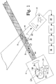
- the apparatus comprises a light pulse transmitter 1 and an optical receiver 3.
- the intersection of the transmit beam 2 of the transmitter 1 and the receive beam 4 of the receiver 3 forms a sample volume 9.
- the light pulse transmitter 1 typically comprises a light source 5 which may comprise, e.g., a laser diode, combined with optics 6.
- the optical output power of the transmitter 1 typically is approx. 20 W peak, and the light is emitted as short pulses with a duration of, e.g., 100 ns.
- the pulse rate is typically in the range 0.3-10 kHz.
- the light pulse transmitter 5 is combined with an optical receiver 19 which uses the same optics 6 as the transmitter section 5.
- the transmitter head further includes a data processing unit 11 with a main task to compute the distance of the reflecting front (e.g., fog or cloud) on the basis of the time delay between the transmitted pulse 16 and the return pulse 17.
- the forward scatter receiver 3 includes a receiver optics 7 and a detector section 8 for the measurement of light scattered by and/or reflected from particles 10 contained in the sample volume 9.
- the error component caused by stray light is separated from the detected signal, in block 14 the signal is digitized and stored in memory, in block 13 are performed the computational functions, and the visibility signal obtained from the computation is displayed with the help of block 12.
- the feedback arrangement of the optical signal in such a system based on a beam splitter 20 as shown in the diagram is implemented with the help of an optical fiber 23 optically connected to a feedback signal detector 21.
- the other end of the fiber 23 is placed on the opposite side of the beam splitter 20 relative to the receiver 19.
- the length of the fiber 23 is advantageously selected so that the delay caused by the fiber is equal to the return delay of the strongest error signal component. If the strongest error signal component is obtained from, e.g., the beam splitter 20, the delay caused by the fiber 23 must be adjusted equal to the optical signal propagation delay between the receiver 19 and the beam splitter 20.
- the delay implemented with the help of the fiber 23 must be set equal to the delay between the lens 6 and the beam splitter 20 multiplied by two.
- the photodetector elements can be placed physically as close to each other as possible, whereby these elements can be kept under maximally equal ambient conditions.
- the end of the fiber 23 can be adapted movable, whereby the error signal compensation is possible, besides by adjusting the detector bias voltage, through proper placement of the free end of the fiber 23. In practice, coarse adjustment of compensation occurs by mechanically rotating the fiber end, while the fine adjustment is effected electronically.
- the feedback signal in a system based on the use of a Y-coupler can be arranged with the help of an optical power splitter 24.
- the power split ratio can be selected as, e.g., 2:2.
- the signal delay via the optical feedback fiber 25 placed between the optical power splitter 24 and the feedback signal detector 21 is adapted essentially equal to the signal delay via the optical fiber 26 placed between the receiver 19 and the optical power splitter 24.
- the waveform of the optical input signal to a non-feedback-compensated receiver is shown in the upper graph.
- the optical leak at the start of the curve causes a transient pulse 34 with a peak intensity 35 of approx. 1,000 - 1,000,000 times the normal input signal level.
- this transient pulse 34 drives the amplifier of the receiver to saturation during the time interval 33.
- the amplifier recovers from this saturation, and due to the overload transient swing 32, any optical signal 36 received as backscatter from fog during this time remains undetected at the amplifier output.
- a measurement signal from, e.g., a cloud or fixed object can be obtained earliest at time instant 37. This signal may still be corrupted by the overload transient swing 32.
- the overload condition of the amplifier can be eliminated by connecting a conventional photodetector element 41 in a half-bridge configuration with the feedback signal detector element 42.
- both photodetector elements 41 and 42 are reverse-biased avalanche photodiodes.
- the bias voltage of the half-bridge can be fine-adjusted in such a manner that the transient error signal invoked by the optical leakage pulse can be cancelled with the help of the compensating feedback photodiode essentially completely.
- the bias voltage can be controlled in a continuous manner by first converting the analog signal into digital form with the help of an A/D converter 45 and then processing this digital signal in a data processing unit 47.
- the A/D converter 45 typically is a fast, so-called FLASH converter with, e.g., 50 ns sampling interval and 8-bit resolution.
- the output of the A/D converter 45 is taken to a FIFO (First-In/First-Out) sample buffer 48 prior to being taken to a microprocessor 47.
- the length of the buffer 48 may be, e.g., 512 samples.
- the microprocessor 47 controls the sampling operation via a control line 54 taken to both the sample buffer 48 and the A/D converter 45.
- the bias voltage control is implemented by taking a control signal from the data processing unit 47 to a bias voltage regulator 44 which controls the bias voltage applied over the photodiodes 41 and 42.
- the bias control can be implemented in a continuous manner as the data processing unit is capable of evaluating the accuracy of the compensation from the measurement signal, and thus can apply a differential increase or decrease to the bias voltage so as to attain complete compensation.
- the bias voltage control circuit is implemented with the help of a constant voltage regulator 40 connected to the positive voltage rail and a controllable voltage regulator 44 connected to the negative voltage rail, whereby the control signal is taken from the microprocessor 47 via a D/A converter 58 along a control line 56 to the latter regulator.
- the half-bridge 46 is advantageously provided with a temperature compensation circuit 49 connected to said voltage regulators 40 and 44.
- the half-bridge 46 formed by the photodiodes 41 and 42 can be considered to form a subtracting circuit in which the error signal component is subtracted from the measurement signal.
- the ceilometer section 1 of the apparatus illustrated in Fig. 1 or Fig. 2 detects and measures cloud base height, and during fog periods, its return signal profile also contains the fog distribution as a function of vertical height.
- the backscatter receiver 3 is situated at a height of approx. 1 m from the exit opening of the ceilometer 1 and measures light scatter at a forward angle of 20-45°, whereby visibility in the sample volume 9 described above can be computed from the receiver output signal by conventional means (blocks 12 - 15). If and when both measurement functions have been calibrated for exact visibility readings particularly under fog conditions, the visibility readings obtained by both measurement functions of the apparatus will be the same under fog conditions.
- the near-range signal of the ceilometer function will be relatively weaker (representing a relatively better visibility) than the forward scatter signal measured by the forward scatter receiver, as is evident from the discussion above. Thus, this situation is an indication of rain.
- the near-range signal of the ceilometer function will be relatively stronger (representing a relatively weaker visibility) than the forward scatter signal measured by the forward scatter receiver, as is evident from the discussion above. Thus, this situation is an indication of falling snow.
- a local ground fog can be detected by virtue of the apparatus from the situation that the vertical visibility profile in this case indicates a low fog height.
- the backward scatter receiver has such a high time resolution on its return signal that individual raindrops or snowflakes can be detected from the signal.
- this property provides redundancy in such a manner that, when the signal is detected to scatter from fog, it is possible to execute quality control by performing a cross-comparison of two different measurement functions, namely, the backward scatter versus the forward scatter, and/or to execute automatic calibration of one of the measurement functions.
- the apparatus can be provided with an air temperature sensor, whereby its reliability in the differentiation of rain from snowing is improved.
- the apparatus can be provided with a relative humidity sensor, whereby the detection of low-relative-humidity fog (haze in meteorological terminology), sandstorms and other special conditions of present weather characterized by low relative humidity become possible.
- a relative humidity sensor whereby the detection of low-relative-humidity fog (haze in meteorological terminology), sandstorms and other special conditions of present weather characterized by low relative humidity become possible.
- the apparatus can be complemented with a wind velocity meter, whereby the reliability of both blowing snow and local ground fog will be improved to a very high level.
- the apparatus can be equipped with a simple rain gauge, thus permitting the indication of liquid precipitation rate. This option provides more redundancy and reliability to the measurements.
- High transmitter output power is beneficial to the total performance of the apparatus as maximum information on the present weather is then obtained.
- use of a low-power pulsed light transmitter is also feasible within the spirit of the invention, requiring a compromise in the maximum range of the apparatus.
Landscapes
- Physics & Mathematics (AREA)
- Engineering & Computer Science (AREA)
- Computer Networks & Wireless Communication (AREA)
- Electromagnetism (AREA)
- General Physics & Mathematics (AREA)
- Radar, Positioning & Navigation (AREA)
- Remote Sensing (AREA)
- Investigating Or Analysing Materials By Optical Means (AREA)
- Optical Radar Systems And Details Thereof (AREA)
- Investigating Or Analyzing Materials By The Use Of Ultrasonic Waves (AREA)
- Road Signs Or Road Markings (AREA)
- Investigating Or Analyzing Materials By The Use Of Electric Means (AREA)
Applications Claiming Priority (3)
| Application Number | Priority Date | Filing Date | Title |
|---|---|---|---|
| FI940117A FI98766C (fi) | 1994-01-11 | 1994-01-11 | Laite ja menetelmä näkyvyyden ja vallitsevan sään mittaamiseksi |
| FI940117 | 1994-01-11 | ||
| FI94117 | 1994-01-11 |
Publications (3)
| Publication Number | Publication Date |
|---|---|
| EP0662619A2 true EP0662619A2 (fr) | 1995-07-12 |
| EP0662619A3 EP0662619A3 (fr) | 1996-05-15 |
| EP0662619B1 EP0662619B1 (fr) | 2000-10-11 |
Family
ID=8539380
Family Applications (1)
| Application Number | Title | Priority Date | Filing Date |
|---|---|---|---|
| EP94309783A Expired - Lifetime EP0662619B1 (fr) | 1994-01-11 | 1994-12-23 | Appareil et méthode pour mesurer la limite de visibilité et le temps actuel |
Country Status (7)
| Country | Link |
|---|---|
| US (1) | US5880836A (fr) |
| EP (1) | EP0662619B1 (fr) |
| JP (1) | JP3545823B2 (fr) |
| AT (1) | ATE196950T1 (fr) |
| AU (1) | AU697118B2 (fr) |
| DE (1) | DE69426110T2 (fr) |
| FI (1) | FI98766C (fr) |
Cited By (3)
| Publication number | Priority date | Publication date | Assignee | Title |
|---|---|---|---|---|
| RU2194290C1 (ru) * | 2001-04-02 | 2002-12-10 | Федеральное Государственное унитарное предприятие "Научно-исследовательский институт комплексных испытаний оптико-электронных приборов и систем" | Способ определения состояния замирания атмосферы |
| CN101281142B (zh) * | 2007-12-28 | 2011-06-29 | 深圳先进技术研究院 | 一种测量大气能见度的方法 |
| US10495787B2 (en) | 2016-06-16 | 2019-12-03 | I.M. Systems Group, Inc. | Integrated weather projection systems, methods, and apparatuses |
Families Citing this family (30)
| Publication number | Priority date | Publication date | Assignee | Title |
|---|---|---|---|---|
| US4609049A (en) * | 1982-04-26 | 1986-09-02 | Thomas Migdal | Rotary wheel type rock picker |
| JP3399827B2 (ja) * | 1998-03-23 | 2003-04-21 | 三菱電機株式会社 | 霧観測方法及び霧観測レーダシステム |
| DE19912971C1 (de) * | 1999-03-23 | 2000-09-21 | Daimler Chrysler Ag | Verfahren zur Erfassung der Lichtleistung einer Sendediode einer optischen Überwachungseinheit sowie geeignete Schaltungsanordnung |
| DE19931825A1 (de) * | 1999-07-08 | 2001-01-25 | Bosch Gmbh Robert | Vorrichtung zur Sichtweitenmessung |
| JP2001050894A (ja) * | 1999-08-16 | 2001-02-23 | Japan Atom Energy Res Inst | レーザー光により大気中の微量物質の濃度、距離等を遠隔かつオンラインで測定する方法 |
| US6546353B1 (en) | 1999-09-13 | 2003-04-08 | University Corporation For Atmospheric Research | Hot plate precipitation measuring system |
| US6650402B2 (en) * | 2000-02-10 | 2003-11-18 | Oceanit Laboratories, Inc. | Omni-directional cloud height indicator |
| US6476908B1 (en) | 2000-04-10 | 2002-11-05 | Eclipse Optics, Inc. | Optical probe |
| US20020075472A1 (en) * | 2000-09-22 | 2002-06-20 | Holton Carvel E. | Optical fiber ceilometer for meteorological cloud altitude sensing |
| JP2005528290A (ja) * | 2000-12-20 | 2005-09-22 | プロスペクツ コーポレイション | センサ装着システム |
| US6646725B1 (en) | 2001-07-11 | 2003-11-11 | Iowa Research Foundation | Multiple beam lidar system for wind measurement |
| US7602937B2 (en) * | 2004-06-08 | 2009-10-13 | International Electronic Machines Corporation | Image-based visibility measurement |
| CN100360957C (zh) * | 2005-03-10 | 2008-01-09 | 中国科学院合肥物质科学研究院 | 无人值守昼夜兼用便携式偏振-米散射激光雷达及其探测方法 |
| CA2628027C (fr) * | 2005-09-30 | 2013-04-23 | Institut National D'optique | Appareil de type lidar courte portee a reponse spatiale plate |
| US7274448B2 (en) * | 2005-09-30 | 2007-09-25 | Institut National D'optique | Short range LIDAR apparatus having a flat spatial response |
| US7388662B2 (en) * | 2005-09-30 | 2008-06-17 | Institut National D'optique | Real-time measuring of the spatial distribution of sprayed aerosol particles |
| JP5651882B2 (ja) * | 2008-12-05 | 2015-01-14 | 独立行政法人 宇宙航空研究開発機構 | 航空機搭載用風計測ライダー装置 |
| FI123974B (fi) | 2009-04-22 | 2014-01-15 | Vaisala Oyj | Menetelmä hydrometeoreja havaitsevan mittalaitteen yhteydessä sekä tähän liittyvä mittalaite |
| TWI546641B (zh) * | 2014-12-03 | 2016-08-21 | 瑞昱半導體股份有限公司 | 雪崩光電二極體的偏壓產生電路及相關的控制電路 |
| DE102015110826B4 (de) * | 2015-07-06 | 2023-03-30 | Dimeto Gmbh | Vorrichtung und Verfahren zur Messung von Niederschlag |
| CN105301674B (zh) * | 2015-11-20 | 2017-06-16 | 安徽省大气探测技术保障中心 | 气象光学视程检测装置 |
| US10520592B2 (en) | 2016-12-31 | 2019-12-31 | Waymo Llc | Light detection and ranging (LIDAR) device with an off-axis receiver |
| US10852438B2 (en) * | 2017-08-21 | 2020-12-01 | Caterpillar Inc. | LIDAR waveform classification |
| JP6714627B2 (ja) * | 2018-02-26 | 2020-06-24 | 株式会社興和 | 視界状況判別方法 |
| EP3633414B1 (fr) * | 2018-10-02 | 2022-03-02 | Vaisala, OYJ | Détecteur à lumiere diffusée vers l'avant |
| EP3633415B1 (fr) * | 2018-10-02 | 2021-04-14 | Vaisala, OYJ | Détecteur de diffusion avant |
| US20200132843A1 (en) * | 2018-10-26 | 2020-04-30 | GM Global Technology Operations LLC | Lidar system and control method thereof |
| US10921450B2 (en) * | 2019-04-24 | 2021-02-16 | Aeye, Inc. | Ladar system and method with frequency domain shuttering |
| CN115453572B (zh) * | 2022-08-25 | 2024-08-30 | 湖南国天电子科技有限公司 | 一种全光纤一体化光路的激光气象探测设备 |
| CN120405707B (zh) * | 2025-07-03 | 2025-10-21 | 南京信息工程大学 | 一种基于激光广域扫描低云雾的识别系统 |
Family Cites Families (16)
| Publication number | Priority date | Publication date | Assignee | Title |
|---|---|---|---|---|
| JPS5443374B2 (fr) * | 1972-03-29 | 1979-12-19 | ||
| US4289397A (en) * | 1979-07-20 | 1981-09-15 | Avco Everett Research Laboratory, Inc. | Laser ceilometer signal processing means |
| DE3002791C2 (de) * | 1980-01-26 | 1983-04-28 | Deutsche Forschungs- und Versuchsanstalt für Luft- und Raumfahrt e.V., 5000 Köln | Verfahren zur Messung der Sichtweite, Schrägsichtweite und Wolkenhöhe |
| SE451771B (sv) * | 1982-10-15 | 1987-10-26 | Asea Ab | Forfaringssett for metning av molnhojd |
| SE455541B (sv) * | 1983-04-18 | 1988-07-18 | Asea Ab | Forfarande for styrning av energien hos metsignaler fran en molnhojdsmetare samt molnhojdsmetare for genomforande av forfarandet |
| DE3536659A1 (de) * | 1984-12-27 | 1986-07-03 | Impulsphysik Gmbh, 2000 Hamburg | Vorrichtung zur wolkenhoehenmessung |
| US4613938A (en) * | 1985-01-25 | 1986-09-23 | Hss Inc. | Present weather observing system utilizing particulate size and velocity measurements |
| US4838692A (en) * | 1986-03-24 | 1989-06-13 | Champion International Corporation | Temperature-compensated apparatus and method for determining pulp stock consistency |
| US4937461A (en) * | 1988-08-22 | 1990-06-26 | Traina John E | Transmissometer having solid state light source |
| FI884142L (fi) * | 1988-09-08 | 1990-03-09 | Vaisala Oy | System foer maetning av ljusdispersion. |
| CA2000049C (fr) * | 1988-10-05 | 1995-08-22 | Christian Werner | Dispositif lidar servant a mesurer les turbidites atmospheriques |
| NL9001415A (nl) * | 1990-06-21 | 1992-01-16 | Ajax De Boer B V | Optische rook-, aerosol- en stofdetector en brandmeldingsapparaat met optische detector. |
| FI94559C (fi) * | 1992-07-30 | 1995-09-25 | Vaisala Oy | Menetelmä ja laitteisto ilmakehän näkyvyyden ja valosironnan mittaamiseksi, jossa laitteistossa lähetykselle ja vastaanotolle käytetään yhteistä optiikkaa |
| US5373367A (en) * | 1992-10-21 | 1994-12-13 | Qualimetrics, Inc. | Multiple angle and redundant visibility sensor |
| US5352901A (en) * | 1993-04-26 | 1994-10-04 | Cummins Electronics Company, Inc. | Forward and back scattering loss compensated smoke detector |
| US5444530A (en) * | 1993-06-07 | 1995-08-22 | Scientific Technology, Inc. | Weather identifier and visibility sensor |
-
1994
- 1994-01-11 FI FI940117A patent/FI98766C/fi active IP Right Grant
- 1994-12-23 EP EP94309783A patent/EP0662619B1/fr not_active Expired - Lifetime
- 1994-12-23 AT AT94309783T patent/ATE196950T1/de not_active IP Right Cessation
- 1994-12-23 DE DE69426110T patent/DE69426110T2/de not_active Expired - Fee Related
-
1995
- 1995-01-05 AU AU10152/95A patent/AU697118B2/en not_active Ceased
- 1995-01-10 JP JP00194595A patent/JP3545823B2/ja not_active Expired - Fee Related
-
1996
- 1996-10-24 US US08/736,282 patent/US5880836A/en not_active Expired - Fee Related
Cited By (5)
| Publication number | Priority date | Publication date | Assignee | Title |
|---|---|---|---|---|
| RU2194290C1 (ru) * | 2001-04-02 | 2002-12-10 | Федеральное Государственное унитарное предприятие "Научно-исследовательский институт комплексных испытаний оптико-электронных приборов и систем" | Способ определения состояния замирания атмосферы |
| CN101281142B (zh) * | 2007-12-28 | 2011-06-29 | 深圳先进技术研究院 | 一种测量大气能见度的方法 |
| US10495787B2 (en) | 2016-06-16 | 2019-12-03 | I.M. Systems Group, Inc. | Integrated weather projection systems, methods, and apparatuses |
| US11048022B2 (en) | 2016-06-16 | 2021-06-29 | I.M. Systems Group, Inc. | Integrated weather projection systems, methods, and apparatuses |
| US11841480B2 (en) | 2016-06-16 | 2023-12-12 | I.M. Systems Group, Inc. | Integrated weather projection systems, methods, and apparatuses |
Also Published As
| Publication number | Publication date |
|---|---|
| FI98766B (fi) | 1997-04-30 |
| FI940117A0 (fi) | 1994-01-11 |
| DE69426110T2 (de) | 2001-05-10 |
| AU697118B2 (en) | 1998-09-24 |
| US5880836A (en) | 1999-03-09 |
| ATE196950T1 (de) | 2000-10-15 |
| FI98766C (fi) | 1997-08-11 |
| FI940117L (fi) | 1995-07-12 |
| DE69426110D1 (de) | 2000-11-16 |
| AU1015295A (en) | 1995-07-20 |
| EP0662619A3 (fr) | 1996-05-15 |
| EP0662619B1 (fr) | 2000-10-11 |
| JP3545823B2 (ja) | 2004-07-21 |
| JPH07234280A (ja) | 1995-09-05 |
Similar Documents
| Publication | Publication Date | Title |
|---|---|---|
| EP0662619B1 (fr) | Appareil et méthode pour mesurer la limite de visibilité et le temps actuel | |
| US5118180A (en) | Method and apparatus for determining the range of vision of a motor vehicle driver upon encountering fog or other obstacle | |
| CA2219010C (fr) | Methode permettant de mesurer automatiquement une portee visuelle au moyen d'un systeme lidar | |
| US4605302A (en) | Cloud height measuring device with compensation for window fouling | |
| US4613938A (en) | Present weather observing system utilizing particulate size and velocity measurements | |
| US4717252A (en) | Method and apparatus for detecting distance and forming image of object in turbid medium using laser | |
| US7688249B2 (en) | Method for determining types of precipitation in the atmosphere | |
| GB2295670A (en) | Measuring flow vectors in gas flows | |
| FI94559C (fi) | Menetelmä ja laitteisto ilmakehän näkyvyyden ja valosironnan mittaamiseksi, jossa laitteistossa lähetykselle ja vastaanotolle käytetään yhteistä optiikkaa | |
| US10761004B2 (en) | Forward scatter sensor | |
| US11079312B2 (en) | Forward scatter sensor | |
| US4978221A (en) | Laser distance and altitude measuring apparatus | |
| RU2091711C1 (ru) | Способ измерения дальности и устройство для его осуществления | |
| SU1103083A1 (ru) | Устройство дл определени оптических характеристик атмосферы | |
| Maatta et al. | High-accuracy liquid level meter based on pulsed time of flight principle | |
| SU1658108A1 (ru) | Устройство дл определени оптических характеристик атмосферы | |
| RU2020520C1 (ru) | Способ определения скорости движения судна относительно водной поверхности и устройство для его осуществления | |
| SU646806A1 (ru) | Устройство дл измерени дальности видимости объектов | |
| SU918822A1 (ru) | Устройство дл определени оптических характеристик атмосферы | |
| GB2200810A (en) | Optical proximity detector | |
| Streicher | Verification of lidar visibility | |
| Herrmann et al. | Refractive index measurement with a THz triangulator and radar | |
| Werner et al. | Specification for a lidar apparatus for the detection of visibility | |
| Hooper | Shipboard Measurement of Cloud Bases and Average Surface Visibility with an Eye-Safe Lidar. | |
| Wang | Analysis of data from two laser weather identifier systems |
Legal Events
| Date | Code | Title | Description |
|---|---|---|---|
| PUAI | Public reference made under article 153(3) epc to a published international application that has entered the european phase |
Free format text: ORIGINAL CODE: 0009012 |
|
| AK | Designated contracting states |
Kind code of ref document: A2 Designated state(s): AT BE CH DE DK ES FR GB GR IE IT LI LU MC NL PT SE |
|
| RAX | Requested extension states of the european patent have changed |
Free format text: LT PAYMENT 950116;SI PAYMENT 950116 |
|
| PUAL | Search report despatched |
Free format text: ORIGINAL CODE: 0009013 |
|
| AK | Designated contracting states |
Kind code of ref document: A3 Designated state(s): AT BE CH DE DK ES FR GB GR IE IT LI LU MC NL PT SE |
|
| AX | Request for extension of the european patent |
Free format text: LT PAYMENT 950116;SI PAYMENT 950116 |
|
| 17P | Request for examination filed |
Effective date: 19960506 |
|
| 17Q | First examination report despatched |
Effective date: 19980212 |
|
| RAP1 | Party data changed (applicant data changed or rights of an application transferred) |
Owner name: VAISALA OYJ |
|
| GRAG | Despatch of communication of intention to grant |
Free format text: ORIGINAL CODE: EPIDOS AGRA |
|
| GRAG | Despatch of communication of intention to grant |
Free format text: ORIGINAL CODE: EPIDOS AGRA |
|
| GRAG | Despatch of communication of intention to grant |
Free format text: ORIGINAL CODE: EPIDOS AGRA |
|
| GRAH | Despatch of communication of intention to grant a patent |
Free format text: ORIGINAL CODE: EPIDOS IGRA |
|
| GRAH | Despatch of communication of intention to grant a patent |
Free format text: ORIGINAL CODE: EPIDOS IGRA |
|
| GRAA | (expected) grant |
Free format text: ORIGINAL CODE: 0009210 |
|
| AK | Designated contracting states |
Kind code of ref document: B1 Designated state(s): AT BE CH DE DK ES FR GB GR IE IT LI LU MC NL PT SE |
|
| AX | Request for extension of the european patent |
Free format text: LT PAYMENT 19950116;SI PAYMENT 19950116 |
|
| LTIE | Lt: invalidation of european patent or patent extension | ||
| PG25 | Lapsed in a contracting state [announced via postgrant information from national office to epo] |
Ref country code: NL Free format text: LAPSE BECAUSE OF FAILURE TO SUBMIT A TRANSLATION OF THE DESCRIPTION OR TO PAY THE FEE WITHIN THE PRESCRIBED TIME-LIMIT Effective date: 20001011 Ref country code: LI Free format text: LAPSE BECAUSE OF FAILURE TO SUBMIT A TRANSLATION OF THE DESCRIPTION OR TO PAY THE FEE WITHIN THE PRESCRIBED TIME-LIMIT Effective date: 20001011 Ref country code: IT Free format text: LAPSE BECAUSE OF FAILURE TO SUBMIT A TRANSLATION OF THE DESCRIPTION OR TO PAY THE FEE WITHIN THE PRE;WARNING: LAPSES OF ITALIAN PATENTS WITH EFFECTIVE DATE BEFORE 2007 MAY HAVE OCCURRED AT ANY TIME BEFORE 2007. THE CORRECT EFFECTIVE DATE MAY BE DIFFERENT FROM THE ONE RECORDED.SCRIBED TIME-LIMIT Effective date: 20001011 Ref country code: GR Free format text: LAPSE BECAUSE OF NON-PAYMENT OF DUE FEES Effective date: 20001011 Ref country code: ES Free format text: THE PATENT HAS BEEN ANNULLED BY A DECISION OF A NATIONAL AUTHORITY Effective date: 20001011 Ref country code: CH Free format text: LAPSE BECAUSE OF FAILURE TO SUBMIT A TRANSLATION OF THE DESCRIPTION OR TO PAY THE FEE WITHIN THE PRESCRIBED TIME-LIMIT Effective date: 20001011 Ref country code: BE Free format text: LAPSE BECAUSE OF FAILURE TO SUBMIT A TRANSLATION OF THE DESCRIPTION OR TO PAY THE FEE WITHIN THE PRESCRIBED TIME-LIMIT Effective date: 20001011 Ref country code: AT Free format text: LAPSE BECAUSE OF FAILURE TO SUBMIT A TRANSLATION OF THE DESCRIPTION OR TO PAY THE FEE WITHIN THE PRESCRIBED TIME-LIMIT Effective date: 20001011 |
|
| REF | Corresponds to: |
Ref document number: 196950 Country of ref document: AT Date of ref document: 20001015 Kind code of ref document: T |
|
| REG | Reference to a national code |
Ref country code: CH Ref legal event code: EP |
|
| REG | Reference to a national code |
Ref country code: IE Ref legal event code: FG4D |
|
| REF | Corresponds to: |
Ref document number: 69426110 Country of ref document: DE Date of ref document: 20001116 |
|
| PG25 | Lapsed in a contracting state [announced via postgrant information from national office to epo] |
Ref country code: LU Free format text: LAPSE BECAUSE OF NON-PAYMENT OF DUE FEES Effective date: 20001223 |
|
| PG25 | Lapsed in a contracting state [announced via postgrant information from national office to epo] |
Ref country code: IE Free format text: LAPSE BECAUSE OF NON-PAYMENT OF DUE FEES Effective date: 20001225 |
|
| PG25 | Lapsed in a contracting state [announced via postgrant information from national office to epo] |
Ref country code: MC Free format text: THE PATENT HAS BEEN ANNULLED BY A DECISION OF A NATIONAL AUTHORITY Effective date: 20001231 |
|
| ET | Fr: translation filed | ||
| PG25 | Lapsed in a contracting state [announced via postgrant information from national office to epo] |
Ref country code: SE Free format text: LAPSE BECAUSE OF FAILURE TO SUBMIT A TRANSLATION OF THE DESCRIPTION OR TO PAY THE FEE WITHIN THE PRESCRIBED TIME-LIMIT Effective date: 20010111 Ref country code: PT Free format text: LAPSE BECAUSE OF FAILURE TO SUBMIT A TRANSLATION OF THE DESCRIPTION OR TO PAY THE FEE WITHIN THE PRESCRIBED TIME-LIMIT Effective date: 20010111 Ref country code: DK Free format text: LAPSE BECAUSE OF FAILURE TO SUBMIT A TRANSLATION OF THE DESCRIPTION OR TO PAY THE FEE WITHIN THE PRESCRIBED TIME-LIMIT Effective date: 20010111 |
|
| NLV1 | Nl: lapsed or annulled due to failure to fulfill the requirements of art. 29p and 29m of the patents act | ||
| REG | Reference to a national code |
Ref country code: CH Ref legal event code: PL |
|
| PLBE | No opposition filed within time limit |
Free format text: ORIGINAL CODE: 0009261 |
|
| STAA | Information on the status of an ep patent application or granted ep patent |
Free format text: STATUS: NO OPPOSITION FILED WITHIN TIME LIMIT |
|
| 26N | No opposition filed | ||
| REG | Reference to a national code |
Ref country code: IE Ref legal event code: MM4A |
|
| REG | Reference to a national code |
Ref country code: GB Ref legal event code: IF02 |
|
| PGFP | Annual fee paid to national office [announced via postgrant information from national office to epo] |
Ref country code: FR Payment date: 20081212 Year of fee payment: 15 |
|
| PGFP | Annual fee paid to national office [announced via postgrant information from national office to epo] |
Ref country code: DE Payment date: 20081219 Year of fee payment: 15 |
|
| PGFP | Annual fee paid to national office [announced via postgrant information from national office to epo] |
Ref country code: GB Payment date: 20081216 Year of fee payment: 15 |
|
| GBPC | Gb: european patent ceased through non-payment of renewal fee |
Effective date: 20091223 |
|
| REG | Reference to a national code |
Ref country code: FR Ref legal event code: ST Effective date: 20100831 |
|
| PG25 | Lapsed in a contracting state [announced via postgrant information from national office to epo] |
Ref country code: FR Free format text: LAPSE BECAUSE OF NON-PAYMENT OF DUE FEES Effective date: 20091231 |
|
| PG25 | Lapsed in a contracting state [announced via postgrant information from national office to epo] |
Ref country code: DE Free format text: LAPSE BECAUSE OF NON-PAYMENT OF DUE FEES Effective date: 20100701 |
|
| PG25 | Lapsed in a contracting state [announced via postgrant information from national office to epo] |
Ref country code: GB Free format text: LAPSE BECAUSE OF NON-PAYMENT OF DUE FEES Effective date: 20091223 |