EP0663307A1 - An adjustable coil spring assembly - Google Patents
An adjustable coil spring assembly Download PDFInfo
- Publication number
- EP0663307A1 EP0663307A1 EP95300193A EP95300193A EP0663307A1 EP 0663307 A1 EP0663307 A1 EP 0663307A1 EP 95300193 A EP95300193 A EP 95300193A EP 95300193 A EP95300193 A EP 95300193A EP 0663307 A1 EP0663307 A1 EP 0663307A1
- Authority
- EP
- European Patent Office
- Prior art keywords
- spring
- spring assembly
- coil spring
- vehicle
- bracket
- Prior art date
- Legal status (The legal status is an assumption and is not a legal conclusion. Google has not performed a legal analysis and makes no representation as to the accuracy of the status listed.)
- Granted
Links
- 238000006243 chemical reaction Methods 0.000 claims abstract description 24
- 238000004873 anchoring Methods 0.000 claims abstract description 20
- 239000013589 supplement Substances 0.000 claims abstract description 7
- 230000015572 biosynthetic process Effects 0.000 claims description 4
- 239000000725 suspension Substances 0.000 claims description 2
- 238000005755 formation reaction Methods 0.000 claims 2
- 230000000712 assembly Effects 0.000 description 2
- 238000000429 assembly Methods 0.000 description 2
- 238000005452 bending Methods 0.000 description 2
- 238000009434 installation Methods 0.000 description 2
- 230000033001 locomotion Effects 0.000 description 2
- 230000004048 modification Effects 0.000 description 2
- 238000012986 modification Methods 0.000 description 2
- 230000029305 taxis Effects 0.000 description 2
- 238000007792 addition Methods 0.000 description 1
- 230000004075 alteration Effects 0.000 description 1
- 230000000694 effects Effects 0.000 description 1
- 238000004519 manufacturing process Methods 0.000 description 1
Images


Classifications
-
- B—PERFORMING OPERATIONS; TRANSPORTING
- B60—VEHICLES IN GENERAL
- B60G—VEHICLE SUSPENSION ARRANGEMENTS
- B60G11/00—Resilient suspensions characterised by arrangement, location or kind of springs
- B60G11/32—Resilient suspensions characterised by arrangement, location or kind of springs having springs of different kinds
- B60G11/34—Resilient suspensions characterised by arrangement, location or kind of springs having springs of different kinds including leaf springs
- B60G11/36—Resilient suspensions characterised by arrangement, location or kind of springs having springs of different kinds including leaf springs and also helical, spiral or coil springs
-
- F—MECHANICAL ENGINEERING; LIGHTING; HEATING; WEAPONS; BLASTING
- F16—ENGINEERING ELEMENTS AND UNITS; GENERAL MEASURES FOR PRODUCING AND MAINTAINING EFFECTIVE FUNCTIONING OF MACHINES OR INSTALLATIONS; THERMAL INSULATION IN GENERAL
- F16F—SPRINGS; SHOCK-ABSORBERS; MEANS FOR DAMPING VIBRATION
- F16F1/00—Springs
- F16F1/02—Springs made of steel or other material having low internal friction; Wound, torsion, leaf, cup, ring or the like springs, the material of the spring not being relevant
- F16F1/04—Wound springs
- F16F1/12—Attachments or mountings
- F16F1/125—Attachments or mountings where the end coils of the spring engage an axial insert
-
- F—MECHANICAL ENGINEERING; LIGHTING; HEATING; WEAPONS; BLASTING
- F16—ENGINEERING ELEMENTS AND UNITS; GENERAL MEASURES FOR PRODUCING AND MAINTAINING EFFECTIVE FUNCTIONING OF MACHINES OR INSTALLATIONS; THERMAL INSULATION IN GENERAL
- F16F—SPRINGS; SHOCK-ABSORBERS; MEANS FOR DAMPING VIBRATION
- F16F1/00—Springs
- F16F1/02—Springs made of steel or other material having low internal friction; Wound, torsion, leaf, cup, ring or the like springs, the material of the spring not being relevant
- F16F1/04—Wound springs
- F16F1/12—Attachments or mountings
- F16F1/127—Attachments or mountings allowing rotation about axis of spring
-
- B—PERFORMING OPERATIONS; TRANSPORTING
- B60—VEHICLES IN GENERAL
- B60G—VEHICLE SUSPENSION ARRANGEMENTS
- B60G2202/00—Indexing codes relating to the type of spring, damper or actuator
- B60G2202/10—Type of spring
- B60G2202/12—Wound spring
- B60G2202/122—Wound spring subjected to tension
Definitions
- THIS invention relates to an adjustable coil spring assembly.
- Mini-bus taxis which are often loaded to capacity, benefit markedly from such leaf spring supports in that the safety and comfort of passengers is enhanced. The wear and tear on the leaf springs of the vehicle is also minimized.
- a vehicle supplementary spring assembly adapted to supplement the spring force provided by a leaf spring of the vehicle, said supplementary spring assembly comprising: an elongate coil spring which forms an axially extending passage having a wall of helical configuration defined by the inner surface of the coils of the coil spring; a first anchoring insert having an outer surface with thread-like formation thereon dimensioned to be in threaded engagement with the wall of the passage and adapted to be screwed into one end of the coil spring; a first connector member connected to the anchoring insert and adapted to connect the supplementary spring assembly to a first reaction point on a vehicle; and a second connector member connected to the other end of the coil spring and adapted to connect the supplementary spring assembly to a second reaction point on a vehicle; said first and second reaction points being selected in use such that a tensile force applied between the reaction points will supplement the action of the leaf spring in supporting the vehicle, said supplementary spring assembly being adapted to apply a tensile force between said first and second reaction
- the first insert is preferably provided with an axial bore sized to accommodate a first connector member for connecting a first end of the spring to the first or second reaction member, the first connector member being axially movable and securable within the bore so as to allow further adjustment in overall length of the coil spring assembly.
- the adjustable coil spring assembly may include a second anchoring insert formed with a thread-like formation dimensioned to allow the second insert to be screwed into the other end of the passage by engaging the helically configured wall of the passage.
- the second insert may be provided with an axial bore sized to accommodate the second connector member, the second connector member being axially movable and securable within the bore so as to allow further adjustment in the overall length of the coil spring assembly.
- the first reaction member is constituted by an end of the leaf spring and the second reaction member is constituted by a point between opposed ends of the leaf spring.
- the first connector member may include a hook for engaging an eye at an end of the leaf spring, and the second connector member may be securable to an axle of the vehicle.
- the second connector member may include a bracket upon which are mounted two hooks for engaging the axle of the vehicle.
- At least one end of the coil spring assembly may be connected to its respective reaction member through an articulated connection.
- a connection bracket which is associated with the end of the coil spring which is adjacent the axle to be configured so as to align the coil spring such that its axis intersects with the axis of the axle.
- the connector member associated with the axle may comprise a bracket of elongate form adapted to be aligned generally transverse to the axis of the coil spring, said bracket having a central region which in use will be generally perpendicular to the axis of the coil spring and two outer regions which are co-planar with each other and angled relative to the central region.
- the coil spring is connected to the central region by a bolt which passes through a hole formed in a central region and screws into an anchoring insert located within the axially extending passage within the centre of the coil spring.
- the bolt may be connected to the bracket in an articulated manner such that the angular relationship between the bracket and the coil spring may vary as the axle moves up and down in use.
- the angle of inclination between the central region and the edge regions of the bracket may be selected such that, in the assembled condition, the coil spring assembly adopts a cranked configuration with the end of the coil spring adjacent to the axle being inclined downwardly towards the leaf spring as a consequence of the said angular relationship between the central region and the outer regions of the bracket.
- the bracket preferably comprises a forged plate with a concave recess formed around the hole passing through the central region, said bolt having a male cup bearing fitted thereto which locates within the concave recess and allows for said articulated connection between the bolt and the bracket. This arrangement permits the coil spring to remain straight as the leaf spring on the vehicle moves up and down.
- the invention also extends to arrangements wherein the axle of the vehicle is located below the leaf spring.
- a bracket which defines a reaction member associated with the axle is clamped between the upper side of the leaf spring and U-shaped bolts or other fastening means which are used to secure the axle to the leaf spring.
- the bracket may be a right-angled bracket having a foot portion adapted to be clamped between the upper side of the leaf spring and the U-shaped bolts, and an upstanding arm having a hole therein through which a bolt passes, the bolt being engageable with an anchoring insert screwed into the axially extending passage in the coil spring.
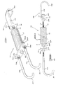
- Figures 1 and 2 show a vehicle supplementary spring assembly or adjustable coil spring assembly 10 for a leaf spring having a tension coil spring 12 which is round cylindrical in shape.
- a connector rod 14 is anchored to the spring 12 by a first anchoring insert 13 screwed into the spring 12.
- the rod 14 is threaded along its entire length and passes through a hole 15 which is defined in a flange 16 of a bracket or hook 18.
- the rod 14 is secured in the hole 15 by locking nuts 20 and 22 which are threaded onto the rod 14 on opposite sides of the flange 16.
- the bracket 18 includes a strip 24 extending at right angles from the flange 16 and terminating in a hook 26.
- a second insert 28 is screwed into the spring 12.
- a rectangular plate 30 is secured to the insert 28 by a connection bolt 32, which passes through a hole 33 formed in the centre of the plate 30 and is screwed into the insert 28.
- Two end holes (not visible), sized to accommodate the arms 34 and 36, are formed at opposing ends of the plate 30.
- the arms 34 and 36 are formed from cylindrical rods which are threaded at one end (34A,36A), and bent at the other end to form hooks 37. The threaded ends of the arms 34 and 36 are inserted through the end holes, and the arms 34 and 36 are secured in this position by locking nuts 38 and 38A which are located on the arms 34 and 36 on opposite sides of the plate 30.
- the inserts 13 and 28 have a helical groove forming a threaded outer surface 40 which allows the inserts 13 and 28 to be screwed into the complemental helical inner surface 40A of an axially extending passage 40B defined by the coils of the elongate spring 12.
- the inserts 13 and 28 are formed with threaded axial bores 39 and 41 sized to receive the respective threaded ends of the connector bolt 32 and the connector rod 14.
- the adjustable coil spring assembly 10 is mounted in place on the leaf spring 42 of a motor vehicle as is shown in Figure 5.
- the hook 26 engages an eye 44 of the leaf spring 42.
- the eye 44 carries a pin 45 which pivotably connects the leaf spring 42 to the chassis of the motor vehicle.
- the arms 34 and 36 are secured to the axle 46 of the vehicle by the hooks 37.
- the leaf spring 42 is secured to the axle 46 by a pair of U-bolts (only one of which is shown at 48) and a plate arrangement
- the U-bolts are mounted on either side of the leaf spring 42, and the hooks 37 engage the axle 46 on that portion of the axle 46 between the U-bolts.
- Installation of the adjustable coil spring assembly 10 involves jacking up the vehicle to which the assembly is to be installed, so that the leaf spring 42 is unloaded, and extending the assembly 10 in one or more of the following three ways.
- the overall length of the assembly 10 can be adjusted by loosening the nuts 20 and 22 that secure the connector rod 14 to the flange 16 of the bracket 18, whereafter the bracket 18 can be moved axially along the connector rod 14 towards or away from the spring 12.
- the nuts 38 and 38A may also be loosened and adjusted so as to reposition the plate relative to the arms 34 and 36.
- the insert 13 itself can be rotated within the passage defined by the spring 12, and thus axially moved within the passage.
- the insert 13 engages a number of the coils of the spring 12, and prevents these coils from elongating as the spring 12 is placed under tension.
- the coils of the spring 12 extending from behind the insert 13 towards the bracket 18 are naturally ineffective when the spring 12 is tensioned. Therefore, by screwing the insert 13 into the passage delined by the spring 12, and then rotating the insert 13 until it assumes a specified position within this passage, it is possible to adjust the overall length of the assembly 10, and also to adjust the tension in the spring by altering the number of coils of the spring 12 that will be placed under tension.
- the spring 12 may also be rotated relative to the insert 28.
- the hook 26 is connected to the eye 42, and the hooks 37 to the axle 46.
- the nuts 20 and 22 can then be rotated on the connector rod 14 until the spring 12 is placed under the required tension.
- the positions of the nuts 20 and 22 can then be adjusted from time to time to adjust the tension of the spring 12 if necessary.
- both the overall length and tension of the assembly 10 can be adjusted in three ways allows the assembly 10 to have a greater versatility than was previously possible.
- a standard assembly 10 is therefore able to be fitted to a far more diverse range of motor vehicles than previous dedicated assemblies, and this obviates the need to manufacture a range of coil spring assemblies to fit different motor vehicles.
- FIG. 6 another embodiment of the invention is shown. What is different in this embodiment is the configuration of a bracket 52 by means of which the coil spring 54 is connected to the axle 56.
- This arrangement is similar to that previously described wherein the assembly 50 has arms 58 with hooked ends 60 thereon which pass around the axle 56.
- the bracket 52 is not a flat planar member as previously described.
- the bracket 52 has a central region 62 and a pair of outer regions 64.
- the central region 62 has a hole 66 passing therethrough and a bolt 68 passes through that hole and into an anchoring insert 69 which is screwed into the coil spring 54.
- the hole 66 is of a larger diameter than the bolt 68 in order that the bolt is able to move angularly relative to the bracket 52. This will be described in more detail herebelow.
- the central region 62 of the bracket 52 is angularly offset from the outer regions 64.
- the angle of inclination is between 5° and 20° and the effect that in the assembled condition the adjustable coil spring assembly adopts a cranked configuration as shown clearly in Figure 7 of the drawings.
- the angle between the central region 62 and the outer regions 64 may alter for different vehicle suspension configurations.
- the angle between the central region 62 and outer region 64 is selected so that the end 70 of the coil spring is located nearer to the upper side of the leaf spring 72 than would be the case if the bracket 52 was made from flat plate.
- the arrangement is such that the axis 73 of the coil spring is perpendicular to and intersects with the axis 55 of the axle 56 and will remain substantially in this orientation as the axle moves up and down in use.
- the hole 66 in the central region 62 is preferably machined to the form of a concave recess or has a concave shaped bush 67 fitted thereto which will allow the bolt 68 to move in an articulated manner during movement up and down of the axle of the vehicle.
- the bolt 68 has a convex shaped cup washer 71 fitted thereto which will locate in the convex shaped hole in such a manner that the bolt 68 will be able to move in an articulated manner as previously described. This will ensure that at all times the coil spring is caused to extend and retract in a straight line and no lateral bending of the coil spring will take place due to a bending moment being placed on the coil spring.
- FIG. 9 an arrangement of adjustable coil spring assembly is shown suitable for use on vehicles, such as certain models of 4 X 4 vehicles, wherein the axle 82 is located below the coil spring assembly 84.
- a bracket 86 which is shown more clearly in Figure 10 of the drawings is clamped between the upper side 88 of the coil spring assembly 44 and the U-bolts 90 which in use hold the axle 82 to the leaf spring assembly 84.
- the bracket 86 comprises a foot portion 92 which is clamped by the U-bolts 90 and an upstanding arm 94 which is generally perpendicular to the foot portion 92.
- a hole 96 passes through the upstanding portion 94 and a bolt 98 passes through that hole 96 (in a similar manner to that previously described) in order to connect the coil spring 100.
- the bolt 98 is also able to move relative to the arm 94 in an articulated manner via a male cup washer 71A.
- brackets 52 and 86 may adopt different forms from that described herein, particularly if different connection arrangements are adopted for different vehicle or axle configurations.
Landscapes
- Engineering & Computer Science (AREA)
- General Engineering & Computer Science (AREA)
- Mechanical Engineering (AREA)
- Springs (AREA)
- Vehicle Body Suspensions (AREA)
Abstract
Description
- THIS invention relates to an adjustable coil spring assembly.
- There exists a need for supports for the leaf springs of vehicles that are subject to high loads, such as mini-bus taxis or trucks. Mini-bus taxis, which are often loaded to capacity, benefit markedly from such leaf spring supports in that the safety and comfort of passengers is enhanced. The wear and tear on the leaf springs of the vehicle is also minimized.
- Whilst it is known to provide support for leaf springs of vehicles, the installation of such supports usually requires some degree of structural modification to the vehicle. At least one support arrangement that does not require modification to the vehicle is described in South
African Patent 72/8488. However, this type of support arrangement is limited in versatility as an individual support arrangement can only be installed on a limited number of vehicle types due to the great diversity in vehicle dimensions. - According to the invention there is provided a vehicle supplementary spring assembly adapted to supplement the spring force provided by a leaf spring of the vehicle, said supplementary spring assembly comprising:
an elongate coil spring which forms an axially extending passage having a wall of helical configuration defined by the inner surface of the coils of the coil spring;
a first anchoring insert having an outer surface with thread-like formation thereon dimensioned to be in threaded engagement with the wall of the passage and adapted to be screwed into one end of the coil spring;
a first connector member connected to the anchoring insert and adapted to connect the supplementary spring assembly to a first reaction point on a vehicle; and
a second connector member connected to the other end of the coil spring and adapted to connect the supplementary spring assembly to a second reaction point on a vehicle;
said first and second reaction points being selected in use such that a tensile force applied between the reaction points will supplement the action of the leaf spring in supporting the vehicle, said supplementary spring assembly being adapted to apply a tensile force between said first and second reaction points, said tensile force being selectively variable by varying the position of the anchoring insert along the length of the passage. - The first insert is preferably provided with an axial bore sized to accommodate a first connector member for connecting a first end of the spring to the first or second reaction member, the first connector member being axially movable and securable within the bore so as to allow further adjustment in overall length of the coil spring assembly.
- The adjustable coil spring assembly may include a second anchoring insert formed with a thread-like formation dimensioned to allow the second insert to be screwed into the other end of the passage by engaging the helically configured wall of the passage.
- To further enhance the working of the assembly, the second insert may be provided with an axial bore sized to accommodate the second connector member, the second connector member being axially movable and securable within the bore so as to allow further adjustment in the overall length of the coil spring assembly.
- In a preferred embodiment of the invention, the first reaction member is constituted by an end of the leaf spring and the second reaction member is constituted by a point between opposed ends of the leaf spring.
- The first connector member may include a hook for engaging an eye at an end of the leaf spring, and the second connector member may be securable to an axle of the vehicle. The second connector member may include a bracket upon which are mounted two hooks for engaging the axle of the vehicle.
- At least one end of the coil spring assembly may be connected to its respective reaction member through an articulated connection. Another aspect of the invention provides for a connection bracket which is associated with the end of the coil spring which is adjacent the axle to be configured so as to align the coil spring such that its axis intersects with the axis of the axle.
- The connector member associated with the axle may comprise a bracket of elongate form adapted to be aligned generally transverse to the axis of the coil spring, said bracket having a central region which in use will be generally perpendicular to the axis of the coil spring and two outer regions which are co-planar with each other and angled relative to the central region.
- Preferably the coil spring is connected to the central region by a bolt which passes through a hole formed in a central region and screws into an anchoring insert located within the axially extending passage within the centre of the coil spring. The bolt may be connected to the bracket in an articulated manner such that the angular relationship between the bracket and the coil spring may vary as the axle moves up and down in use.
- The angle of inclination between the central region and the edge regions of the bracket may be selected such that, in the assembled condition, the coil spring assembly adopts a cranked configuration with the end of the coil spring adjacent to the axle being inclined downwardly towards the leaf spring as a consequence of the said angular relationship between the central region and the outer regions of the bracket. The bracket preferably comprises a forged plate with a concave recess formed around the hole passing through the central region, said bolt having a male cup bearing fitted thereto which locates within the concave recess and allows for said articulated connection between the bolt and the bracket. This arrangement permits the coil spring to remain straight as the leaf spring on the vehicle moves up and down.
- The invention also extends to arrangements wherein the axle of the vehicle is located below the leaf spring. In this arrangement a bracket which defines a reaction member associated with the axle is clamped between the upper side of the leaf spring and U-shaped bolts or other fastening means which are used to secure the axle to the leaf spring. The bracket may be a right-angled bracket having a foot portion adapted to be clamped between the upper side of the leaf spring and the U-shaped bolts, and an upstanding arm having a hole therein through which a bolt passes, the bolt being engageable with an anchoring insert screwed into the axially extending passage in the coil spring.
-
- Figure 1
- shows a pictorial view of an adjustable coil spring assembly according the invention;
- Figure 2
- shows an exploded view of the coil spring assembly of Figure 1;
- Figure 3
- shows an exploded view of the spring and inserts of Figure 2;
- Figure 4
- shows a cross sectional view on the line 4-4 of Figure 2, showing the inserts accommodated within the spring;
- Figure 5
- shows the adjustable coil spring assembly of Figures 1 and 2 installed on the leaf spring of a vehicle;
- Figure 6
- shows a perspective view of a coil spring assembly according to a second embodiment of the invention fitted to a motor vehicle;
- Figure 7
- shows a side view of the assembly shown in Figure 6;
- Figure 8
- shows an exploded view of the mounting bracket for the assembly shown in Figure 6;
- Figure 9
- shows a perspective view of a third embodiment of the invention; and
- Figure 10
- shows a perspective view of the mounting bracket for the assembly shown in Figure 9.
- Figures 1 and 2 show a vehicle supplementary spring assembly or adjustable coil spring assembly 10 for a leaf spring having a
tension coil spring 12 which is round cylindrical in shape. At one end of thespring 12, aconnector rod 14 is anchored to thespring 12 by afirst anchoring insert 13 screwed into thespring 12. Therod 14 is threaded along its entire length and passes through ahole 15 which is defined in aflange 16 of a bracket orhook 18. Therod 14 is secured in thehole 15 bylocking nuts rod 14 on opposite sides of theflange 16. Thebracket 18 includes astrip 24 extending at right angles from theflange 16 and terminating in ahook 26. - At the other end of the
spring 12, asecond insert 28 is screwed into thespring 12. Arectangular plate 30 is secured to theinsert 28 by aconnection bolt 32, which passes through ahole 33 formed in the centre of theplate 30 and is screwed into theinsert 28. Two end holes (not visible), sized to accommodate thearms plate 30. Thearms hooks 37. The threaded ends of thearms arms locking nuts arms plate 30. - Turning now to Figures 3 and 4, the
inserts outer surface 40 which allows theinserts inner surface 40A of an axially extending passage 40B defined by the coils of theelongate spring 12. Theinserts axial bores connector bolt 32 and theconnector rod 14. - The adjustable coil spring assembly 10 is mounted in place on the
leaf spring 42 of a motor vehicle as is shown in Figure 5. Thehook 26 engages aneye 44 of theleaf spring 42. Theeye 44 carries apin 45 which pivotably connects theleaf spring 42 to the chassis of the motor vehicle. At the other end of the coil spring assembly 10, thearms hooks 37. Theleaf spring 42 is secured to the axle 46 by a pair of U-bolts (only one of which is shown at 48) and a plate arrangement The U-bolts are mounted on either side of theleaf spring 42, and thehooks 37 engage the axle 46 on that portion of the axle 46 between the U-bolts. - Installation of the adjustable coil spring assembly 10 involves jacking up the vehicle to which the assembly is to be installed, so that the
leaf spring 42 is unloaded, and extending the assembly 10 in one or more of the following three ways. - Firstly, it will be understood that the overall length of the assembly 10 can be adjusted by loosening the nuts 20 and 22 that secure the
connector rod 14 to theflange 16 of thebracket 18, whereafter thebracket 18 can be moved axially along theconnector rod 14 towards or away from thespring 12. The nuts 38 and 38A may also be loosened and adjusted so as to reposition the plate relative to thearms - Secondly, it is possible to screw the
connector rod 14 through the threadedaxial bore 39 in theinsert 13 to vary the extent to which therod 14 protrudes from theinsert 13 within thespring 12. The effective length of therod 14, and the overall length of the assembly 10, is varied in this manner. - Thirdly, the
insert 13 itself can be rotated within the passage defined by thespring 12, and thus axially moved within the passage. When in place within thespring 12, theinsert 13 engages a number of the coils of thespring 12, and prevents these coils from elongating as thespring 12 is placed under tension. The coils of thespring 12 extending from behind theinsert 13 towards thebracket 18 are naturally ineffective when thespring 12 is tensioned. Therefore, by screwing theinsert 13 into the passage delined by thespring 12, and then rotating theinsert 13 until it assumes a specified position within this passage, it is possible to adjust the overall length of the assembly 10, and also to adjust the tension in the spring by altering the number of coils of thespring 12 that will be placed under tension. Thespring 12 may also be rotated relative to theinsert 28. - Once the assembly 10 has been extended by the required length which is determined by the spacing between the axle 46 and the
eye 44 of theleaf spring 42, thehook 26 is connected to theeye 42, and thehooks 37 to the axle 46. The nuts 20 and 22 can then be rotated on theconnector rod 14 until thespring 12 is placed under the required tension. The positions of the nuts 20 and 22 can then be adjusted from time to time to adjust the tension of thespring 12 if necessary. - The fact that both the overall length and tension of the assembly 10 can be adjusted in three ways allows the assembly 10 to have a greater versatility than was previously possible. A standard assembly 10 is therefore able to be fitted to a far more diverse range of motor vehicles than previous dedicated assemblies, and this obviates the need to manufacture a range of coil spring assemblies to fit different motor vehicles.
- Turning now to Figures 6 to 8 of the drawings, another embodiment of the invention is shown. What is different in this embodiment is the configuration of a
bracket 52 by means of which thecoil spring 54 is connected to theaxle 56. This arrangement is similar to that previously described wherein theassembly 50 has arms 58 with hooked ends 60 thereon which pass around theaxle 56. Thebracket 52, however, is not a flat planar member as previously described. Thebracket 52 has acentral region 62 and a pair ofouter regions 64. Thecentral region 62 has ahole 66 passing therethrough and a bolt 68 passes through that hole and into an anchoringinsert 69 which is screwed into thecoil spring 54. Thehole 66 is of a larger diameter than the bolt 68 in order that the bolt is able to move angularly relative to thebracket 52. This will be described in more detail herebelow. - The
central region 62 of thebracket 52 is angularly offset from theouter regions 64. The angle of inclination is between 5° and 20° and the effect that in the assembled condition the adjustable coil spring assembly adopts a cranked configuration as shown clearly in Figure 7 of the drawings. The angle between thecentral region 62 and theouter regions 64 may alter for different vehicle suspension configurations. The angle between thecentral region 62 andouter region 64 is selected so that the end 70 of the coil spring is located nearer to the upper side of theleaf spring 72 than would be the case if thebracket 52 was made from flat plate. The arrangement is such that theaxis 73 of the coil spring is perpendicular to and intersects with theaxis 55 of theaxle 56 and will remain substantially in this orientation as the axle moves up and down in use. - The
hole 66 in thecentral region 62 is preferably machined to the form of a concave recess or has a concave shapedbush 67 fitted thereto which will allow the bolt 68 to move in an articulated manner during movement up and down of the axle of the vehicle. To assist in this movement the bolt 68 has a convex shapedcup washer 71 fitted thereto which will locate in the convex shaped hole in such a manner that the bolt 68 will be able to move in an articulated manner as previously described. This will ensure that at all times the coil spring is caused to extend and retract in a straight line and no lateral bending of the coil spring will take place due to a bending moment being placed on the coil spring. - Turning now to Figures 9 and 10 of the drawings, an arrangement of adjustable coil spring assembly is shown suitable for use on vehicles, such as certain models of 4
X 4 vehicles, wherein theaxle 82 is located below thecoil spring assembly 84. In this arrangement a bracket 86 which is shown more clearly in Figure 10 of the drawings is clamped between the upper side 88 of thecoil spring assembly 44 and the U-bolts 90 which in use hold theaxle 82 to theleaf spring assembly 84. The bracket 86 comprises afoot portion 92 which is clamped by the U-bolts 90 and anupstanding arm 94 which is generally perpendicular to thefoot portion 92. A hole 96 passes through theupstanding portion 94 and abolt 98 passes through that hole 96 (in a similar manner to that previously described) in order to connect thecoil spring 100. Thebolt 98 is also able to move relative to thearm 94 in an articulated manner via amale cup washer 71A. - Various alterations and additions may be made to the embodiments described herein without departing from the scope of the invention. In particular, the
brackets 52 and 86 may adopt different forms from that described herein, particularly if different connection arrangements are adopted for different vehicle or axle configurations.
Claims (15)
- A vehicle supplementary spring assembly (10) adapted to supplement the spring force provided by a leaf spring (42) of the vehicle, characterized in that said supplementary spring assembly comprises:
an elongate coil spring (12) which forms an axially extending passage (40B) having a wall of helical configuration defined by the inner surface (40A) of the coils of the coil spring;
a first anchoring insert (13) having an outer surface with thread-like formations thereon dimensioned to be in threaded engagement with the helical wall of the passage (40B) and adapted to be screwed into one end of the coil spring (12);
a first connector member (18) connected to the first anchoring insert (13) and adapted to connect the supplementary spring assembly to a first reaction point (44) on a vehicle; and
a second connector member (34,36,37;52,58,60) connected to the other end of the coil spring and adapted to connect the supplementary spring assembly to a second reaction point (46) on the vehicle;
said first and second reaction points being selected in use such that a tensile force applied between the reaction points will supplement the action of the leaf spring in supporting the vehicle, said supplementary spring assembly being adapted to apply a tensile force between said first and second reaction points, said tensile force being selectively variable by varying the position of the anchoring insert (13) along the length of the passage (40B). - A spring assembly according to claim 1 characterized in that the first anchoring insert (13) is provided with a threaded axial bore (39), and the first connector member is provided with a threaded shank (14) adapted to screw into said axial bore, the first connector member being adapted to be screwed into or out of the axial bore (39) so as to provide means for further adjustment in the overall length and tensile force of the supplementary spring assembly.
- A spring assembly according to either one of the preceding claims characterized in that it includes a second anchoring insert (28) having thread-like formations on the outer surface thereof dimensioned to allow the second anchoring insert (28) to be screwed into the other end of the passage (40B) by engaging the helically configured wall (40A) of the passage.
- A spring assembly according to claim 3 characterized in that the second anchoring insert (28) has a threaded axial bore (41) and the second connector member (34,36,37) includes a threaded shank (34A,36A) adapted to screw into the threaded bore (41) of the second anchoring insert (28) to provide means for adjusting the overall length and tensile force of the supplementary spring assembly.
- A spring assembly according to any one of the preceding claims characterized in that one end of the spring assembly (10) is adapted to be connected to an end (44) of a said leaf spring (42) and a second reaction member (46) defining the second reaction point is located on said leaf spring at a point between the opposed ends thereof.
- A spring assembly according to any one of the preceding claims characterized in that the first connector member (18) includes a hook (26) for engaging an eye (44) at one end of the leaf spring (42), and the second connector member includes a hook (37) adapted to secure to an axle (46) which is supported by said leaf spring.
- A spring assembly according to any one of the preceding claims characterized in that at least one end of the coil spring assembly (10) is connected to its respective reaction point through an articulated connection (66,67,68,69).
- A spring assembly according to any one of the preceding claims characterized that said second connector is adapted to connect the spring assembly to an axle (56) of a vehicle and said second connector is configured to align the coil spring (12) so that its longitudinal axis (73) intersects with the axis (55) of the axle.
- A spring assembly according to claim 8 characterized in that the second connecter member includes a bracket (52) of elongate form adapted to be aligned generally transverse to the axis (73) of the coil spring, said bracket having a central region (62) which in use will be perpendicular to the axis of the coil spring, and two outer regions (64) which are co-planar with each other and angled relative to the central region.
- A spring assembly according to claim 9 characterized in that the coil spring (12) is connected to the central region (62) of the bracket by a bolt (68) which passes through a hole (66) formed in said central region, and screws into an anchoring insert (69) located within the passage of the coil spring.
- A spring assembly according to claim 10 characterized in that the bolt (68) is connected to the bracket (52) in an articulated manner such that the angular relationship between the bracket and the coil spring may vary as the axle moves up and down in use.
- A spring assembly according to claim 11 characterized in that the angle of inclination between the central region (62) and outer regions (64) of the bracket is selected such that, in the assembled condition, the spring assembly adopts a cranked configuration with the end (70) of the coil spring (12) adjacent to the axle being inclined towards the leaf spring (72) as a consequence of said angular relationship between the central region and outer regions of the bracket.
- A spring assembly according to claim 12 characterized in that the bracket (52) comprises a forged plate with a concave recess or bush (67) formed around said hole (66) passing through the central region, said bolt having a cup bearing (71) fitted thereto which locates within the concave recess or bush (67) and allows for said articulated connection between the bolt and the bracket.
- A spring assembly according to claim 5 characterised in that an axle (82) of the vehicle is located below the leaf spring (42) and in that the second reaction member is a bracket (86) mounted atop the leaf spring directly above the axle.
- A vehicle having a suspension system characterised in that it includes an axle (56) supported at opposite ends thereof on respective leaf springs (72) and a coil spring assembly (10) according to claim 1 associated with each of said leaf springs (72) which supplement the spring force provided by said leaf springs.
Applications Claiming Priority (2)
| Application Number | Priority Date | Filing Date | Title |
|---|---|---|---|
| ZA94198 | 1994-01-12 | ||
| ZA94198 | 1994-01-12 |
Publications (2)
| Publication Number | Publication Date |
|---|---|
| EP0663307A1 true EP0663307A1 (en) | 1995-07-19 |
| EP0663307B1 EP0663307B1 (en) | 1998-11-25 |
Family
ID=25583587
Family Applications (1)
| Application Number | Title | Priority Date | Filing Date |
|---|---|---|---|
| EP95300193A Expired - Lifetime EP0663307B1 (en) | 1994-01-12 | 1995-01-12 | An adjustable coil spring assembly |
Country Status (6)
| Country | Link |
|---|---|
| EP (1) | EP0663307B1 (en) |
| AP (1) | AP560A (en) |
| AT (1) | ATE173683T1 (en) |
| DE (1) | DE69506136T2 (en) |
| ES (1) | ES2128655T3 (en) |
| NZ (1) | NZ270324A (en) |
Cited By (6)
| Publication number | Priority date | Publication date | Assignee | Title |
|---|---|---|---|---|
| ES2149640A1 (en) * | 1996-03-21 | 2000-11-01 | Balay Sa | Improved device for subjection of washing machine tanks |
| WO2007138448A1 (en) * | 2006-05-29 | 2007-12-06 | William Wilfred Spencer | Connector assembly for a supplementary tension spring assembly |
| WO2010119402A1 (en) * | 2009-04-14 | 2010-10-21 | William Wilfred Spencer | A supplementary vehicle spring assembly |
| EP2243975A2 (en) | 2009-04-24 | 2010-10-27 | Müller, Andreas | Device for changing a leafspring characteristic |
| DE102013109613A1 (en) * | 2013-09-03 | 2015-03-05 | Brose Fahrzeugteile Gmbh & Co. Kommanditgesellschaft, Hallstadt | Coil spring connection |
| CN108425969A (en) * | 2018-05-07 | 2018-08-21 | 浙江武义张氏包装实业有限公司 | Stretcher in tension control structure |
Families Citing this family (2)
| Publication number | Priority date | Publication date | Assignee | Title |
|---|---|---|---|---|
| DE102022131048A1 (en) * | 2022-11-23 | 2024-05-23 | Explicatis Gmbh | Spring cradle suspension, spring cradle system and method for connecting a receiving device to at least one spring element |
| CN116006614A (en) * | 2023-01-03 | 2023-04-25 | 奇瑞汽车股份有限公司 | Damper and damping system |
Citations (6)
| Publication number | Priority date | Publication date | Assignee | Title |
|---|---|---|---|---|
| US2264070A (en) * | 1938-08-30 | 1941-11-25 | Lincoln K Davis | Vehicle spring control |
| US2560999A (en) * | 1950-02-24 | 1951-07-17 | Unzeitig Milvoy | Vehicle spring suspension |
| US2697600A (en) * | 1949-07-20 | 1954-12-21 | Jean A Gregoire | Suspension means for vehicles |
| FR1098875A (en) * | 1953-04-23 | 1955-08-23 | Toledo Woodhead Springs Ltd | Auxiliary device for semi-elliptical vehicle springs |
| ZA728488B (en) * | 1972-11-30 | 1974-06-26 | W Spencer | Improvements in springs |
| FR2318349A1 (en) * | 1975-07-18 | 1977-02-11 | Papousek Robert | Telescopic vehicle shock absorber - has spiral preloading spring surrounding damper body with adjustable mounting |
Family Cites Families (1)
| Publication number | Priority date | Publication date | Assignee | Title |
|---|---|---|---|---|
| AU7590874A (en) * | 1974-11-29 | 1976-06-03 | Spencer W W | Springs |
-
1995
- 1995-01-11 AP APAP/P/1995/000716A patent/AP560A/en active
- 1995-01-12 EP EP95300193A patent/EP0663307B1/en not_active Expired - Lifetime
- 1995-01-12 AT AT95300193T patent/ATE173683T1/en not_active IP Right Cessation
- 1995-01-12 NZ NZ270324A patent/NZ270324A/en unknown
- 1995-01-12 DE DE69506136T patent/DE69506136T2/en not_active Expired - Fee Related
- 1995-01-12 ES ES95300193T patent/ES2128655T3/en not_active Expired - Lifetime
Patent Citations (6)
| Publication number | Priority date | Publication date | Assignee | Title |
|---|---|---|---|---|
| US2264070A (en) * | 1938-08-30 | 1941-11-25 | Lincoln K Davis | Vehicle spring control |
| US2697600A (en) * | 1949-07-20 | 1954-12-21 | Jean A Gregoire | Suspension means for vehicles |
| US2560999A (en) * | 1950-02-24 | 1951-07-17 | Unzeitig Milvoy | Vehicle spring suspension |
| FR1098875A (en) * | 1953-04-23 | 1955-08-23 | Toledo Woodhead Springs Ltd | Auxiliary device for semi-elliptical vehicle springs |
| ZA728488B (en) * | 1972-11-30 | 1974-06-26 | W Spencer | Improvements in springs |
| FR2318349A1 (en) * | 1975-07-18 | 1977-02-11 | Papousek Robert | Telescopic vehicle shock absorber - has spiral preloading spring surrounding damper body with adjustable mounting |
Non-Patent Citations (1)
| Title |
|---|
| BERRY, W.R.: "Spring Design -IX", MECHANICAL WORLD & ENGINEERING RECORD, vol. 131, no. 3391, MANCHESTER (GB), pages 85 - 89 * |
Cited By (8)
| Publication number | Priority date | Publication date | Assignee | Title |
|---|---|---|---|---|
| ES2149640A1 (en) * | 1996-03-21 | 2000-11-01 | Balay Sa | Improved device for subjection of washing machine tanks |
| WO2007138448A1 (en) * | 2006-05-29 | 2007-12-06 | William Wilfred Spencer | Connector assembly for a supplementary tension spring assembly |
| WO2010119402A1 (en) * | 2009-04-14 | 2010-10-21 | William Wilfred Spencer | A supplementary vehicle spring assembly |
| EP2243975A2 (en) | 2009-04-24 | 2010-10-27 | Müller, Andreas | Device for changing a leafspring characteristic |
| DE102009003008A1 (en) | 2009-04-24 | 2010-11-25 | MÜLLER, Andreas | Device for changing a leaf spring characteristic |
| DE102013109613A1 (en) * | 2013-09-03 | 2015-03-05 | Brose Fahrzeugteile Gmbh & Co. Kommanditgesellschaft, Hallstadt | Coil spring connection |
| US10352387B2 (en) | 2013-09-03 | 2019-07-16 | Brose Fahrzeugteile Gmbh & Co. Kg, Hallstadt | Helical spring connection |
| CN108425969A (en) * | 2018-05-07 | 2018-08-21 | 浙江武义张氏包装实业有限公司 | Stretcher in tension control structure |
Also Published As
| Publication number | Publication date |
|---|---|
| AP560A (en) | 1996-11-15 |
| DE69506136D1 (en) | 1999-01-07 |
| ES2128655T3 (en) | 1999-05-16 |
| AP9500716A0 (en) | 1995-04-30 |
| EP0663307B1 (en) | 1998-11-25 |
| DE69506136T2 (en) | 1999-05-06 |
| ATE173683T1 (en) | 1998-12-15 |
| NZ270324A (en) | 1996-12-20 |
Similar Documents
| Publication | Publication Date | Title |
|---|---|---|
| US4033601A (en) | Adjustable hitch ball mount for a trailer hitch | |
| EP2398659B1 (en) | Support for pneumatic spring of wheel axle suspension. | |
| JP4943587B2 (en) | Suspension device | |
| US5647606A (en) | Suspension alignment device | |
| US6176501B1 (en) | Independent front suspension eccentric alignment device | |
| US5599038A (en) | Method and apparatus for lowering the suspension of a vehicle | |
| EP0663307A1 (en) | An adjustable coil spring assembly | |
| EP1051304B1 (en) | Suspension link assembly | |
| CA2129275C (en) | Adjustable coil spring assembly | |
| CA2280408C (en) | Support system for large antennas, including multi-beam antennas | |
| US4971352A (en) | Suspension alignment device | |
| US6247689B1 (en) | Apparatus for a vehicle suspension system | |
| EP0853011B1 (en) | Leaf spring stabiliser | |
| US7360778B2 (en) | Traction device | |
| US7597310B2 (en) | Leaf spring connection assembly | |
| WO2009027710A1 (en) | Leaf spring suspension system | |
| US6209897B1 (en) | Apparatus and method for mounting a suspension system | |
| US7699327B2 (en) | Wheel suspension | |
| US6158723A (en) | Stabilizer for leaf spring suspension device | |
| EP4132804B1 (en) | Forged flexible trailing arm having an omega shaped cross section | |
| JPS5847658A (en) | Mounting means for hydraulic steering cylinder | |
| JP7571650B2 (en) | Vehicle fastening structure | |
| JPH0642022Y2 (en) | Gutter hanging | |
| JPH05270240A (en) | Stabilizer mount | |
| JPH08338568A (en) | Long body support |
Legal Events
| Date | Code | Title | Description |
|---|---|---|---|
| PUAI | Public reference made under article 153(3) epc to a published international application that has entered the european phase |
Free format text: ORIGINAL CODE: 0009012 |
|
| AK | Designated contracting states |
Kind code of ref document: A1 Designated state(s): AT BE CH DE DK ES FR GR IE IT LI LU MC NL PT SE |
|
| RAX | Requested extension states of the european patent have changed |
Free format text: LT PAYMENT 950209;SI PAYMENT 950209 |
|
| 17P | Request for examination filed |
Effective date: 19960104 |
|
| 17Q | First examination report despatched |
Effective date: 19961017 |
|
| RBV | Designated contracting states (corrected) |
Designated state(s): AT BE CH DE DK ES FR GR IE IT LI LU MC NL PT SE |
|
| GRAG | Despatch of communication of intention to grant |
Free format text: ORIGINAL CODE: EPIDOS AGRA |
|
| GRAG | Despatch of communication of intention to grant |
Free format text: ORIGINAL CODE: EPIDOS AGRA |
|
| GRAH | Despatch of communication of intention to grant a patent |
Free format text: ORIGINAL CODE: EPIDOS IGRA |
|
| GRAH | Despatch of communication of intention to grant a patent |
Free format text: ORIGINAL CODE: EPIDOS IGRA |
|
| GRAA | (expected) grant |
Free format text: ORIGINAL CODE: 0009210 |
|
| AK | Designated contracting states |
Kind code of ref document: B1 Designated state(s): AT BE CH DE DK ES FR GR IE IT LI LU MC NL PT SE |
|
| AX | Request for extension of the european patent |
Free format text: LT PAYMENT 950209;SI PAYMENT 950209 |
|
| LTIE | Lt: invalidation of european patent or patent extension | ||
| PG25 | Lapsed in a contracting state [announced via postgrant information from national office to epo] |
Ref country code: SE Free format text: THE PATENT HAS BEEN ANNULLED BY A DECISION OF A NATIONAL AUTHORITY Effective date: 19981125 Ref country code: GR Free format text: LAPSE BECAUSE OF NON-PAYMENT OF DUE FEES Effective date: 19981125 Ref country code: BE Free format text: LAPSE BECAUSE OF FAILURE TO SUBMIT A TRANSLATION OF THE DESCRIPTION OR TO PAY THE FEE WITHIN THE PRESCRIBED TIME-LIMIT Effective date: 19981125 Ref country code: AT Free format text: LAPSE BECAUSE OF FAILURE TO SUBMIT A TRANSLATION OF THE DESCRIPTION OR TO PAY THE FEE WITHIN THE PRESCRIBED TIME-LIMIT Effective date: 19981125 |
|
| REF | Corresponds to: |
Ref document number: 173683 Country of ref document: AT Date of ref document: 19981215 Kind code of ref document: T |
|
| REG | Reference to a national code |
Ref country code: CH Ref legal event code: EP |
|
| REF | Corresponds to: |
Ref document number: 69506136 Country of ref document: DE Date of ref document: 19990107 |
|
| PG25 | Lapsed in a contracting state [announced via postgrant information from national office to epo] |
Ref country code: LU Free format text: LAPSE BECAUSE OF NON-PAYMENT OF DUE FEES Effective date: 19990112 |
|
| PG25 | Lapsed in a contracting state [announced via postgrant information from national office to epo] |
Ref country code: IE Free format text: LAPSE BECAUSE OF NON-PAYMENT OF DUE FEES Effective date: 19990125 |
|
| REG | Reference to a national code |
Ref country code: IE Ref legal event code: FG4D |
|
| ET | Fr: translation filed | ||
| ITF | It: translation for a ep patent filed | ||
| PG25 | Lapsed in a contracting state [announced via postgrant information from national office to epo] |
Ref country code: PT Free format text: LAPSE BECAUSE OF FAILURE TO SUBMIT A TRANSLATION OF THE DESCRIPTION OR TO PAY THE FEE WITHIN THE PRESCRIBED TIME-LIMIT Effective date: 19990225 Ref country code: DK Free format text: LAPSE BECAUSE OF FAILURE TO SUBMIT A TRANSLATION OF THE DESCRIPTION OR TO PAY THE FEE WITHIN THE PRESCRIBED TIME-LIMIT Effective date: 19990225 |
|
| REG | Reference to a national code |
Ref country code: CH Ref legal event code: NV Representative=s name: BOVARD AG PATENTANWAELTE |
|
| REG | Reference to a national code |
Ref country code: ES Ref legal event code: FG2A Ref document number: 2128655 Country of ref document: ES Kind code of ref document: T3 |
|
| PG25 | Lapsed in a contracting state [announced via postgrant information from national office to epo] |
Ref country code: MC Free format text: LAPSE BECAUSE OF NON-PAYMENT OF DUE FEES Effective date: 19990731 |
|
| PLBE | No opposition filed within time limit |
Free format text: ORIGINAL CODE: 0009261 |
|
| STAA | Information on the status of an ep patent application or granted ep patent |
Free format text: STATUS: NO OPPOSITION FILED WITHIN TIME LIMIT |
|
| 26N | No opposition filed | ||
| REG | Reference to a national code |
Ref country code: IE Ref legal event code: MM4A |
|
| PG25 | Lapsed in a contracting state [announced via postgrant information from national office to epo] |
Ref country code: IT Free format text: LAPSE BECAUSE OF NON-PAYMENT OF DUE FEES Effective date: 20050112 |
|
| PGFP | Annual fee paid to national office [announced via postgrant information from national office to epo] |
Ref country code: CH Payment date: 20050117 Year of fee payment: 11 |
|
| PGFP | Annual fee paid to national office [announced via postgrant information from national office to epo] |
Ref country code: DE Payment date: 20050120 Year of fee payment: 11 |
|
| PGFP | Annual fee paid to national office [announced via postgrant information from national office to epo] |
Ref country code: NL Payment date: 20050123 Year of fee payment: 11 |
|
| PGFP | Annual fee paid to national office [announced via postgrant information from national office to epo] |
Ref country code: FR Payment date: 20050125 Year of fee payment: 11 |
|
| PGFP | Annual fee paid to national office [announced via postgrant information from national office to epo] |
Ref country code: ES Payment date: 20050202 Year of fee payment: 11 |
|
| PG25 | Lapsed in a contracting state [announced via postgrant information from national office to epo] |
Ref country code: ES Free format text: LAPSE BECAUSE OF NON-PAYMENT OF DUE FEES Effective date: 20060113 |
|
| PG25 | Lapsed in a contracting state [announced via postgrant information from national office to epo] |
Ref country code: LI Free format text: LAPSE BECAUSE OF NON-PAYMENT OF DUE FEES Effective date: 20060131 Ref country code: FR Free format text: LAPSE BECAUSE OF NON-PAYMENT OF DUE FEES Effective date: 20060131 Ref country code: CH Free format text: LAPSE BECAUSE OF NON-PAYMENT OF DUE FEES Effective date: 20060131 |
|
| PG25 | Lapsed in a contracting state [announced via postgrant information from national office to epo] |
Ref country code: NL Free format text: LAPSE BECAUSE OF NON-PAYMENT OF DUE FEES Effective date: 20060801 Ref country code: DE Free format text: LAPSE BECAUSE OF NON-PAYMENT OF DUE FEES Effective date: 20060801 |
|
| REG | Reference to a national code |
Ref country code: CH Ref legal event code: PL |
|
| NLV4 | Nl: lapsed or anulled due to non-payment of the annual fee |
Effective date: 20060801 |
|
| REG | Reference to a national code |
Ref country code: FR Ref legal event code: ST Effective date: 20060929 |
|
| REG | Reference to a national code |
Ref country code: ES Ref legal event code: FD2A Effective date: 20060113 |
|
| PGFP | Annual fee paid to national office [announced via postgrant information from national office to epo] |
Ref country code: IT Payment date: 20060131 Year of fee payment: 12 |
|
| PGRI | Patent reinstated in contracting state [announced from national office to epo] |
Ref country code: IT Effective date: 20080301 |
|
| PGRI | Patent reinstated in contracting state [announced from national office to epo] |
Ref country code: IT Effective date: 20080301 |