EP0664499A1 - Système de commande pour assemblage cardan - Google Patents
Système de commande pour assemblage cardan Download PDFInfo
- Publication number
- EP0664499A1 EP0664499A1 EP95100903A EP95100903A EP0664499A1 EP 0664499 A1 EP0664499 A1 EP 0664499A1 EP 95100903 A EP95100903 A EP 95100903A EP 95100903 A EP95100903 A EP 95100903A EP 0664499 A1 EP0664499 A1 EP 0664499A1
- Authority
- EP
- European Patent Office
- Prior art keywords
- gimbal
- antenna
- control
- coupled
- signals
- Prior art date
- Legal status (The legal status is an assumption and is not a legal conclusion. Google has not performed a legal analysis and makes no representation as to the accuracy of the status listed.)
- Granted
Links
- 238000012545 processing Methods 0.000 claims abstract description 18
- 238000005259 measurement Methods 0.000 claims description 29
- 238000012937 correction Methods 0.000 claims description 7
- 238000000034 method Methods 0.000 claims description 3
- 230000010354 integration Effects 0.000 claims 3
- 230000033001 locomotion Effects 0.000 description 13
- 230000003287 optical effect Effects 0.000 description 12
- 238000004891 communication Methods 0.000 description 10
- 238000010586 diagram Methods 0.000 description 9
- 238000013461 design Methods 0.000 description 7
- 230000008901 benefit Effects 0.000 description 6
- 238000001914 filtration Methods 0.000 description 4
- 230000003993 interaction Effects 0.000 description 3
- 230000006641 stabilisation Effects 0.000 description 3
- 238000011105 stabilization Methods 0.000 description 3
- 238000006243 chemical reaction Methods 0.000 description 2
- 238000013016 damping Methods 0.000 description 2
- 238000012546 transfer Methods 0.000 description 2
- 230000003190 augmentative effect Effects 0.000 description 1
- 230000001427 coherent effect Effects 0.000 description 1
- 238000001514 detection method Methods 0.000 description 1
- 238000005516 engineering process Methods 0.000 description 1
- 238000005457 optimization Methods 0.000 description 1
Images


Classifications
-
- H—ELECTRICITY
- H01—ELECTRIC ELEMENTS
- H01Q—ANTENNAS, i.e. RADIO AERIALS
- H01Q1/00—Details of, or arrangements associated with, antennas
- H01Q1/12—Supports; Mounting means
- H01Q1/18—Means for stabilising antennas on an unstable platform
-
- B—PERFORMING OPERATIONS; TRANSPORTING
- B64—AIRCRAFT; AVIATION; COSMONAUTICS
- B64G—COSMONAUTICS; VEHICLES OR EQUIPMENT THEREFOR
- B64G1/00—Cosmonautic vehicles
- B64G1/22—Parts of, or equipment specially adapted for fitting in or to, cosmonautic vehicles
-
- B—PERFORMING OPERATIONS; TRANSPORTING
- B64—AIRCRAFT; AVIATION; COSMONAUTICS
- B64G—COSMONAUTICS; VEHICLES OR EQUIPMENT THEREFOR
- B64G1/00—Cosmonautic vehicles
- B64G1/22—Parts of, or equipment specially adapted for fitting in or to, cosmonautic vehicles
- B64G1/24—Guiding or controlling apparatus, e.g. for attitude control
- B64G1/36—Guiding or controlling apparatus, e.g. for attitude control using sensors, e.g. sun-sensors, horizon sensors
- B64G1/369—Guiding or controlling apparatus, e.g. for attitude control using sensors, e.g. sun-sensors, horizon sensors using gyroscopes as attitude sensors
Definitions
- the present invention relates generally to gimbal control systems, and more particularly, to a gimbal control system that employs inner and outer control loops.
- a variety of gimbal control systems have been developed for use in controlling the pointing direction of satellite antennas.
- a gimbal control system employed on the MILSTAR spacecraft has resolvers and autotrack receivers. However, they use one or the other, never both at the same time.
- the current-generation TDRSS satellite uses an autotrack receiver as a pointing reference for its gimbal. However, it does not have a resolver.
- When performing "program track" (or open-loop) pointing it keeps track of the antenna's position by counting motor steps. Gross updates of the antenna's position are available from potentiometers, but are not used in any closed-loop algorithms.
- Satellites such as INTELSAT VI or AUSSAT-B use ground-based beacons as pointing references for their antennas. These beacon tracking systems are much like the TDRSS design, in that they do not have a resolver but keep track of antenna position by counting steps.
- U.S. Patent 5,062,592 granted to H. Kishimoto, issued 11/5/91, entitled "Orientation Control Apparatus for Space Vehicle", describes a spacecraft with a gimballed antenna.
- the antenna has an RF autotrack sensor to sense its inertial position.
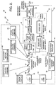
- the inner control loop 21 is comprised of the resolver 14 and a resolver processing circuit 22.
- the resolver 14 is adapted to provide an output signal 51 indicative of gimbal angles relative to the spacecraft 12.
- the resolver processing circuit 22 is adapted to process the resolver measurement and provide an output signal 18a indicative of the relative angular position of the antenna 11 (the measured gimbal angle).
- the inner control loop 21 also comprises a compensation circuit 25, a step generator 26, or motor driver 26, that is adapted to generate step commands, and a gimbal drive 27 that produces a desired gimbal angle signal that drives the gimbal 13.
- command signals that are determinative of control modes provided by the gimbal control system 10 are shown coupled to selected terminal of the switches 36, 37, 38 and include a program track profile 41, a compensated ground command 42, a spacecraft motion compensation signal 43, uncompensated ground command 44, and a store position command 45.
- step generator 26 or motor driver 26 to provide a step rate command for a stepping gimbal 13 or a torque command for a direct-drive gimbal 13.
- step command is then sent to gimbal drive 27.
- the resolver feedback signal provided by the resolver 14 provides a measurement of the relative angle between the spacecraft 12 and the gimballed antenna 11. This allows for stabilization of gimbal compliance by phase-lead compensation.
- derivative feedback may increase the damping of a flexible mode to any desired value. This allows for at least one or two flexible modes to be within the bandwidth of the gimbal control system 10 and therefore a higher-bandwidth gimbal control system 10 may be designed.
- an accurate high-bandwidth measurement of the gimbal angle enables improved performance, and more accurate control of the antenna 11. Since a stiffer gimbal drive tends to be heavier, the use of the resolver 14 enables antenna 11 control accuracy to be maintained with a lighter weight gimbal 13.
- Fig. 3 is a block diagram illustrating an inner control loop 21a (compensation loop 21) for a stepper drive gimbal 13 that may be employed in the gimbal control system 10 of Fig.2.
- Fig. 4 is a block diagram illustrating the inner control loop 21b for a direct drive gimbal 13 that may be employed in the gimbal control system 10 of Fig. 2.
- the inner control loop 21b comprises a PID (proportionaI-integrator-derivative) type integrator 25b as is shown in Fig. 4.
- This inner control loop 21b allows the control system 10 to achieve zero steady-state error in the presence of constant or slowly-varying friction in the gimbal 13.
- the inner control loop 21b may also include a notch filter 28 or additional phase lead to stabilize flexible modes in the gimbal 13 or antenna 11, and may be implemented with either analog or digital electronics, or a microprocessor.
- the antenna 11 is in a "store” mode and is steered to a predetermined desired orientation with respect to the spacecraft 12 and then left there. This position may be such as to minimize solar torques on the spacecraft 12. If the first switch 36 is in position 2, the gimbal 13 is in an "uncompensated ground command mode,” and is steered to a ground-commanded desired position with respect to the spacecraft 12.
- the gimbal 13 is in a "compensated ground command mode." In this mode, the gimbal 13 is served to a desired ground-commanded inertial orientation, and spacecraft 12 motion is compensated for by adding in a signal representing the orientation of the spacecraft 12 ("spacecraft motion compensation").
- the orientation of the spacecraft 12 is typically derived by sensors disposed on the spacecraft 12 (for example, star sensors or gyros). The accuracy of the control provided by this mode is limited by the accuracy of the sensors and the accuracy of knowledge of target position.
- the gimbal 13 is in a "corrected program track mode.”
- This mode is similar to the compensated ground command mode, except that instead of a real-time ground commanded position, a stored commanded position profile is used.
- This profile may, for example, be stored in the form of a table lookup or as a polynomial function that is evaluated on the spacecraft 12. This is a "program track" mode of operation.
- the inner and outer loop autotrack reference provided by the gimbal control system 10 will now be described. Assume that the gimbal control system 10 is in the corrected program track mode (i.e., the first switch 36 is in position 3, the second switch 37 is in position 2, and the third switch 38 is in position 1). If the target toward which the antenna 11 is steered is an autotracking target (i.e., if it has a communications signal that is used as an autotrack reference), then the autotrack signal strength is monitored by the autotrack receiver 19. When the autotrack signal strength has exceeded a predetermined threshold, the autotrack reference is declared present and the third switch 38 is closed (position 2). At that instant, an autotrack error signal is available for controlling the gimbal 13. As is shown in Fig. 2, the autotrack signal is a direct measurement of the boresight angle of the antenna 11 with respect to the target. The description below illustrates how the autotrack signal is used in combination with the resolver signal to control the gimbal 13.
- the gimbal control system 10 of the present invention following low-pass filtering of the autotrack signal in the filter 33 and conversion to a digital signal in the A/D converter 34, it is passed through a P-I (proportional-integral) filter 35.
- the P-I filter 35 has a continuous-time transfer function given by
- the combination of the anti-aliasing low-pass filter 33 and the P-I filter 35 ideally result in a low-bandwidth reference signal, in that this signal has its cutoff frequency below that of the inner-loop 21 incorporating resolver feedback used in the gimbal control system 10.
- the autotrack signal results in an accurate, but slowly-varying, correction to the stored program track profile 41 equal to the deviation of the actual target position from the stored program track profile.
- the output of the P-I filter 35 is exactly this difference.
- the input to the P-I filter 35 is zero because the closed-loop action of the two-loop gimbal control system 10 causes the antenna 11 to track exactly on the target, and the sensed autotrack error to be zero.
- the output of the P-I filter 35 is equal and opposite to the program track error.
- the sum of the program track profile 41 and the output of the P-I filter 35 define the exact target position.
- This summed signal is the input to the inner control loop 21.
- This input signal matches the target's position with small deviations due to disturbances and noise.
- the inner control loop 21 servoes the gimbal 13 to track this commanded profile, and the compensation provided by the P-I filter 35 corrects the commanded profile to null the small deviations from the exact target position, resulting in exactly the gimbal motions necessary to track the target.
- the benefit of using the inner control loop 21 in combination with the outer control loop 23 even after acquiring the autotrack reference signal is that the resolver is an inherently less noisy sensor than the autotrack signal and allows for a higher-bandwidth, higher-performance control system 10 than that which could be obtained using the autotrack signal 18c alone.
- Gimbal control may be performed with the commanded program track profile 41 as a reference to the resolver-based inner control loop 21.
- the inner control loop 21, along with the use of spacecraft motion compensation, tracks out most disturbances resulting from the body of the spacecraft 12 ("spacecraft bus motion").
- the autotrack signal provides a low-bandwidth correction signal for the relatively fast inner control loop 21 to correct for unknown biases and unknown motions of the target.
- An added benefit of using the output of the resolver 14 as the main feedback signal is that the control system 10 is less sensitive to flexibility of the gimbal 13 or antenna 11, since the resolver 14 is co-located with the gimbal 13.
- An alternative is to use the autotrack receiver 19 as the primary feedback sensor, augmented with feedforward of the spacecraft bus motion. This combination offers no direct measurement of gimbal deflections due to flexibility, and the control bandwidth is more limited by the need to stabilize gimbal flexible interactions.
- using the resolver 14 in the inner control loop 21 allows for active control of the gimbal flexible dynamics and therefore a higher-bandwidth control system 10 with the same gimbal stiffness, or an equal bandwidth control system 10 with a lighter-weight, less stiff gimbal 13.
- the above discussion refers to flexibility between the resolver and the autotrack sensor. Resolver feedback does not mitigate flexibility between the gimbal drive and resolver feedback (this would typically be flexibility in the gear train).
- the present gimbal control system 10 still operates. Assuming that the most recent value of the program track profile 41 is stored, after the program track ceases to be updated, the output of the P-I filter 35 steadily grows to equal the difference between the current target position and the most recent value of the program track profile. Depending on how the parameters of the gimbal control system 10 are selected, it may be made to behave arbitrarily close to the behavior of a control loop with autotrack feedback alone.
- a multi-loop control system 10 for a gimballed antenna 11 that employs devices 14 for measuring both absolute line-of-sight (an autotrack receiver 32 or beacon tracker) and relative angular position (a resolver 14).
- the control system 9 uses both signals simultaneously, thereby increasing the performance and pointing accuracy capability.
- Two control loops 21, 23 operate simultaneously to provide for optimum performance.
- the first loop 21 is an inner high-bandwidth control loop that uses the relative gimbal angle measurement to control pointing of the antenna 11 along a precommanded profile.
- the inner loop 21 may run alone to provide for coarse pointing.
- the line-of sight measurement is used in a low-bandwidth outer loop 23 to provide corrections to the command profile of the inner loop 23.
- Control logic 36, 37, 38 is provided that allowes switching between several control modes.
Landscapes
- Engineering & Computer Science (AREA)
- Remote Sensing (AREA)
- Aviation & Aerospace Engineering (AREA)
- Chemical & Material Sciences (AREA)
- Combustion & Propulsion (AREA)
- Radar, Positioning & Navigation (AREA)
- Variable-Direction Aerials And Aerial Arrays (AREA)
- Details Of Aerials (AREA)
Applications Claiming Priority (2)
| Application Number | Priority Date | Filing Date | Title |
|---|---|---|---|
| US08/185,346 US5557285A (en) | 1994-01-24 | 1994-01-24 | Gimbal control system |
| US185346 | 1994-01-24 |
Publications (2)
| Publication Number | Publication Date |
|---|---|
| EP0664499A1 true EP0664499A1 (fr) | 1995-07-26 |
| EP0664499B1 EP0664499B1 (fr) | 1999-06-23 |
Family
ID=22680614
Family Applications (1)
| Application Number | Title | Priority Date | Filing Date |
|---|---|---|---|
| EP95100903A Expired - Lifetime EP0664499B1 (fr) | 1994-01-24 | 1995-01-24 | Système de commande pour assemblage cardan |
Country Status (4)
| Country | Link |
|---|---|
| US (1) | US5557285A (fr) |
| EP (1) | EP0664499B1 (fr) |
| JP (1) | JP3488301B2 (fr) |
| DE (1) | DE69510383T2 (fr) |
Cited By (6)
| Publication number | Priority date | Publication date | Assignee | Title |
|---|---|---|---|---|
| FR2838872A1 (fr) * | 2002-04-22 | 2003-10-24 | Mitsubishi Electric Corp | Appareil de mesure de deplacement et d'inclinaison et systeme d'antenne |
| DE19937765B4 (de) * | 1999-08-10 | 2005-04-07 | Eads Astrium Gmbh | Einrichtung zum genauen Positionieren einer Antenne |
| DE102008024813A1 (de) * | 2008-05-23 | 2009-11-26 | Deutsches Zentrum für Luft- und Raumfahrt e.V. | Vorrichtung und Verfahren zur kabellosen, punktförmigen Datenübertragung |
| WO2011162614A1 (fr) * | 2010-05-28 | 2011-12-29 | Kongsberg Seatex As | Procédé et système pour le positionnement d'une antenne, d'un télescope, d'un dispositif de pointage ou tout autre dispositif similaire monté sur une plate-forme mobile |
| CN103915673A (zh) * | 2014-03-24 | 2014-07-09 | 中国人民解放军63680部队 | 船载a-e-c三轴卫星通信天线波束指向跟踪控制方法 |
| US11019265B1 (en) | 2020-11-04 | 2021-05-25 | Bae Systems Information And Electronic Systems Integration Inc. | Optimized motion compensation via fast steering mirror and roll axis gimbal |
Families Citing this family (25)
| Publication number | Priority date | Publication date | Assignee | Title |
|---|---|---|---|---|
| JP2807639B2 (ja) * | 1995-03-31 | 1998-10-08 | 株式会社豊田中央研究所 | 追尾アンテナ装置 |
| US5873048A (en) * | 1995-07-27 | 1999-02-16 | Lucent Technologies Inc. | Locator and method for a wireless communication system |
| JP3031216B2 (ja) | 1995-10-25 | 2000-04-10 | 日本電気株式会社 | 宇宙機搭載用光アンテナの指向角制御装置 |
| JP3627377B2 (ja) * | 1996-05-29 | 2005-03-09 | トヨタ自動車株式会社 | 車載用衛星信号受信装置 |
| US6002364A (en) * | 1997-07-31 | 1999-12-14 | Cbs Corporation | Apparatus and method for beam steering control system of a mobile satellite communications antenna |
| US6396446B1 (en) | 1999-02-16 | 2002-05-28 | Gentex Corporation | Microwave antenna for use in a vehicle |
| US6166698A (en) * | 1999-02-16 | 2000-12-26 | Gentex Corporation | Rearview mirror with integrated microwave receiver |
| US6621460B2 (en) * | 2001-05-21 | 2003-09-16 | The Boeing Company | Instrument alignment devices and methods |
| US6897821B2 (en) * | 2003-08-04 | 2005-05-24 | The Aerospace Corporation | Spacecraft off-gimbal IRU precision payload pointing and disturbance rejection system |
| US7437224B2 (en) * | 2004-09-28 | 2008-10-14 | The Boeing Company | Target acquisition control for spacecraft gimballed payload |
| EP1877693A4 (fr) * | 2004-12-13 | 2010-05-26 | Optical Alchemy Inc | Suspension a cardan a axes multiples utilisant des coquilles spheriques emboitees |
| US7729816B1 (en) | 2006-01-23 | 2010-06-01 | Itt Manufacturing Enterprises, Inc. | System and method for correcting attitude estimation |
| US7218273B1 (en) | 2006-05-24 | 2007-05-15 | L3 Communications Corp. | Method and device for boresighting an antenna on a moving platform using a moving target |
| US7777480B2 (en) | 2007-09-08 | 2010-08-17 | Andrew Llc | Antenna Orientation Sensor |
| US8077080B2 (en) * | 2009-03-17 | 2011-12-13 | Honeywell International Inc. | Calibration to improve weather radar positioning determination |
| US8672763B2 (en) | 2009-11-20 | 2014-03-18 | Sony Computer Entertainment Inc. | Controller for interfacing with a computing program using position, orientation, or motion |
| US9024817B2 (en) | 2011-12-09 | 2015-05-05 | Honeywell International Inc. | Systems and methods for receiving aircraft position reports |
| US8816901B2 (en) * | 2012-06-01 | 2014-08-26 | Honeywell International Inc. | Calibration to improve weather radar positioning determination |
| JP5869039B2 (ja) * | 2014-05-09 | 2016-02-24 | 株式会社東芝 | 同期装置、解析装置及びアンテナ駆動システム |
| US10370125B2 (en) * | 2015-01-13 | 2019-08-06 | Honeywell International Inc. | Satellite control system |
| KR102405806B1 (ko) * | 2015-06-23 | 2022-06-07 | 트라네 앤드 트라네 아/에스 | 회전 가능한 안테나를 구비한 차량/선박/항공기 |
| US10756428B2 (en) * | 2017-02-13 | 2020-08-25 | General Dynamics Mission Systems, Inc. | Systems and methods for inertial navigation system to RF line-of sight alignment calibration |
| US10754020B2 (en) * | 2017-08-30 | 2020-08-25 | Honeywell International Inc. | Mechanically assisted phased array for extended scan limits |
| JP6868054B2 (ja) * | 2019-05-08 | 2021-05-12 | ソフトバンク株式会社 | 制御装置、プログラム、システム、及び制御方法 |
| US11837986B2 (en) * | 2022-02-11 | 2023-12-05 | L3Harris Technologies, Inc. | Systems and methods for controlling motors using fusions of motor encoder and resolver feedback |
Citations (2)
| Publication number | Priority date | Publication date | Assignee | Title |
|---|---|---|---|---|
| FR2647238A1 (fr) * | 1989-04-14 | 1990-11-23 | Toshiba Kk | Dispositif de commande d'orientation pour un vehicule spatial |
| EP0522930A1 (fr) * | 1991-07-09 | 1993-01-13 | AEROSPATIALE Société Nationale Industrielle | Procédé et dispositif de contrôle d'attitude en roulis lacet d'un satellite à direction unique d'actionnement continu |
Family Cites Families (8)
| Publication number | Priority date | Publication date | Assignee | Title |
|---|---|---|---|---|
| US4084159A (en) * | 1976-09-02 | 1978-04-11 | Sperry Rand Corporation | Secant correction circuit |
| US4090201A (en) * | 1976-09-08 | 1978-05-16 | Harris Corporation | Rate augmented step track system |
| US4148029A (en) * | 1976-10-13 | 1979-04-03 | Westinghouse Electric Corp. | System for estimating acceleration of maneuvering targets |
| US4118705A (en) * | 1977-08-19 | 1978-10-03 | Harris Corporation | Adaptive interface for rotational positioning device utilizing linear actuators |
| JPS60194804A (ja) * | 1984-03-17 | 1985-10-03 | Nagano Nippon Musen Kk | 放送衛星に対するパラボラアンテナの向きを設定する方法及びその装置 |
| JP2580832B2 (ja) * | 1990-04-19 | 1997-02-12 | 日本電気株式会社 | 移動体搭載アンテナ制御装置 |
| US5420597A (en) * | 1991-09-12 | 1995-05-30 | Trw Inc. | Farfield simulator for testing autotrack antennas |
| US5274382A (en) * | 1992-07-06 | 1993-12-28 | Datron Systems, Incorporated | Antenna system for tracking of satellites |
-
1994
- 1994-01-24 US US08/185,346 patent/US5557285A/en not_active Expired - Lifetime
-
1995
- 1995-01-24 EP EP95100903A patent/EP0664499B1/fr not_active Expired - Lifetime
- 1995-01-24 JP JP00931295A patent/JP3488301B2/ja not_active Expired - Lifetime
- 1995-01-24 DE DE69510383T patent/DE69510383T2/de not_active Expired - Lifetime
Patent Citations (3)
| Publication number | Priority date | Publication date | Assignee | Title |
|---|---|---|---|---|
| FR2647238A1 (fr) * | 1989-04-14 | 1990-11-23 | Toshiba Kk | Dispositif de commande d'orientation pour un vehicule spatial |
| US5062592A (en) * | 1989-04-14 | 1991-11-05 | Kabushiki Kaisha Toshiba | Orientation control apparatus for space vehicle |
| EP0522930A1 (fr) * | 1991-07-09 | 1993-01-13 | AEROSPATIALE Société Nationale Industrielle | Procédé et dispositif de contrôle d'attitude en roulis lacet d'un satellite à direction unique d'actionnement continu |
Non-Patent Citations (3)
| Title |
|---|
| E. S. CLARKE ET AL: "Acquisition and tracking system for ground-based laser communications receiver terminal", SPIE CONTROL AND COMMUNICATION TECHNOLOGY IN LASER SYSTEMS, vol. 295, 1981, pages 162 - 169 * |
| J. A. BÜSING ET AL: "Attitude acquisition and tracking capabilities of the instrument pointing system", FIRST SPIE CONFERENCE ON ACQUISITION, TRACKING AND POINTING, vol. 641, April 1986 (1986-04-01), pages 54 - 65 * |
| M. ELGERSMA ET AL: "Robust controllers for space station momentum management", PROCEEDINGS OF THE 30 TH IEEE CONFERENCE ON DECISION AND CONTROL, vol. 3, 11 December 1991 (1991-12-11), BRIGHTON, ENGLAND, pages 2206 - 2212 * |
Cited By (7)
| Publication number | Priority date | Publication date | Assignee | Title |
|---|---|---|---|---|
| DE19937765B4 (de) * | 1999-08-10 | 2005-04-07 | Eads Astrium Gmbh | Einrichtung zum genauen Positionieren einer Antenne |
| FR2838872A1 (fr) * | 2002-04-22 | 2003-10-24 | Mitsubishi Electric Corp | Appareil de mesure de deplacement et d'inclinaison et systeme d'antenne |
| DE102008024813A1 (de) * | 2008-05-23 | 2009-11-26 | Deutsches Zentrum für Luft- und Raumfahrt e.V. | Vorrichtung und Verfahren zur kabellosen, punktförmigen Datenübertragung |
| WO2011162614A1 (fr) * | 2010-05-28 | 2011-12-29 | Kongsberg Seatex As | Procédé et système pour le positionnement d'une antenne, d'un télescope, d'un dispositif de pointage ou tout autre dispositif similaire monté sur une plate-forme mobile |
| CN103915673A (zh) * | 2014-03-24 | 2014-07-09 | 中国人民解放军63680部队 | 船载a-e-c三轴卫星通信天线波束指向跟踪控制方法 |
| CN103915673B (zh) * | 2014-03-24 | 2016-06-29 | 中国人民解放军63680部队 | 船载a-e-c三轴卫星通信天线波束指向跟踪控制方法 |
| US11019265B1 (en) | 2020-11-04 | 2021-05-25 | Bae Systems Information And Electronic Systems Integration Inc. | Optimized motion compensation via fast steering mirror and roll axis gimbal |
Also Published As
| Publication number | Publication date |
|---|---|
| DE69510383T2 (de) | 2000-02-10 |
| JPH07312518A (ja) | 1995-11-28 |
| JP3488301B2 (ja) | 2004-01-19 |
| DE69510383D1 (de) | 1999-07-29 |
| EP0664499B1 (fr) | 1999-06-23 |
| US5557285A (en) | 1996-09-17 |
Similar Documents
| Publication | Publication Date | Title |
|---|---|---|
| US5557285A (en) | Gimbal control system | |
| EP0738947B1 (fr) | ContrÔle d'attitude et système de navigation pour imagérie à haute résolution | |
| US6195044B1 (en) | Laser crosslink satellite attitude determination system and method | |
| US5279483A (en) | Attitude control system for a three-axis stabilized satellite especially a remote sensing satellite | |
| EP0731523B1 (fr) | Système et méthode de correction d'erreur de pointage d'antenne pour véhicule spatial | |
| US6653611B2 (en) | Optical line of sight pointing and stabilization system | |
| US6288381B1 (en) | Integrated system for line-of-sight stabilization and auto-alignment of off-gimbal passive and active electro-optical sensors | |
| US4488249A (en) | Alignment error calibrator and compensator | |
| US6289268B1 (en) | Attitude determination system and method | |
| US10659159B2 (en) | Combined imaging and laser communication system | |
| JPH10190549A (ja) | 衛星間接続方法及び装置 | |
| US4173414A (en) | Method and apparatus for correcting the aiming of an optical illuminator on a target | |
| US6609037B1 (en) | Gimbal pointing vector stabilization control system and method | |
| US4830311A (en) | Guidance systems | |
| US4616127A (en) | Fire control system for a vehicle or vessel | |
| CN110658854A (zh) | 一种基于组合惯导信息应用的光电转塔视频跟踪前馈补偿方法 | |
| CA1265225A (fr) | Systeme de reduction des erreurs de pointage pour instruments d'aeronef | |
| EP0881554A2 (fr) | Système d'imagerie par satellite | |
| US5007736A (en) | System for target designation by laser | |
| JP2001502271A (ja) | 宇宙船ペイロードのフィードバック運動補正 | |
| US5052637A (en) | Electronically stabilized tracking system | |
| US5544843A (en) | Ballistic missile remote targeting system and method | |
| US6293488B1 (en) | Coordinate transformation system | |
| GB2375385A (en) | Weapon fire control system | |
| US3414215A (en) | Automatic seeker gain calibrator |
Legal Events
| Date | Code | Title | Description |
|---|---|---|---|
| PUAI | Public reference made under article 153(3) epc to a published international application that has entered the european phase |
Free format text: ORIGINAL CODE: 0009012 |
|
| AK | Designated contracting states |
Kind code of ref document: A1 Designated state(s): DE FR GB IT |
|
| 17P | Request for examination filed |
Effective date: 19960119 |
|
| 17Q | First examination report despatched |
Effective date: 19980401 |
|
| RAP1 | Party data changed (applicant data changed or rights of an application transferred) |
Owner name: HE HOLDINGS, INC. |
|
| RAP1 | Party data changed (applicant data changed or rights of an application transferred) |
Owner name: HUGHES ELECTRONICS CORPORATION |
|
| GRAG | Despatch of communication of intention to grant |
Free format text: ORIGINAL CODE: EPIDOS AGRA |
|
| GRAG | Despatch of communication of intention to grant |
Free format text: ORIGINAL CODE: EPIDOS AGRA |
|
| GRAH | Despatch of communication of intention to grant a patent |
Free format text: ORIGINAL CODE: EPIDOS IGRA |
|
| GRAH | Despatch of communication of intention to grant a patent |
Free format text: ORIGINAL CODE: EPIDOS IGRA |
|
| GRAA | (expected) grant |
Free format text: ORIGINAL CODE: 0009210 |
|
| AK | Designated contracting states |
Kind code of ref document: B1 Designated state(s): DE FR GB IT |
|
| REF | Corresponds to: |
Ref document number: 69510383 Country of ref document: DE Date of ref document: 19990729 |
|
| ET | Fr: translation filed | ||
| PLBE | No opposition filed within time limit |
Free format text: ORIGINAL CODE: 0009261 |
|
| STAA | Information on the status of an ep patent application or granted ep patent |
Free format text: STATUS: NO OPPOSITION FILED WITHIN TIME LIMIT |
|
| 26N | No opposition filed | ||
| REG | Reference to a national code |
Ref country code: GB Ref legal event code: IF02 |
|
| PGFP | Annual fee paid to national office [announced via postgrant information from national office to epo] |
Ref country code: DE Payment date: 20140129 Year of fee payment: 20 |
|
| PGFP | Annual fee paid to national office [announced via postgrant information from national office to epo] |
Ref country code: FR Payment date: 20140117 Year of fee payment: 20 Ref country code: IT Payment date: 20140124 Year of fee payment: 20 |
|
| PGFP | Annual fee paid to national office [announced via postgrant information from national office to epo] |
Ref country code: GB Payment date: 20140127 Year of fee payment: 20 |
|
| REG | Reference to a national code |
Ref country code: DE Ref legal event code: R071 Ref document number: 69510383 Country of ref document: DE |
|
| REG | Reference to a national code |
Ref country code: GB Ref legal event code: PE20 Expiry date: 20150123 |
|
| PG25 | Lapsed in a contracting state [announced via postgrant information from national office to epo] |
Ref country code: GB Free format text: LAPSE BECAUSE OF EXPIRATION OF PROTECTION Effective date: 20150123 |