EP0665104B1 - Verfahren und Vorrichtung zum Nacheinander Bedrucken von Bogen - Google Patents
Verfahren und Vorrichtung zum Nacheinander Bedrucken von Bogen Download PDFInfo
- Publication number
- EP0665104B1 EP0665104B1 EP94490057A EP94490057A EP0665104B1 EP 0665104 B1 EP0665104 B1 EP 0665104B1 EP 94490057 A EP94490057 A EP 94490057A EP 94490057 A EP94490057 A EP 94490057A EP 0665104 B1 EP0665104 B1 EP 0665104B1
- Authority
- EP
- European Patent Office
- Prior art keywords
- cylinder
- cylinders
- printing
- sheet
- rubber element
- Prior art date
- Legal status (The legal status is an assumption and is not a legal conclusion. Google has not performed a legal analysis and makes no representation as to the accuracy of the status listed.)
- Expired - Lifetime
Links
- 238000007639 printing Methods 0.000 title claims description 64
- 238000000034 method Methods 0.000 title claims description 23
- 229920001971 elastomer Polymers 0.000 claims description 43
- 230000002093 peripheral effect Effects 0.000 claims description 23
- 238000009434 installation Methods 0.000 claims description 17
- 238000012937 correction Methods 0.000 claims description 3
- 230000001360 synchronised effect Effects 0.000 claims 1
- 239000011324 bead Substances 0.000 description 9
- 230000007547 defect Effects 0.000 description 9
- 239000000463 material Substances 0.000 description 6
- 238000012546 transfer Methods 0.000 description 6
- 238000011144 upstream manufacturing Methods 0.000 description 4
- 230000000694 effects Effects 0.000 description 3
- 238000005259 measurement Methods 0.000 description 3
- 238000012360 testing method Methods 0.000 description 3
- 230000015572 biosynthetic process Effects 0.000 description 2
- 230000006835 compression Effects 0.000 description 2
- 238000007906 compression Methods 0.000 description 2
- 230000008034 disappearance Effects 0.000 description 2
- RRHGJUQNOFWUDK-UHFFFAOYSA-N Isoprene Chemical compound CC(=C)C=C RRHGJUQNOFWUDK-UHFFFAOYSA-N 0.000 description 1
- 229920000297 Rayon Polymers 0.000 description 1
- 230000002159 abnormal effect Effects 0.000 description 1
- 238000013459 approach Methods 0.000 description 1
- 230000000295 complement effect Effects 0.000 description 1
- 230000007423 decrease Effects 0.000 description 1
- 238000004519 manufacturing process Methods 0.000 description 1
- 238000007645 offset printing Methods 0.000 description 1
- 229920001195 polyisoprene Polymers 0.000 description 1
- 239000002964 rayon Substances 0.000 description 1
Images

Classifications
-
- B—PERFORMING OPERATIONS; TRANSPORTING
- B41—PRINTING; LINING MACHINES; TYPEWRITERS; STAMPS
- B41F—PRINTING MACHINES OR PRESSES
- B41F31/00—Inking arrangements or devices
- B41F31/004—Driving means for ink rollers
-
- B—PERFORMING OPERATIONS; TRANSPORTING
- B41—PRINTING; LINING MACHINES; TYPEWRITERS; STAMPS
- B41F—PRINTING MACHINES OR PRESSES
- B41F31/00—Inking arrangements or devices
-
- B—PERFORMING OPERATIONS; TRANSPORTING
- B41—PRINTING; LINING MACHINES; TYPEWRITERS; STAMPS
- B41P—INDEXING SCHEME RELATING TO PRINTING, LINING MACHINES, TYPEWRITERS, AND TO STAMPS
- B41P2213/00—Arrangements for actuating or driving printing presses; Auxiliary devices or processes
- B41P2213/70—Driving devices associated with particular installations or situations
- B41P2213/73—Driving devices for multicolour presses
- B41P2213/734—Driving devices for multicolour presses each printing unit being driven by its own electric motor, i.e. electric shaft
Definitions
- the present invention relates to an improved process for sheet-by-sheet printing of the flexographic or optionally offset type of semi-rigid materials such as corrugated cardboard or paper in which the ink is supplied to the sheet using a rubber element mounted on the periphery of a printing cylinder. It relates more particularly to an improved process aimed at eliminating deformations of the printing dots due to the uncontrolled crushing of the rubber element. It also relates to a sheet-by-sheet printing installation specially designed for implementing the above-mentioned method.
- Flexographic type installations include a screen cylinder, a plate cylinder, a back pressure system and a transfer system which feeds the sheets one by one between the plate cylinder and the back pressure system.
- the plate which is mounted on the plate cylinder, is a rubber element which is able to receive the ink which is transferred to it by the screened cylinder and to apply it to the sheet to be printed during the passage of the latter. ci in the nip between the plate cylinder and the back pressure system.
- Offset type installations include a plate cylinder, a printing cylinder called a blanket and a back pressure cylinder.
- the blanket cylinder is coated on its periphery with a rubber element which is capable of receiving the ink which is transferred to it by the plate cylinder to apply it to the sheet to be printed when it passes through the nip between the blanket and the back pressure cylinder.
- the aim that the applicants have set themselves is to propose a sheet-by-sheet printing process which overcomes this abnormal deformation of the printing point, while allowing work with a crushing of the rubber element.
- the method consists in adjusting the ratios of the peripheral linear speeds of the second ink supply cylinder and of the back-pressure cylinder to the peripheral linear speed of the rubber element. of the first printing cylinder to values constantly greater than 1, ranging from 1.004 to 1.05.
- the cylinders being driven in rotation independent of each other, the adjustment of the gear ratios is automatically adjusted, for a given rubber element, according to the crushing thereof.
- the adjustment of the gear ratios is automatically adjusted so as to obtain the minimum power consumption for the drive motor of the first printing cylinder.
- This preferred mode of piloting gear ratios is based on a new finding made by the applicants.
- This observation concerns the instantaneous electrical consumption of the cylinder drive motors. Indeed, if we consider that to obtain a given peripheral linear speed of rotation, the motors deliver a predetermined electrical intensity, when there is no contact between them, this intensity increases very appreciably when the rubber element comes apply to the surface of the other cylinder.
- the applicants noted that there was a minimum threshold for this increase in intensity and that this threshold corresponded to the optimum setting. gear ratios.
- this installation comprises a first printing cylinder having at its periphery a rubber element, a second ink supply cylinder and a third backpressure cylinder, each sheet to be printed being fed successively to the area of nipping between the first printing cylinder and the back pressure cylinder; said installation also comprises means for driving the three aforementioned cylinders in rotation.
- the drive means consisting of three mechanically independent motors or geared motors
- the installation also includes means for adjusting the speeds of rotation of the three cylinders determined so that the ratios of the peripheral linear speeds of the second supply cylinder and of the back pressure cylinder at the peripheral linear speed of the rubber element of the first printing cylinder constantly have values greater than 1, ranging from 1.004 to 1.05.
- the installation comprises means for adjusting the pressure of the second and third cylinders against the rubber element of the first printing cylinder and said adjusting means are themselves connected to the means for adjusting the rotational speeds of the cylinders. so as to allow the adjustment of the gear ratios, for a given rubber element as a function of the pressure values of the cylinders one against the other.
- At least the drive motor of the first printing cylinder is provided with means for measuring the instantaneous intensity of said motor, said control means being themselves connected via an electronic circuit suitable for the speed adjustment means. of rotation of the second and third cylinders.
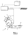
- the surface of the screened cylinder 5 comprises a multitude of cells allowing it to receive the ink which is brought to the rubber cylinder 8 using a pump not shown.
- the screened cylinder 5 allows in the course of its rotation an inking of the plate 3, which represents the pattern to be printed.
- the transfer system 7 allows the transport of each sheet in the direction of the arrow D to the nipping zone 9 between the counter-pressure cylinder 6 and the plate cylinder 2.
- the plate cylinder 2, the screen cylinder 5, the transfer system 7 and the back pressure cylinder 6 are each driven by an individual electronic servo motor, of the brushless motor type. All these motors are connected to an electronic circuit 10 for adjusting their respective speed.
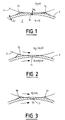
- FIGS. 1 to 3 show the behavior of the plate 3 during its passage through the contact area 11 between the screened cylinder 5 and the plate cylinder 2.
- the plate 3 being a rubber element, this compression results in a deformation of the rubber material.
- FIG. 1 shows the said deformation when the two screened cylinders 5 and plate holder 2 were stopped.
- the dotted line illustrates what would be the theoretical location of plate 3 in the absence of the screened cylinder 5.
- this defect is corrected by significantly increasing the peripheral linear speed of the screened cylinder 5 compared to that of the plate 3. This increase is substantially between 0.4 and 5%.
- the optimal value of this speed increase depends on a number of parameters, such as the printing rate that is required by the speed of rotation of the plate holder, the mechanical characteristics of plate 3 and the crushing of the plate.
- V1 is the peripheral linear speed of plate 3 and V2 that of the screened cylinder 5
- the optimal V2 / V1 ratio can be determined by successive tests by observing, for each test, the shape and the surface of the point d impression as the ratio increases beyond 1, said surface decreases then increases again. It is for this minimum surface, which should be close to the theoretical surface of the printing point, that the optimal V2 / V1 ratio is located.
- the deformation of the plate 3 is shown when the speed ratio V2 / V1 is equal to 1. This deformation results in the presence of a large bead 15 of rubber material upstream of the contact zone 11 and the disappearance or quasi-disappearance of the bead which previously existed downstream of said contact area 11. This deformation would be due to the friction forces brought into play on the surface of the plate 3 due to contact with the periphery of the screened cylinder 5 .
- the ovalization of the printing point can be explained by the correlative increase in the contact surface between the plate 3 and the screened cylinder 5.
- Electronic circuit 10 is programmed to automatically slave the position of the brushless motors which respectively rotate the plate cylinder 2, the screen cylinder 5 and the back pressure cylinder 6. This control is carried out so that the speed ratio is obtained in accordance with the process of the invention.
- This same electronic circuit 10 is connected to the system for adjusting the positioning of the different cylinders with respect to each other, which defines the pressure exerted between said cylinders during the passage of a part of the plate 3 between the screened cylinder 5 and the door cylinder -cliché 2, and on the other hand during the passage of the sheet to be printed 12 between the radiograph 3 and the back-pressure cylinder 6.
- This pressure, for a given radiograph 3 is characteristic of the crushing of said radiograph, c that is to say the reduction in thickness E c in the contact zone 11 (FIG. 1).
- FIG. 5 shows examples of a speed ratio value V2 / V1 as a function of the overwriting in millimeters of the photograph 3 for two printing rates, namely 4,000 sheets per hour and 8,000 sheets per liter. 'hour.
- the servo-control effected by the electronic circuit 10 of the rotational speeds is obtained by measuring one of the operating parameters of the drive motors of said cylinders. It can be a measurement of electrical current or a measurement of motor torque.
- the optimal speed ratio is that which corresponds to the minimum of the corresponding parameter.
- the control of the installation can be done automatically after a preset on the first sheets to be printed. To do this, it suffices to measure, for a speed ratio of 1, the variation of the intensity or of the motor torque during the passage of the plate between the screened cylinder 5 and the plate cylinder 2 or also during the passage of the sheet 12 between the plate 3 and the back pressure cylinder 6.
- the speed ratios are gradually increased while continuing to measure the variations in intensity or engine torque. The comparison of successive measurements makes it possible to determine the speed ratios which correspond to the minimum variations in intensity or in the engine torque.
- the three cylinders be equipped with independent brushless type motors or geared motors. They can be driven using a single motor with mechanical control, in particular by pinions or toothed belts. In this case it is necessary to determine an average value of the speed ratios, which make it possible to obtain a good print quality for a determined overwriting of photograph.
- the process and the installation are not limited to flexographic printing but can also be applied to offset printing.
Landscapes
- Inking, Control Or Cleaning Of Printing Machines (AREA)
- Printing Methods (AREA)
Claims (8)
- Verfahren zum Nacheinanderbedrucken von Bogen, beim dem ein Bogen bei seinem Hindurchtritt in der Druckzone zwischen einem ersten Druckzylinder (2), der an seinem Umfang ein Gummielement (3) aufweist, und einem Gegendruckzylinder (6), wobei die Druckfarbe bzw. Tinte zu dem ersten Druckzylinder (2) durch einen zweiten Druckfarbenzuführzylinder (5) gebracht wird, dadurch gekennzeichnet, daß zur Verminderung der Verformungen der Druckpunkte, es darin besteht, die Verhältnisse der linearen Umfangsgeschwindigkeiten des zweiten Druckfarbenzuführzylinders (5) und des Gegendruckzylinders (6) auf die lineare Umfangsgeschwindigkeit des Gummielements (3) des ersten Druckzylinders (2) auf Werte einzustellen, die konstant größer als 1 sind, enthalten in der Bandbreite von 1,004 bis 1,05.
- Verfahren nach Anspruch 1, dadurch gekennzeichnet, daß die Zylinder durch einen einzigen Motor mit mechanischer Steuerung in Drehung versetzt werden, insbesondere durch Ritzel oder Zahnriemen, wobei die Einstellung der Geschwindigkeitsverhältnisse auf einen Mittelwert eingestellt wird, für ein vorbestimmtes Quetschen des Druckstockes.
- Verfahren nach Anspruch 1, dadurch gekennzeichnet, daß, da die Zylinder unabhängig voneinander in Drehung versetzt werden, die Einstellung der Geschwindigkeitsverhältnisse für ein vorgegebenes Gummielement, in Abhängigkeit des Quetschens von diesem, automatisch eingestellt wird.
- Verfahren nach Anspruch 1, dadurch gekennzeichnet, daß, da die Zylinder unabhängig voneinander in Drehung versetzt werden, die Einstellung der Geschwindigkeitsverhältnisse automatisch geregelt wird, derart, daß der minimale elektrische Verbrauch für den Antriebsmotor des ersten Zylinders (2) erreicht wird.
- Verfahren nach einem der Ansprüche 1 bis 4, dadurch gekennzeichnet, daß zum Durchführen von Korrekturen der Drucklänge, bei Beibehalten einer guten Druckqualität, es darin besteht, Geschwindigkeitsverhältnisse einzustellen, und korrelativ das Zusammendrücken des Gummielements hinzuzufügen.
- Vorrichtung zum Durchführen des Verfahrens zum Nacheinanderbedrucken von Bogen, nach Anspruch 1, mit einem ersten Druckzylinder (2), der an seinem Umfang ein Gummielement (3) aufweist, einem zweiten Druckfarbenzubringzylinder (5) und einem dritten Gegendruckzylinder (6), wobei jeder zu druckende Bogen (12) aufeinanderfolgend bis in die Eingriffs- oder Quetschzone (9) zugeführt wird, zwischen dem ersten Druckzylinder (2) und dem Gegendruckzylinder (6), sowie mit Drehantriebseinrichtungen der drei vorgenannten Zylinder, dadurch gekennzeichnet, daß die Antriebseinrichtungen aus drei Motoren oder Motorgetrieben bestehen, die mechanisch unabhängig sind, wobei sie Einrichtungen zum Einstellen der Drehgeschwindigkeiten der drei Zylinder aufweist, die derart bestimmt sind, daß die linearen Umfangsgeschwindigkeitsverhältnisse des zweiten Zuführzylinders (5) und des Gegendruckzylinders (6) zur linearen Umfangsgeschwindigkeit des Gummielements (3) des ersten Druckzylinders (2) konstant Werte aufweisen, die größer als 1 sind, enthalten in der Bandbreite von 1,004 bis 1,05.
- Vorrichtung nach Anspruch 6, dadurch gekennzeichnet, daß sie Einstelleinrichtungen des Drucks des zweiten und dritten Zylinders gegen das Gummielement des ersten Druckzylinders aufweist, und daß die Einstelleinrichtungen des Druckes mit den Einstelleinrichtungen der Drehgeschwindigkeiten der Zylinder verbunden sind, derart daß sie die Einstellung der Geschwindigkeitsverhältnisse für ein vorgegebenes Gummielement in Abhängigkeit der Druckwerte der Zylinder gegeneinander oder mittels des zu bedruckenden Bogens ermöglichen.
- Vorrichtung nach Anspruch 6, dadurch gekennzeichnet, daß wenigstens der Antriebsmotor des ersten Druckzylinders (2) mit Einrichtungen zum Messen der Augenblicksintensität oder des Motormoments des Motors versehen ist, die ihrerseits über einen geeigneten elektronischen Schaltkreis mit den Einstelleinrichtungen der Drehgeschwindigkeit des zweiten und dritten Zylinders verbunden sind, und daß der elektronische Schaltkreis derart programmiert ist, daß er als Drehgeschwindigkeiten des zweiten und dritten Zylinders jene einstellt, die den minimalen Veränderungen der Intensität oder des Motormoments beim Hindurchbewegen des Gummielements (3) zwischen dem ersten und zweiten Zylinder einerseits, und zwischen dem ersten und dritten Zylinder andererseits entsprechen.
Applications Claiming Priority (2)
| Application Number | Priority Date | Filing Date | Title |
|---|---|---|---|
| FR9400093A FR2714632B1 (fr) | 1994-01-03 | 1994-01-03 | Procédé et installation pour l'impression feuille à feuille. |
| FR9400093 | 1994-01-03 |
Publications (3)
| Publication Number | Publication Date |
|---|---|
| EP0665104A1 EP0665104A1 (de) | 1995-08-02 |
| EP0665104B1 true EP0665104B1 (de) | 1996-08-21 |
| EP0665104B2 EP0665104B2 (de) | 2000-05-03 |
Family
ID=9458817
Family Applications (1)
| Application Number | Title | Priority Date | Filing Date |
|---|---|---|---|
| EP94490057A Expired - Lifetime EP0665104B2 (de) | 1994-01-03 | 1994-12-19 | Verfahren und Vorrichtung zum Nacheinander Bedrucken von Bogen |
Country Status (6)
| Country | Link |
|---|---|
| US (1) | US5542353A (de) |
| EP (1) | EP0665104B2 (de) |
| CN (1) | CN1062811C (de) |
| DE (1) | DE69400403T3 (de) |
| ES (1) | ES2093504T5 (de) |
| FR (1) | FR2714632B1 (de) |
Families Citing this family (12)
| Publication number | Priority date | Publication date | Assignee | Title |
|---|---|---|---|---|
| US6059705A (en) * | 1997-10-17 | 2000-05-09 | United Container Machinery, Inc. | Method and apparatus for registering processing heads |
| US6549745B2 (en) | 2001-02-16 | 2003-04-15 | Nexpress Solutions Llc | Method and apparatus for controlling overdrive in a frictionally driven system including a conformable member |
| US6556798B2 (en) | 2001-02-16 | 2003-04-29 | Donald S. Rimai | Method and apparatus for using a conformable member in a frictional drive |
| US20030100343A1 (en) * | 2001-05-18 | 2003-05-29 | Zourntos Takis C. | Communications system and method |
| DE102013109851A1 (de) * | 2013-09-09 | 2015-03-12 | Windmöller & Hölscher Kg | Verfahren für die Kontrolle der Rotationsgeschwindigkeit für eine Antriebsvorrichtung einer Druckwalze |
| DE102016015722B4 (de) | 2016-05-11 | 2023-06-22 | Koenig & Bauer Ag | Verfahren zum Erfassen und Einstellen von Parametern eines Bearbeitungsaggregats |
| DE102016208109A1 (de) * | 2016-05-11 | 2017-11-16 | Koenig & Bauer Ag | Verfahren zum Erfassen und Einstellen von Parametern eines Bearbeitungsaggregats |
| CN108032598A (zh) * | 2016-06-28 | 2018-05-15 | 海宁酷彩数码科技有限公司 | 一种改良的纸板压印机 |
| CN106113920B (zh) * | 2016-06-28 | 2019-03-12 | 义乌博众文化用品有限公司 | 自动纸板压印机 |
| CN108189535B (zh) * | 2016-06-28 | 2019-07-12 | 佛山市顺德区美安达彩印包装有限公司 | 一种纸板压印设备 |
| CA3034742A1 (en) * | 2016-08-23 | 2018-03-01 | B&R Industrial Automation GmbH | Method for controlling the drive of a machine |
| DE102021118033A1 (de) * | 2021-07-13 | 2023-01-19 | Koenig & Bauer Ag | Bearbeitungsmaschine sowie Verfahren zur Einstellung einer Drucklänge und/oder Bearbeitungslänge |
Family Cites Families (8)
| Publication number | Priority date | Publication date | Assignee | Title |
|---|---|---|---|---|
| US2022696A (en) * | 1932-06-17 | 1935-12-03 | Irving Trust Co | Printing machine |
| US2619901A (en) * | 1946-08-28 | 1952-12-02 | Harris Seybold Co | Impression length varying means for rotary offset printing machines |
| FR1341700A (fr) * | 1962-09-21 | 1963-11-02 | Etudes De Machines Speciales | Procédé et dispositif d'encrage pour machines d'impression à l'encre grasse |
| GB1052880A (de) * | 1962-12-19 | |||
| JPS55161652A (en) * | 1979-06-05 | 1980-12-16 | Mitsubishi Heavy Ind Ltd | Flexographic press |
| WO1981001266A1 (en) * | 1979-11-05 | 1981-05-14 | Dahlgren Mfg Co | Portable ink fountain |
| US4445433A (en) * | 1982-04-02 | 1984-05-01 | Menashe Navi | Method and apparatus for variable density inking |
| GB2146291B (en) † | 1983-09-14 | 1987-10-14 | Grace W R & Co | Rotary printing press |
-
1994
- 1994-01-03 FR FR9400093A patent/FR2714632B1/fr not_active Expired - Lifetime
- 1994-12-15 US US08/356,876 patent/US5542353A/en not_active Expired - Lifetime
- 1994-12-19 ES ES94490057T patent/ES2093504T5/es not_active Expired - Lifetime
- 1994-12-19 DE DE69400403T patent/DE69400403T3/de not_active Expired - Lifetime
- 1994-12-19 EP EP94490057A patent/EP0665104B2/de not_active Expired - Lifetime
- 1994-12-30 CN CN94113541A patent/CN1062811C/zh not_active Expired - Fee Related
Also Published As
| Publication number | Publication date |
|---|---|
| DE69400403T3 (de) | 2001-03-15 |
| US5542353A (en) | 1996-08-06 |
| CN1062811C (zh) | 2001-03-07 |
| FR2714632B1 (fr) | 1996-03-15 |
| DE69400403D1 (de) | 1996-09-26 |
| ES2093504T5 (es) | 2000-10-16 |
| FR2714632A1 (fr) | 1995-07-07 |
| EP0665104B2 (de) | 2000-05-03 |
| DE69400403T2 (de) | 1997-02-13 |
| ES2093504T3 (es) | 1996-12-16 |
| CN1125174A (zh) | 1996-06-26 |
| EP0665104A1 (de) | 1995-08-02 |
Similar Documents
| Publication | Publication Date | Title |
|---|---|---|
| EP0665104B1 (de) | Verfahren und Vorrichtung zum Nacheinander Bedrucken von Bogen | |
| EP0616886B1 (de) | Vorrichtung zum nacheinander Bedrucken von Bogen und die korrespondierende Druckstrasse | |
| FR2553032A1 (fr) | Presse d'impression flexographique a entrainement en prise directe et materiau d'emballage ainsi imprime | |
| FR2763278A1 (fr) | Procede pour regler l'encrage pour l'impression continue dans une presse rotative a imprimer | |
| FR2556280A1 (fr) | Presse d'impression a dispositif de reglage automatique de vitesse | |
| FR2550731A1 (fr) | Machine d'impression en couleurs a reglage de l'espacement des impressions | |
| EP0094320B1 (de) | Farbwerk und -verfahren für Druckmaschinen | |
| FR2518455A1 (fr) | Imprimeuse flexographique | |
| EP2277700B1 (de) | Verfahren zum Einstellen der Winkelgeschwindigkeit von Druckzylindern | |
| FR2882685A1 (fr) | Procede de commande ou de regulation d'un appareil de pliage d'une machine d'impression | |
| EP1938972A1 (de) | Offset-Druckerpresse mit Regulierung der Schneideklappe und entsprechendes Verfahren | |
| FR2550995A1 (fr) | Procede et dispositif de reglage assurant l'adaptation aux reperes et la conformite aux longueurs d'impression dans les imprimeuses flexographiques | |
| EP2343260B1 (de) | Verfahren zum Betrieb eines Schwertfalzwerks und ein Schwertfalzwerk | |
| EP1800863B1 (de) | Farbwerk und entsprechendes Einstellverfahren | |
| FR2804901A1 (fr) | Machine a imprimer offset equipee d'une commande de registres et procede pour son exploitation | |
| EP0557198A1 (de) | Vorrichtung und Verfahren zum Bestimmen der Kontaktposition zwischen zwei Teilen von denen mindestens eine mobil ist | |
| FR2885550A1 (fr) | Procede de conduite d'une machine d'impression | |
| FR2689060A1 (fr) | Procédé d'impression offset et dispositif correspondant. | |
| FR2910374A1 (fr) | Procede de commande d'une presse rotative et presse rotative | |
| EP0779861B1 (de) | Format variable rotationsdruckmaschine, insbesondere vom flexographischen typ | |
| EP1782953B1 (de) | Verfahren und Vorrichtung zum Einstellen der Farbzufuhrmenge eines Druckprodukts | |
| JP4337231B2 (ja) | 印字装置 | |
| FR2564781A1 (fr) | Systeme de montage de cliches sur des cylindres d'impression et procede de realisation de cliches | |
| CA1250788A (fr) | Correction automatique des ecarts de reperage pour l'impression rotographique | |
| FR2927837A1 (fr) | Unite d'impression pour presse rotative. |
Legal Events
| Date | Code | Title | Description |
|---|---|---|---|
| PUAI | Public reference made under article 153(3) epc to a published international application that has entered the european phase |
Free format text: ORIGINAL CODE: 0009012 |
|
| 17P | Request for examination filed |
Effective date: 19950526 |
|
| AK | Designated contracting states |
Kind code of ref document: A1 Designated state(s): CH DE ES FR GB IT LI |
|
| GRAG | Despatch of communication of intention to grant |
Free format text: ORIGINAL CODE: EPIDOS AGRA |
|
| GRAH | Despatch of communication of intention to grant a patent |
Free format text: ORIGINAL CODE: EPIDOS IGRA |
|
| 17Q | First examination report despatched |
Effective date: 19951228 |
|
| GRAH | Despatch of communication of intention to grant a patent |
Free format text: ORIGINAL CODE: EPIDOS IGRA |
|
| GRAA | (expected) grant |
Free format text: ORIGINAL CODE: 0009210 |
|
| AK | Designated contracting states |
Kind code of ref document: B1 Designated state(s): CH DE ES FR GB IT LI |
|
| REG | Reference to a national code |
Ref country code: CH Ref legal event code: NV Representative=s name: BOVARD AG PATENTANWAELTE |
|
| GBT | Gb: translation of ep patent filed (gb section 77(6)(a)/1977) |
Effective date: 19960821 |
|
| REF | Corresponds to: |
Ref document number: 69400403 Country of ref document: DE Date of ref document: 19960926 |
|
| ITF | It: translation for a ep patent filed | ||
| REG | Reference to a national code |
Ref country code: ES Ref legal event code: FG2A Ref document number: 2093504 Country of ref document: ES Kind code of ref document: T3 |
|
| PLBI | Opposition filed |
Free format text: ORIGINAL CODE: 0009260 |
|
| PLBF | Reply of patent proprietor to notice(s) of opposition |
Free format text: ORIGINAL CODE: EPIDOS OBSO |
|
| 26 | Opposition filed |
Opponent name: BOBST SA Effective date: 19970430 |
|
| PG25 | Lapsed in a contracting state [announced via postgrant information from national office to epo] |
Ref country code: FR Effective date: 19970829 |
|
| PLBF | Reply of patent proprietor to notice(s) of opposition |
Free format text: ORIGINAL CODE: EPIDOS OBSO |
|
| REG | Reference to a national code |
Ref country code: FR Ref legal event code: ST |
|
| PLBF | Reply of patent proprietor to notice(s) of opposition |
Free format text: ORIGINAL CODE: EPIDOS OBSO |
|
| PLAW | Interlocutory decision in opposition |
Free format text: ORIGINAL CODE: EPIDOS IDOP |
|
| PLAW | Interlocutory decision in opposition |
Free format text: ORIGINAL CODE: EPIDOS IDOP |
|
| PUAH | Patent maintained in amended form |
Free format text: ORIGINAL CODE: 0009272 |
|
| STAA | Information on the status of an ep patent application or granted ep patent |
Free format text: STATUS: PATENT MAINTAINED AS AMENDED |
|
| 27A | Patent maintained in amended form |
Effective date: 20000503 |
|
| AK | Designated contracting states |
Kind code of ref document: B2 Designated state(s): CH DE ES FR GB IT LI |
|
| REG | Reference to a national code |
Ref country code: CH Ref legal event code: AEN Free format text: MAINTIEN DU BREVET DONT L'ETENDUE A ETE MODIFIEE |
|
| GBTA | Gb: translation of amended ep patent filed (gb section 77(6)(b)/1977) | ||
| ITF | It: translation for a ep patent filed | ||
| REG | Reference to a national code |
Ref country code: ES Ref legal event code: DC2A Kind code of ref document: T5 Effective date: 20000731 |
|
| REG | Reference to a national code |
Ref country code: DE Ref legal event code: 8570 |
|
| REG | Reference to a national code |
Ref country code: GB Ref legal event code: IF02 |
|
| REG | Reference to a national code |
Ref country code: CH Ref legal event code: PFA Owner name: CUIR (S.A.) Free format text: CUIR (S.A.)#14, RUE DU PONT DE GRES#F-62220 CARVIN (FR) -TRANSFER TO- CUIR (S.A.)#14, RUE DU PONT DE GRES#F-62220 CARVIN (FR) |
|
| PGFP | Annual fee paid to national office [announced via postgrant information from national office to epo] |
Ref country code: ES Payment date: 20121219 Year of fee payment: 19 Ref country code: IT Payment date: 20121217 Year of fee payment: 19 Ref country code: GB Payment date: 20121219 Year of fee payment: 19 |
|
| PGFP | Annual fee paid to national office [announced via postgrant information from national office to epo] |
Ref country code: CH Payment date: 20131212 Year of fee payment: 20 Ref country code: DE Payment date: 20131210 Year of fee payment: 20 |
|
| GBPC | Gb: european patent ceased through non-payment of renewal fee |
Effective date: 20131219 |
|
| PG25 | Lapsed in a contracting state [announced via postgrant information from national office to epo] |
Ref country code: GB Free format text: LAPSE BECAUSE OF NON-PAYMENT OF DUE FEES Effective date: 20131219 |
|
| REG | Reference to a national code |
Ref country code: DE Ref legal event code: R071 Ref document number: 69400403 Country of ref document: DE |
|
| REG | Reference to a national code |
Ref country code: CH Ref legal event code: PL |
|
| REG | Reference to a national code |
Ref country code: ES Ref legal event code: FD2A Effective date: 20150327 |
|
| PG25 | Lapsed in a contracting state [announced via postgrant information from national office to epo] |
Ref country code: ES Free format text: LAPSE BECAUSE OF NON-PAYMENT OF DUE FEES Effective date: 20131220 |
|
| PG25 | Lapsed in a contracting state [announced via postgrant information from national office to epo] |
Ref country code: IT Free format text: LAPSE BECAUSE OF NON-PAYMENT OF DUE FEES Effective date: 20131219 |