EP0666647A1 - Procédé et circuit pour commander des commutateurs semi-conducteurs montés en série - Google Patents
Procédé et circuit pour commander des commutateurs semi-conducteurs montés en série Download PDFInfo
- Publication number
- EP0666647A1 EP0666647A1 EP95810023A EP95810023A EP0666647A1 EP 0666647 A1 EP0666647 A1 EP 0666647A1 EP 95810023 A EP95810023 A EP 95810023A EP 95810023 A EP95810023 A EP 95810023A EP 0666647 A1 EP0666647 A1 EP 0666647A1
- Authority
- EP
- European Patent Office
- Prior art keywords
- switch
- pulse
- control
- voltage limiting
- voltage
- Prior art date
- Legal status (The legal status is an assumption and is not a legal conclusion. Google has not performed a legal analysis and makes no representation as to the accuracy of the status listed.)
- Granted
Links
- 238000000034 method Methods 0.000 title claims abstract description 39
- 239000004065 semiconductor Substances 0.000 title claims description 124
- 230000001934 delay Effects 0.000 claims abstract description 5
- 230000000670 limiting effect Effects 0.000 claims description 82
- 230000004044 response Effects 0.000 claims description 14
- 238000001514 detection method Methods 0.000 claims description 13
- 230000008569 process Effects 0.000 claims description 8
- 230000003111 delayed effect Effects 0.000 claims description 7
- 230000001105 regulatory effect Effects 0.000 claims description 7
- 230000001276 controlling effect Effects 0.000 claims description 6
- 230000008859 change Effects 0.000 description 2
- 230000006870 function Effects 0.000 description 2
- 238000004549 pulsed laser deposition Methods 0.000 description 2
- 230000009467 reduction Effects 0.000 description 2
- 230000002441 reversible effect Effects 0.000 description 2
- 101150069031 CSN2 gene Proteins 0.000 description 1
- -1 Dsn1 or Rsn2 Proteins 0.000 description 1
- 101150106478 GPS1 gene Proteins 0.000 description 1
- 230000004913 activation Effects 0.000 description 1
- 230000008901 benefit Effects 0.000 description 1
- 101150055601 cops2 gene Proteins 0.000 description 1
- 230000001066 destructive effect Effects 0.000 description 1
- 238000011161 development Methods 0.000 description 1
- 230000018109 developmental process Effects 0.000 description 1
- 238000006073 displacement reaction Methods 0.000 description 1
- 230000005611 electricity Effects 0.000 description 1
- 238000011156 evaluation Methods 0.000 description 1
- 238000005259 measurement Methods 0.000 description 1
- 230000003287 optical effect Effects 0.000 description 1
- 230000002028 premature Effects 0.000 description 1
- 230000001681 protective effect Effects 0.000 description 1
- 230000009993 protective function Effects 0.000 description 1
- 230000002829 reductive effect Effects 0.000 description 1
- 230000000717 retained effect Effects 0.000 description 1
Images


Classifications
-
- H—ELECTRICITY
- H03—ELECTRONIC CIRCUITRY
- H03K—PULSE TECHNIQUE
- H03K17/00—Electronic switching or gating, i.e. not by contact-making and –breaking
- H03K17/08—Modifications for protecting switching circuit against overcurrent or overvoltage
- H03K17/081—Modifications for protecting switching circuit against overcurrent or overvoltage without feedback from the output circuit to the control circuit
- H03K17/0814—Modifications for protecting switching circuit against overcurrent or overvoltage without feedback from the output circuit to the control circuit by measures taken in the output circuit
- H03K17/08148—Modifications for protecting switching circuit against overcurrent or overvoltage without feedback from the output circuit to the control circuit by measures taken in the output circuit in composite switches
-
- H—ELECTRICITY
- H03—ELECTRONIC CIRCUITRY
- H03K—PULSE TECHNIQUE
- H03K17/00—Electronic switching or gating, i.e. not by contact-making and –breaking
-
- H—ELECTRICITY
- H03—ELECTRONIC CIRCUITRY
- H03K—PULSE TECHNIQUE
- H03K17/00—Electronic switching or gating, i.e. not by contact-making and –breaking
- H03K17/08—Modifications for protecting switching circuit against overcurrent or overvoltage
- H03K17/082—Modifications for protecting switching circuit against overcurrent or overvoltage by feedback from the output to the control circuit
- H03K17/0828—Modifications for protecting switching circuit against overcurrent or overvoltage by feedback from the output to the control circuit in composite switches
-
- H—ELECTRICITY
- H03—ELECTRONIC CIRCUITRY
- H03K—PULSE TECHNIQUE
- H03K17/00—Electronic switching or gating, i.e. not by contact-making and –breaking
- H03K17/10—Modifications for increasing the maximum permissible switched voltage
- H03K17/102—Modifications for increasing the maximum permissible switched voltage in field-effect transistor switches
-
- H—ELECTRICITY
- H03—ELECTRONIC CIRCUITRY
- H03K—PULSE TECHNIQUE
- H03K17/00—Electronic switching or gating, i.e. not by contact-making and –breaking
- H03K17/10—Modifications for increasing the maximum permissible switched voltage
- H03K17/107—Modifications for increasing the maximum permissible switched voltage in composite switches
Definitions
- the invention relates to a method for controlling semiconductor switches of a series circuit according to the preamble of claim 1 and to a circuit arrangement for performing this method.
- semiconductor switches such as power transistors, MOSFET transistors, IGBTs (Insulated Gate Bipolar Transistor) and GTOs (Gate Turn-Off-Thyristor) - have a limited maximum reverse voltage. If higher voltages are switched, it is necessary to connect the semiconductor switches in series. The switched DC voltage exceeds the maximum permitted voltage of each of the series-connected semiconductor switches. Accordingly, a protective device must ensure that the maximum permissible voltage at each semiconductor switch is not exceeded, regardless of the operating state. This is the case when the DC voltage is evenly distributed across the individual open semiconductor switches. A uniform or symmetrical voltage distribution across the switched-off semiconductor switches is usually achieved in stationary operation by means of balancing resistors.
- the teaching can also be gathered of measuring the stationary voltages of the semiconductor switch and regulating them to a predetermined setpoint by shifting the switching edges. Doing so Proceed in such a way that if the semiconductor voltage was too high at the last shutdown, the next shutdown edge is delayed by a controller. If the voltage of the previous shutdown was too low, the shutdown edge is shifted to an earlier point in time.
- a method for protecting series-connected semiconductor switches according to the preamble of claim 1 is also known from the prior art, for the implementation of which a voltage limiting device is assigned to each semiconductor switch. At high voltages on the semiconductor switch that exceed a certain value and thereby activate the voltage limiting device, a large current flows through the voltage limiting device at a high voltage. This results in pulse-like electrical losses in the voltage limiting device, which considerably shorten the service life of the voltage limiting device in the case of repeated switching operations.
- the object of the invention is to provide a method and a circuit arrangement for controlling semiconductor switches of a series circuit, by means of which the semiconductor switches are reliably and easily protected in any operating state.
- the power losses of the voltage limiting devices assigned to the individual semiconductor switches are detected by a control device, which generates modified control pulses for each semiconductor switch from a common control pulse, by means of these modified control pulses the voltage distribution across the semiconductor switches is equalized and, as a result, the power loss of the voltage limiting devices is regulated to a minimum .
- the common control pulse is modified in such a way that it is shifted by the control device until the respective voltage limiting device no longer responds.
- the switching of the semiconductor switches becomes symmetrical and the semiconductor voltages remain below the response voltage of the corresponding voltage limiting devices. Since the response voltage of the individual voltage limiting devices is not constantly exceeded, the lifespan of their components increases. Combined protection of the series circuit is thus ensured according to the invention in that the corresponding semiconductor switch is first protected against overload by means of the passive voltage limiting device and then the voltage limiting device itself by means of the relief control. As a result, the function of the series connected Semiconductor switch guaranteed in every operating state.
- the protective function is performed by the respective passive voltage limiting device. Slow changes in the switching behavior of the semiconductor switches or re-balancing are corrected by the active control described above, thereby relieving the voltage limiting device.
- the method according to the invention enables semiconductor switches such as IGBTs, GTOs or transistors with different switching times and without preselection to be connected in series.
- Another advantage of the invention is that the circuit arrangement can be realized by small and inexpensive components as voltage limiting devices with low power dissipation, such as zener diodes or varistors. At the same time, the life of the circuit arrangement increases because the components of the voltage limiting device are relieved.
- the method according to the invention also enables the advantageous use of fast-switching semiconductor switches in the high-voltage range - such as IGBT's.
- a circuit arrangement according to claim 18 is preferably provided for carrying out the method according to the invention.
- each switch consists of at least two series-connected semiconductor switches 10 and 11, which are designed here as IGBTs with anti-parallel diodes.
- Other non-latching semiconductor switches such as, for example, bipolar transistors, can also serve as semiconductor switches.
- the non-latching semiconductor switches used here are known to be switched off by a small control current after being switched on.
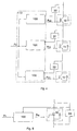
- FIG. 3 it has three series-connected semiconductor switches 10, 11 and 12, which belong to one of the switches mentioned above.
- a voltage limiting device 30, 31 and 32 is provided for each of the non-latching semiconductor switches 10, 11 and 12, which is connected between the collector and the control electrode of the semiconductor switch.
- All voltage limiting devices 30, 31 and 32 are connected to a control device 110 for measurement purposes. This is in turn connected to an external control pulse generator (not shown in FIG. 3) in order to generate modified control pulses P20, P21 and P22 for the individual semiconductor switches from a control pulse P1 common to all semiconductor switches.
- the circuit arrangement in FIG. 3 functions in the manner described below.
- control device 110 consists of three independent control devices 100, 101 and 102, which are assigned to the corresponding semiconductor switches 10, 11 and 12.
- each semiconductor switch is a snap-in type using the example of the semiconductor switch 10
- the corresponding voltage limiting device is connected using the example of the voltage limiting device 30 between the anode and cathode of the semiconductor switch 10.
- Various sizes can be used as a measure of the power loss of the voltage limiting devices 30, 31 and 32 to be detected by the control device 110 or by the individual control devices 100, 101 and 102.
- a size e.g. the time area of the current can be detected by the respective voltage limiting device.
- This time area multiplied by the voltage of the voltage limiting device gives the energy loss and is therefore proportional to the power loss of the voltage limiting device at a certain switching frequency. Because the response voltage of the voltage limiting device is constant, the current time area is representative of the power loss.
- the time area of the current representative of the power loss is itself proportional to the amplitude of the current and the duration of the current flow in the voltage limiting device. Accordingly, only the amplitude of the current I s through the semiconductor switches 10, 11 and 12 can be detected by the control device or device, because the amplitude is thus proportional to the power loss of the voltage limiting device. Such a procedure is particularly well suited for a binary evaluation of the power loss of the voltage limiting device. For the implementation of a binary amplitude measuring element in the control device or device, only one comparator is required which, when a certain amplitude value is exceeded generates a pulse (I pulse). A binary current flow duration measuring element generates a pulse of constant length (I-pulse), which indicates the presence of a current in the voltage limiting device.
- the duration of the current I s through the semiconductor switches 10, 11 and 12 can be detected by the control device or device, because the duration is also proportional to the power loss of the voltage limiting device.
- a current flow duration measuring element in the control device or device, only one comparator is needed, which generates a pulse during the current flow through the voltage limiting device. The length of the pulse is proportional to the power loss that arises.
- the temperature of the elements of the voltage limiting device is also representative of the power loss of the latter. This temperature can be recorded electronically and used as the basis for the control, although the thermal time constant of these elements must be taken into account.
- a snubber can be connected in parallel with each semiconductor switch to limit the voltage peaks when the semiconductor switch current is switched off.
- the first control device 100 is coupled to the other control devices 101 and 102.
- the semiconductor switch 10, to which the first control device 100 belongs serves as a reference switch or master, the other semiconductor switches 31 and 32 being referred to as slaves are.
- This circuit arrangement ensures the following procedure:
- the control device 100 of the master 10 shifts or delays the common control pulse P20 by a constant initial time value which is greater than the maximum asymmetry times of the semiconductor switch 10 and the signal electronics. The same delay is loaded as the initial value of the control pulses P21 and P22 of the slaves 11 and 12.
- the control device 100 does not change the initial values of the pulse shift of the master 10.
- the control devices 101 and 102 of the slaves 11 and 12 shift the control pulses P21 and P22 of the slaves 11 so that the power losses of the voltage limiting devices 31 and 32 are regulated to a minimum or to zero become. If the master 10 switches off too slowly and the voltage limiting device 30 intervenes, the control device 100 generates the signal P a , which indicates the power loss of the voltage limiting device 30 when switching off.
- the signal P a is passed to the other control devices 101 and 102 and leads to the same increase in the pulse delay of the switching-off edges. This ensures that the switching off of the master 10 is faster compared to the switching off of the slaves 11 and 12 without changing the delay of the modified control pulse P20 on the master 10.
- the control device 100 If the master 10 switches on too quickly and the voltage limiting device 30 intervenes, the control device 100 generates the signal P e , which indicates the power loss of the voltage limiting device 30 when switched on.
- the signal P e is passed to the other control devices 101 and 102 and leads to an equal reduction in the pulse delay of the switch-on edges. It is thereby achieved that the switching on of the master 10 compared to the switching on of the slaves 11 and 12 is slower without changing the delay of the modified control pulse P20 on the master 10.
- a fifth exemplary embodiment of the circuit arrangement shown in FIG. 7 corresponds to the previous exemplary embodiment, in which a short-circuit element 90, 91 and 92, respectively, connected in parallel to each of the semiconductor switches 10, 11 and 12 is provided. If this circuit arrangement leads to failure of one or more of the series-connected semiconductor switches 10, 11 and 12, so that the electrical route for the switch current I s is interrupted, the respective short-circuit element 90, 91 and 92 takes over the current flow for a limited amount Time and prevents a destructive electrical discharge (arc) from occurring.
- the short-circuit element itself has a voltage response threshold which is greater than the response threshold of the corresponding voltage limiting device.
- the respective short-circuit element 90, 91 or 92 only intervenes when the voltage limitation by the voltage limiting device 30, 31 or 32 and the power control by the control device 100, 101 or 102 do not work because the non-latching semiconductor switch 10, 11 or 12 has failed, interrupting the current flow. If the voltage limiting device is connected between the anode and cathode of a latching semiconductor switch, as shown in FIG. 5, the voltage limiting device takes over the current and a short-circuit element is not absolutely necessary.
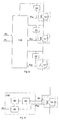
- modified control pulses P20, P21 and P22 are generated by the common control device for all semiconductor switches 10, 11 and 12.
- the voltage of each semiconductor switch is adjusted to a voltage setpoint S 1, which is less than the response voltage of the respective voltage limiting device is.
- the voltage regulator 110 regulates the semiconductor switch voltage to a desired value S 1, which is smaller than the response voltage of the voltage limiting devices, the voltage limiting devices do not respond in continuous operation. Only as long as the voltage control has not yet corrected the asymmetries by shifting the edge of the pulse P 1, do the voltage limiting devices 30, 31, 32 intervene. The adjustment process only takes a few switching periods. This method therefore offers indirect protection of the voltage limiting devices. The prerequisite for this is that the voltage setpoint S 1 is sufficiently smaller than the response voltage of the voltage limiting devices.
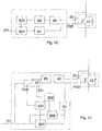
- a seventh exemplary embodiment shown in FIG. 9 shows a possible structure of the control device 100, which can also be used analogously with the other semiconductor switches.
- This circuit arrangement has a voltage limiting device 30 designed as a Zener diode, which is connected between the collector and the control electrode of the semiconductor switch 10.
- a power loss detection device 40 is connected to the zener diode 10, with which the flow of a current in the tens diode is detected and is reported to a controller 50 with a pulse delay 60.
- the controller 50 forms a delay on the basis of the actual values measured on the Zener diode 10, which accordingly delays the external control pulse P 1 and thereby forms a modified control pulse P 2 0.
- FIG. 10 shows a special embodiment of the circuit arrangement in FIG. 9, in which the detection device 40 is a binary actual value detection device.
- the binary actual value detection device 40 generates one pulse per switch-off process (I pulse) when a current flows through the voltage limiting device 30 flows when switched off.
- the I-pulse is transmitted through a galvanic isolating element 80 (optocoupler) to a digital switch-off controller 501, which increases the delay for the switch-off control pulse edge by a time quantum after each I-pulse.
- a modified control pulse P20 is formed, which reaches the control input of the semiconductor switch 10 through a galvanic isolating element 81.
- FIG. 11 shows a further special embodiment of the circuit arrangement in FIG. 9, in which the detection device 40 is also a binary actual value detection device, which generates one pulse per switching operation (I pulse) if a current flows through the voltage limiting device when the device is switched off.
- the I-pulse is transmitted through a galvanic isolating element 80 to a switch 41, which is controlled by the control pulse P 1 so that the I-pulses of switching on to a digital switch-on controller 502 and the I-pulses of switching off to a digital switch-off Controller 501.
- the outputs of the switch-on controller 502 and the switch-off controller 501 each act on a digital switch-on pulse delay 602 and a digital switch-off pulse delay 601, so that a delayed control pulse P20 is thereby formed.
- the delayed control pulse P20 then reaches the control input of the semiconductor switch 10 via a galvanic isolating element 81.
- a binary voltage measuring element can additionally be provided, which signals the falling below a predetermined semiconductor switch voltage setpoint after each switch-off with a pulse (U-pulse) to the digital switch-off controller 501, thereby ensuring a reduction in the delay of the switch-off edge of the control pulse P 1 to be modified. This ensures that the voltage of the semiconductor switch this Not less than the value.
- the voltage regulator and the power loss regulator of the voltage limiting device operate in parallel. If the semiconductor switch voltage is too low in the switched-off state, the switch-off pulse edge is prematurely caused by the voltage regulator, so that the semiconductor switch voltage rises the next time the switch is switched off.
- the voltage regulator and the power dissipation controller of the voltage limiting device therefore operate like a hysteresis control of the voltage.
- FIG. 12 shows a tenth embodiment in which a control device 200 is additionally provided in addition to the circuit arrangement shown in FIG. 4.
- the control device 200 detects the states of an overcurrent, an overvoltage and a diode asymmetry in the operating states described below.
- the current at which all voltage limiting devices respond is the maximum permitted switch current I smax .
- the control device 200 detects this state and generates an overcurrent signal I max .
- the applied DC voltage U dc can permanently exceed the maximum permitted value Udcmax.
- This maximum voltage is divided symmetrically via the individual semiconductor switches 10, 11 and 12, the response thresholds of all voltage limiting devices 30, 31 and 32 being exceeded.
- This state is stationary, ie it lasts as long as the maximum voltage U dcmax is present.
- This state in which no switch current I s flows, can only be ended by switching off the excessively high voltage Udc. Such a condition permanently destroys the voltage limiting devices 30, 31 and 32 and the semiconductor switches 10, 11 and 12.
- the corresponding voltage limiting device intervenes and the semiconductor switch connected in parallel with the relevant diode is switched on, so that the latter becomes conductive and limits the diode voltage.
- the control device 200 serves here to generate a diode asymmetry signal D max in this case.
- the overcurrent signal I max , overvoltage signal U max and diode asymmetry signal supplied by the control device 200 D max can be used, for example, for additional control in such a circuit arrangement according to FIG. 12, in which the control devices are designed according to FIG. 11 and an actual value filter is connected between the switch 41 and the controllers 501, 502.
- the actual value filter is controlled by the overcurrent signal I max or by the overvoltage signal U max or by the diode asymmetry signal D max so that, in the above-described conditions, which lead to the generation of these signals actual values of the current flowing through the corresponding voltage limiting device measured by the detection device 40 are filtered out by means of the actual value filter.
- a module of the semiconductor switches 10, 11 each comprises an IGBT and a free-wheeling diode.
- RCD snubbers protect the modules from overvoltage peaks when the load current is switched off.
- the snubbers are formed by the elements Rsn1, Csn1, Dsn1 or Rsn2, Csn2, Dsn2.
- the balancing resistors Rsym1, Rsym2 ensure the stationary voltage distribution of the series connection.
- the short-circuit elements are designed as avalange diodes Dk1, Dk2 or as varistors. These take over the current flow when the modules fail and the module voltage exceeds the response threshold of the voltage limiting devices and the higher response threshold of these short-circuit elements Dk1, Dk2.
- the voltage limiting devices of the master and the slave are designed as a Zener diode Dz10, Dz11.
- the flow of electricity through each Zener diode Dz10, Dz11 is detected and generates one pulse (I pulse).
- the differential element Dif10 or Dif11 is responsible for this.
- the I pulse is transmitted through the optocoupler Ok10 or Ok12 to the control device of the master or the slave.
- the digital components of the control devices 100, 101 are integrated in a PLD (Programmable Logic Device).
- the signals P a and P e are generated by the control device 100 of the master 10 and are further routed internally in the PLD to the slave controller 101.
- these signals P a , P e are carried out from the PLD and can be used to control further slave PLDs. This means that any number of slave PLDs can be cascaded.
- the signal P e defines whether the switch-on edges are changed, the signal P a indicates whether the switch-off edges are changed.
- the signal P a or P e consists of two bits; one bit indicates that the corresponding edges are premature and the second bit indicates that the edges are delayed.
- the calculated delay times are stored in the EEPROM (Erasable Electrical Programable Read Only Memory) and are retained after a power failure.
- the digitized delay times are loaded into the delay blocks for switching on and off of the master in0 V, V of0 and in the delay blocks for switching on and off of the slave Veinl, V OFF1, which allow delays in the nanosecond range.
- the PLD loads the newly calculated times after each pulse.
- the central control signal P1 is delayed by the delay elements V in1, V OUT1, V in0, V out0 and the modified control signals P20, P21 are forwarded by the optical coupler Ok11, Ok13 to the drivers Drv10 Drv11.
- the amplified signals pass through the gate resistors Rg1, Rg2 to the gates of the IGBTs.
- the PLD also generates the binary signals I max if the I pulses of all voltage limiting devices respond while the load current is switched off by the IGBTs. If all I-pulses are generated in the de-energized state, the signal U max is generated. The signal D max (diode asymmetry) is then generated if all I pulses are present and the load current I s is switched off by the freewheeling diodes, ie if the load current in FIG. 13 is directed to plus. The load current is detected by the current sensor I, which indicates the current direction by means of the binary signal I sign .
- the error states which correspond to the signals U max , I max , D max , are stored in an error register of the PLD. The external activation of the Reset signal causes the error states and the U max , I max and D max signals to be reset.
Landscapes
- Electronic Switches (AREA)
- Power Conversion In General (AREA)
- Semiconductor Integrated Circuits (AREA)
- Control Of Electrical Variables (AREA)
Applications Claiming Priority (2)
| Application Number | Priority Date | Filing Date | Title |
|---|---|---|---|
| DE4403941 | 1994-02-08 | ||
| DE4403941A DE4403941C2 (de) | 1994-02-08 | 1994-02-08 | Verfahren und Schaltungsanordnung zur Ansteuerung von Halbleiterschaltern einer Reihenschaltung |
Publications (2)
| Publication Number | Publication Date |
|---|---|
| EP0666647A1 true EP0666647A1 (fr) | 1995-08-09 |
| EP0666647B1 EP0666647B1 (fr) | 2001-09-19 |
Family
ID=6509781
Family Applications (1)
| Application Number | Title | Priority Date | Filing Date |
|---|---|---|---|
| EP95810023A Expired - Lifetime EP0666647B1 (fr) | 1994-02-08 | 1995-01-13 | Procédé et circuit pour commander des commutateurs semi-conducteurs montés en série |
Country Status (9)
| Country | Link |
|---|---|
| US (1) | US5616970A (fr) |
| EP (1) | EP0666647B1 (fr) |
| JP (1) | JP3565933B2 (fr) |
| KR (1) | KR100353293B1 (fr) |
| CN (1) | CN1127213C (fr) |
| AT (1) | ATE205978T1 (fr) |
| CA (1) | CA2140575C (fr) |
| DE (2) | DE4403941C2 (fr) |
| ES (1) | ES2164749T3 (fr) |
Cited By (8)
| Publication number | Priority date | Publication date | Assignee | Title |
|---|---|---|---|---|
| EP0785625A3 (fr) * | 1996-01-16 | 1999-06-16 | Cegelec Controls Ltd. | Montage de protection pour un dispositif de commutation |
| DE19838389C1 (de) * | 1998-08-24 | 2000-03-09 | Siemens Ag | Verfahren und Vorrichtung zur Steuerung eines abschaltbaren Stromrichterventils mit der Reihenschaltzahl Zwei oder größer |
| WO2001006654A1 (fr) * | 1999-07-15 | 2001-01-25 | Alstom Belgium S.A. | Procede de protection des semi-conducteurs de puissance d'un convertisseur de puissance et convertisseur mettant en oeuvre ce procede |
| FR2826803A1 (fr) * | 2001-06-27 | 2003-01-03 | Mitsubishi Electric Corp | Dispositif a semiconducteur |
| EP0927463A4 (fr) * | 1996-09-23 | 2005-10-19 | Eldec Corp | Commutateur haute tension a semi-conducteur et alimentation a decoupage |
| CN100446419C (zh) * | 2003-04-24 | 2008-12-24 | 三菱电机株式会社 | 半导体器件 |
| CN108092493A (zh) * | 2017-12-26 | 2018-05-29 | 南京工程学院 | 一种SiC MOSFET串联电路 |
| EP4025450A4 (fr) * | 2019-09-05 | 2023-10-04 | Scania CV AB | Disjoncteur électronique doté d'une protection à déclenchement automatique pour un véhicule et procédé associé |
Families Citing this family (26)
| Publication number | Priority date | Publication date | Assignee | Title |
|---|---|---|---|---|
| SE9500761D0 (sv) * | 1995-03-02 | 1995-03-02 | Abb Research Ltd | Skyddskrets för seriekopplade krafthalvledare |
| US5828112A (en) * | 1995-09-18 | 1998-10-27 | Kabushiki Kaisha Toshiba | Semiconductor device incorporating an output element having a current-detecting section |
| DE19539554C1 (de) * | 1995-10-13 | 1997-01-23 | Daimler Benz Ag | Schaltungsanordnung zur Symmetrierung der Spannungsaufteilung einer Reihenschaltung gate-gesteuerter Leistungshalbleiterschalter im Spannungszwischenkreis-Stromrichter |
| US6489990B1 (en) * | 1995-11-30 | 2002-12-03 | Koninklijke Philips Electronics N.V. | Highlight compensation apparatus for monochrome cameras |
| US5712587A (en) * | 1996-04-08 | 1998-01-27 | Electric Power Research Institute, Inc. | Apparatus and method for simultaneously deactivating series-connected switching devices |
| CA2232199C (fr) * | 1997-04-22 | 2000-02-22 | Kabushiki Kaisha Toshiba | Convertisseur de puissance avec elements de commutation de commande en tension |
| JP3447949B2 (ja) | 1998-03-31 | 2003-09-16 | 株式会社東芝 | 絶縁ゲート型半導体素子のゲート駆動回路、電力変換装置 |
| US6424035B1 (en) * | 1998-11-05 | 2002-07-23 | Fairchild Semiconductor Corporation | Semiconductor bilateral switch |
| DE10146900A1 (de) * | 2001-09-24 | 2003-04-10 | Abb Research Ltd | Schaltungsanordnung und Verfahren zur potentialgetrennten Ansteuerung in Serie geschalteter, abschaltbarer Halbleiterschaltelemente |
| JP3791400B2 (ja) * | 2001-11-22 | 2006-06-28 | 三菱電機株式会社 | 半導体装置 |
| FR2857176B1 (fr) * | 2003-07-02 | 2005-09-02 | Inst Nat Polytech Grenoble | Dispositif de protection pour composant electronique et circuit integre |
| DE10351873B4 (de) * | 2003-11-06 | 2012-07-26 | Pilz Gmbh & Co. Kg | Vorrichtung und Verfahren zum fehlersicheren Abschalten eines induktiven Verbrauchers |
| JP4823024B2 (ja) * | 2006-11-09 | 2011-11-24 | 株式会社東芝 | レベル変換回路 |
| US7508096B1 (en) * | 2007-09-20 | 2009-03-24 | General Electric Company | Switching circuit apparatus having a series conduction path for servicing a load and switching method |
| US8869962B2 (en) | 2010-09-20 | 2014-10-28 | Schaeffler Technologies AG & Co. KG | Wheel spindle drive element |
| EP2445110B1 (fr) * | 2010-10-22 | 2014-05-14 | ABB Research Ltd | Unité de commande de porte pour dispositif de commutation électrique |
| US9071169B2 (en) * | 2011-02-18 | 2015-06-30 | Ge Hybrid Technologies, Llc | Programmable gate controller system and method |
| DE102011079545A1 (de) * | 2011-07-21 | 2013-01-24 | Siemens Aktiengesellschaft | Schaltungsanordnung mit einem Halbleiterschalter und einer zugehörigen Ansteuerschaltung |
| GB201311997D0 (en) * | 2013-07-04 | 2013-08-21 | Amantys Ltd | Synchronising parallel power switches |
| JP6066867B2 (ja) * | 2013-08-27 | 2017-01-25 | 三菱電機株式会社 | 駆動回路および半導体装置 |
| US9515651B2 (en) | 2014-06-19 | 2016-12-06 | Triune Ip Llc | Galvanically isolated switch system |
| EP3081948A1 (fr) * | 2015-04-15 | 2016-10-19 | General Electric Technology GmbH | Mesure et equilibrage de courant |
| GB2542805A (en) * | 2015-09-30 | 2017-04-05 | General Electric Technology Gmbh | Semiconductor switching string |
| JP7565079B2 (ja) * | 2017-09-07 | 2024-10-10 | ヴィスアイシー テクノロジーズ リミテッド | 高電圧高速スイッチング装置 |
| CN109525229A (zh) * | 2017-09-18 | 2019-03-26 | 通用电气公司 | 用于控制串联功率开关器件之电压平衡的方法和系统 |
| EP3512083B1 (fr) | 2018-01-12 | 2023-08-23 | ABB Schweiz AG | Détermination et compensation de retard de commutation de transistor de puissance |
Citations (9)
| Publication number | Priority date | Publication date | Assignee | Title |
|---|---|---|---|---|
| JPS512571A (ja) * | 1974-06-27 | 1976-01-10 | Braun Ag | Kaenkaikoheisabutaojusurugasuraitaa |
| US3943427A (en) * | 1974-07-02 | 1976-03-09 | Jury Georgievich Tolstov | Apparatus for protecting the thyristors of a high-voltage controlled converter from overvoltage |
| DE2519396A1 (de) * | 1975-04-30 | 1976-11-04 | Siemens Ag | Schaltungsanordnung zum schutz von thyristoren |
| DE2852943A1 (de) * | 1978-12-07 | 1980-06-12 | Licentia Gmbh | Anordnung mit einem verzoegerungsbehafteten halbleiterschalter |
| JPS5843175A (ja) * | 1981-09-04 | 1983-03-12 | Hitachi Ltd | サイリスタの故障検出装置 |
| EP0202962A1 (fr) * | 1985-04-17 | 1986-11-26 | Jeumont-Schneider Industrie | Procédé de commande de l'instant d'ouverture d'au moins deux interrupteurs en série et circuit logique correspondant |
| EP0288421A2 (fr) * | 1987-04-24 | 1988-10-26 | Licentia Patent-Verwaltungs-GmbH | Symétrisation des courants commutés par des semi-conducteurs commandés par la porte et disposés en parallèle |
| EP0288422A2 (fr) * | 1987-04-24 | 1988-10-26 | Licentia Patent-Verwaltungs-GmbH | Equilibrage de la répartition des tensions lors de la coupure d'un circuit-série de semi-conducteurs commandés par la porte |
| EP0575131A1 (fr) * | 1992-06-15 | 1993-12-22 | Kabushiki Kaisha Toshiba | Appareil de commande pour un convertisseur au thyristor |
Family Cites Families (8)
| Publication number | Priority date | Publication date | Assignee | Title |
|---|---|---|---|---|
| JPS546758A (en) * | 1977-06-17 | 1979-01-19 | Fuji Electric Co Ltd | Serial connection circuit for transistor |
| JPS5533313A (en) * | 1978-08-30 | 1980-03-08 | Toshiba Corp | Serial connection circuit for self-arc-extinguishing semiconductor element |
| US4356416A (en) * | 1980-07-17 | 1982-10-26 | General Electric Company | Voltage controlled non-saturating semiconductor switch and voltage converter circuit employing same |
| DE3104015C2 (de) * | 1981-02-05 | 1984-10-11 | Siemens AG, 1000 Berlin und 8000 München | Überstromschutzanordnung für einen Halbleiterschalter |
| US4540933A (en) * | 1982-11-10 | 1985-09-10 | U.S. Philips Corporation | Circuit for simultaneous cut-off of two series connected high voltage power switches |
| SE460818B (sv) * | 1988-03-28 | 1989-11-20 | Asea Brown Boveri | Halvledarkoppling innefattande att flertal seriekopplade slaeckbara tyristorer |
| DE3931729C1 (fr) * | 1989-09-22 | 1990-07-12 | Transtechnik Gmbh, 8150 Holzkirchen, De | |
| DE4122653C2 (de) * | 1991-07-09 | 1996-04-11 | Daimler Benz Ag | Steuerbare Halbleiterschalteinrichtung mit integrierter Strombegrenzung und Übertemperaturabschaltung |
-
1994
- 1994-02-08 DE DE4403941A patent/DE4403941C2/de not_active Expired - Fee Related
-
1995
- 1995-01-13 EP EP95810023A patent/EP0666647B1/fr not_active Expired - Lifetime
- 1995-01-13 AT AT95810023T patent/ATE205978T1/de not_active IP Right Cessation
- 1995-01-13 ES ES95810023T patent/ES2164749T3/es not_active Expired - Lifetime
- 1995-01-13 DE DE59509596T patent/DE59509596D1/de not_active Expired - Fee Related
- 1995-01-19 CA CA002140575A patent/CA2140575C/fr not_active Expired - Fee Related
- 1995-02-01 JP JP01510395A patent/JP3565933B2/ja not_active Expired - Fee Related
- 1995-02-07 CN CN95101921A patent/CN1127213C/zh not_active Expired - Fee Related
- 1995-02-08 KR KR1019950002256A patent/KR100353293B1/ko not_active Expired - Fee Related
- 1995-02-08 US US08/385,546 patent/US5616970A/en not_active Expired - Lifetime
Patent Citations (9)
| Publication number | Priority date | Publication date | Assignee | Title |
|---|---|---|---|---|
| JPS512571A (ja) * | 1974-06-27 | 1976-01-10 | Braun Ag | Kaenkaikoheisabutaojusurugasuraitaa |
| US3943427A (en) * | 1974-07-02 | 1976-03-09 | Jury Georgievich Tolstov | Apparatus for protecting the thyristors of a high-voltage controlled converter from overvoltage |
| DE2519396A1 (de) * | 1975-04-30 | 1976-11-04 | Siemens Ag | Schaltungsanordnung zum schutz von thyristoren |
| DE2852943A1 (de) * | 1978-12-07 | 1980-06-12 | Licentia Gmbh | Anordnung mit einem verzoegerungsbehafteten halbleiterschalter |
| JPS5843175A (ja) * | 1981-09-04 | 1983-03-12 | Hitachi Ltd | サイリスタの故障検出装置 |
| EP0202962A1 (fr) * | 1985-04-17 | 1986-11-26 | Jeumont-Schneider Industrie | Procédé de commande de l'instant d'ouverture d'au moins deux interrupteurs en série et circuit logique correspondant |
| EP0288421A2 (fr) * | 1987-04-24 | 1988-10-26 | Licentia Patent-Verwaltungs-GmbH | Symétrisation des courants commutés par des semi-conducteurs commandés par la porte et disposés en parallèle |
| EP0288422A2 (fr) * | 1987-04-24 | 1988-10-26 | Licentia Patent-Verwaltungs-GmbH | Equilibrage de la répartition des tensions lors de la coupure d'un circuit-série de semi-conducteurs commandés par la porte |
| EP0575131A1 (fr) * | 1992-06-15 | 1993-12-22 | Kabushiki Kaisha Toshiba | Appareil de commande pour un convertisseur au thyristor |
Non-Patent Citations (3)
| Title |
|---|
| L.LORENZ ET AL.: "MOS-Module: Effektive Leistungs-Halbleiterschalter bei hohen Taktfrequnzen", ELEKTRONIK, vol. 37, MUNCHEN DE, pages 101, XP001014636 * |
| PATENT ABSTRACTS OF JAPAN vol. 17, no. 453 (E - 1417) 19 August 1993 (1993-08-19) * |
| PATENT ABSTRACTS OF JAPAN vol. 7, no. 123 (E - 178) 27 May 1983 (1983-05-27) * |
Cited By (15)
| Publication number | Priority date | Publication date | Assignee | Title |
|---|---|---|---|---|
| EP0785625A3 (fr) * | 1996-01-16 | 1999-06-16 | Cegelec Controls Ltd. | Montage de protection pour un dispositif de commutation |
| EP0927463A4 (fr) * | 1996-09-23 | 2005-10-19 | Eldec Corp | Commutateur haute tension a semi-conducteur et alimentation a decoupage |
| US6545452B2 (en) | 1998-08-24 | 2003-04-08 | Siemens Aktiengesellschaft | Method and device for controlling a power converter valve that can be turned off and has at least two series circuits |
| DE19838389C1 (de) * | 1998-08-24 | 2000-03-09 | Siemens Ag | Verfahren und Vorrichtung zur Steuerung eines abschaltbaren Stromrichterventils mit der Reihenschaltzahl Zwei oder größer |
| WO2001006654A1 (fr) * | 1999-07-15 | 2001-01-25 | Alstom Belgium S.A. | Procede de protection des semi-conducteurs de puissance d'un convertisseur de puissance et convertisseur mettant en oeuvre ce procede |
| FR2826803A1 (fr) * | 2001-06-27 | 2003-01-03 | Mitsubishi Electric Corp | Dispositif a semiconducteur |
| FR2827442A1 (fr) * | 2001-06-27 | 2003-01-17 | Mitsubishi Electric Corp | Dispositif a semiconducteur |
| FR2827441A1 (fr) * | 2001-06-27 | 2003-01-17 | Mitsubishi Electric Corp | Dispositif a semiconducteur |
| US7132868B2 (en) | 2001-06-27 | 2006-11-07 | Mitsubishi Denki Kabushiki Kaisha | Semiconductor device |
| US7274223B2 (en) | 2001-06-27 | 2007-09-25 | Mitsubishi Denki Kabushiki Kaisha | Semiconductor device |
| CN100446419C (zh) * | 2003-04-24 | 2008-12-24 | 三菱电机株式会社 | 半导体器件 |
| CN108092493A (zh) * | 2017-12-26 | 2018-05-29 | 南京工程学院 | 一种SiC MOSFET串联电路 |
| CN108092493B (zh) * | 2017-12-26 | 2020-12-25 | 南京工程学院 | 一种SiC MOSFET串联电路 |
| EP4025450A4 (fr) * | 2019-09-05 | 2023-10-04 | Scania CV AB | Disjoncteur électronique doté d'une protection à déclenchement automatique pour un véhicule et procédé associé |
| US12128776B2 (en) | 2019-09-05 | 2024-10-29 | Scania Cv Ab | Electronic circuit breaker with self-triggering protection for a vehicle, and a method therefor |
Also Published As
| Publication number | Publication date |
|---|---|
| DE4403941A1 (de) | 1995-08-10 |
| KR950035085A (ko) | 1995-12-30 |
| CA2140575A1 (fr) | 1995-08-09 |
| KR100353293B1 (ko) | 2002-12-26 |
| EP0666647B1 (fr) | 2001-09-19 |
| JP3565933B2 (ja) | 2004-09-15 |
| JPH07264028A (ja) | 1995-10-13 |
| DE4403941C2 (de) | 2000-05-18 |
| DE59509596D1 (de) | 2001-10-25 |
| CA2140575C (fr) | 2004-09-28 |
| CN1127213C (zh) | 2003-11-05 |
| CN1117670A (zh) | 1996-02-28 |
| ES2164749T3 (es) | 2002-03-01 |
| US5616970A (en) | 1997-04-01 |
| ATE205978T1 (de) | 2001-10-15 |
Similar Documents
| Publication | Publication Date | Title |
|---|---|---|
| EP0666647B1 (fr) | Procédé et circuit pour commander des commutateurs semi-conducteurs montés en série | |
| DE112013001123B4 (de) | Leistungsschaltung | |
| EP3280052B1 (fr) | Procede et dispositif de commande d'un circuit semi-conducteur de puissance commande par tension | |
| DE112007000857B4 (de) | Drei Treiberschaltungen für Halbleiterelemente mit Kurzschlusserfassung | |
| DE102016224706B4 (de) | Gate-Antriebsschaltung für Halbleiterschaltgeräte | |
| WO2015189332A1 (fr) | Dispositif et procédé pour générer un signal de référence dynamique pour un circuit de pilotage pour un disjoncteur de puissance à semi-conducteur | |
| DE3001632A1 (de) | Transistor-schutzschaltung | |
| EP0664613A2 (fr) | Procédé et dispositif pour équilibrer la sollicitation de modules semi-conducteurs de puissance montés en parallèle | |
| DE3609886A1 (de) | Daempfungsschaltung fuer gto-thyristor | |
| EP3694105A1 (fr) | Dispositif de commutation destiné à séparer un chemin de courant | |
| DE3522429A1 (de) | Schaltungsanordnung fuer die treiberschaltung von hochvolt-leistungstransistoren | |
| EP3332480B1 (fr) | Circuit servant à protéger contre des surtensions une unité à faire fonctionner sur un réseau de distribution électrique | |
| DE4428675A1 (de) | Schaltungsanordnung zum Schutz eines abschaltbaren Leistungshalbleiter-Schalters vor Überspannungen | |
| EP0922331A1 (fr) | Procede et dispositif pour optimiser le processus d'interruption d'un sectionneur de puissance a semi-conducteur blocable non verrouillant | |
| DE4012382C2 (fr) | ||
| EP3895312B1 (fr) | Commutateur électronique à régulation du courant | |
| EP3552310B1 (fr) | Dispositif de commande d'un élément semi-conducteur de puissance commutable bipolaire, module semi-conducteur et procédé | |
| WO2024149587A1 (fr) | Module de circuit et commutateur à semi-conducteurs comportant une pluralité de modules de circuit montés en série | |
| DE4428674B4 (de) | Verfahren zur Steuerung des Abschaltvorgangs eines spannungsgesteuerten, abschaltbaren Leistungshalbleiter-Schalters und Vorrichtung zur Durchführung des Verfahrens | |
| EP0521260B1 (fr) | Procédé et dispositif pour couper un courant de surcharge dans un onduleur | |
| DE10035388C2 (de) | Stromschaltanordnung | |
| EP3469699B1 (fr) | Procede de commande de commutateur a semi-conducteurs en parallele, et a conduction inverse | |
| DE19503375C2 (de) | Ansteuerschaltung für zwei in Serie geschaltete Transistoren | |
| DE102015206031A1 (de) | Vorrichtung zum Begrenzen einer über einem Leistungsschalter abfallenden Spannung, Spannungszwischenkreisumrichter sowie Verfahren | |
| EP0450126B1 (fr) | Dispositif pour protéger et surveiller une résistance à impulsion pour un circuit intermédiaire de convertisseur de tension |
Legal Events
| Date | Code | Title | Description |
|---|---|---|---|
| PUAI | Public reference made under article 153(3) epc to a published international application that has entered the european phase |
Free format text: ORIGINAL CODE: 0009012 |
|
| AK | Designated contracting states |
Kind code of ref document: A1 Designated state(s): AT BE DE ES FR GB IE IT NL SE |
|
| 17P | Request for examination filed |
Effective date: 19960116 |
|
| 17Q | First examination report despatched |
Effective date: 19990827 |
|
| RAP1 | Party data changed (applicant data changed or rights of an application transferred) |
Owner name: ABB (SCHWEIZ) AG |
|
| RAP1 | Party data changed (applicant data changed or rights of an application transferred) |
Owner name: ABB INDUSTRIE AG |
|
| GRAG | Despatch of communication of intention to grant |
Free format text: ORIGINAL CODE: EPIDOS AGRA |
|
| GRAG | Despatch of communication of intention to grant |
Free format text: ORIGINAL CODE: EPIDOS AGRA |
|
| GRAH | Despatch of communication of intention to grant a patent |
Free format text: ORIGINAL CODE: EPIDOS IGRA |
|
| GRAH | Despatch of communication of intention to grant a patent |
Free format text: ORIGINAL CODE: EPIDOS IGRA |
|
| GRAA | (expected) grant |
Free format text: ORIGINAL CODE: 0009210 |
|
| AK | Designated contracting states |
Kind code of ref document: B1 Designated state(s): AT BE DE ES FR GB IE IT NL SE |
|
| REF | Corresponds to: |
Ref document number: 205978 Country of ref document: AT Date of ref document: 20011015 Kind code of ref document: T |
|
| REG | Reference to a national code |
Ref country code: IE Ref legal event code: FG4D Free format text: GERMAN |
|
| REF | Corresponds to: |
Ref document number: 59509596 Country of ref document: DE Date of ref document: 20011025 |
|
| REG | Reference to a national code |
Ref country code: GB Ref legal event code: IF02 |
|
| GBT | Gb: translation of ep patent filed (gb section 77(6)(a)/1977) |
Effective date: 20011214 |
|
| ET | Fr: translation filed | ||
| REG | Reference to a national code |
Ref country code: ES Ref legal event code: FG2A Ref document number: 2164749 Country of ref document: ES Kind code of ref document: T3 |
|
| PLBE | No opposition filed within time limit |
Free format text: ORIGINAL CODE: 0009261 |
|
| STAA | Information on the status of an ep patent application or granted ep patent |
Free format text: STATUS: NO OPPOSITION FILED WITHIN TIME LIMIT |
|
| 26N | No opposition filed | ||
| NLT1 | Nl: modifications of names registered in virtue of documents presented to the patent office pursuant to art. 16 a, paragraph 1 |
Owner name: ABB SCHWEIZ AG |
|
| REG | Reference to a national code |
Ref country code: ES Ref legal event code: PC2A |
|
| REG | Reference to a national code |
Ref country code: FR Ref legal event code: CD Ref country code: FR Ref legal event code: CA |
|
| PGFP | Annual fee paid to national office [announced via postgrant information from national office to epo] |
Ref country code: IE Payment date: 20090123 Year of fee payment: 15 Ref country code: ES Payment date: 20090122 Year of fee payment: 15 Ref country code: AT Payment date: 20090115 Year of fee payment: 15 |
|
| PGFP | Annual fee paid to national office [announced via postgrant information from national office to epo] |
Ref country code: NL Payment date: 20090114 Year of fee payment: 15 Ref country code: DE Payment date: 20090122 Year of fee payment: 15 |
|
| PGFP | Annual fee paid to national office [announced via postgrant information from national office to epo] |
Ref country code: GB Payment date: 20090122 Year of fee payment: 15 |
|
| PGFP | Annual fee paid to national office [announced via postgrant information from national office to epo] |
Ref country code: BE Payment date: 20090219 Year of fee payment: 15 |
|
| PGFP | Annual fee paid to national office [announced via postgrant information from national office to epo] |
Ref country code: IT Payment date: 20090126 Year of fee payment: 15 |
|
| PGFP | Annual fee paid to national office [announced via postgrant information from national office to epo] |
Ref country code: FR Payment date: 20090115 Year of fee payment: 15 |
|
| PGFP | Annual fee paid to national office [announced via postgrant information from national office to epo] |
Ref country code: SE Payment date: 20091223 Year of fee payment: 16 |
|
| BERE | Be: lapsed |
Owner name: *ABB SCHWEIZ A.G. Effective date: 20100131 |
|
| REG | Reference to a national code |
Ref country code: NL Ref legal event code: V1 Effective date: 20100801 |
|
| GBPC | Gb: european patent ceased through non-payment of renewal fee |
Effective date: 20100113 |
|
| REG | Reference to a national code |
Ref country code: FR Ref legal event code: ST Effective date: 20100930 |
|
| REG | Reference to a national code |
Ref country code: IE Ref legal event code: MM4A |
|
| PG25 | Lapsed in a contracting state [announced via postgrant information from national office to epo] |
Ref country code: NL Free format text: LAPSE BECAUSE OF NON-PAYMENT OF DUE FEES Effective date: 20100801 Ref country code: FR Free format text: LAPSE BECAUSE OF NON-PAYMENT OF DUE FEES Effective date: 20100201 |
|
| PG25 | Lapsed in a contracting state [announced via postgrant information from national office to epo] |
Ref country code: DE Free format text: LAPSE BECAUSE OF NON-PAYMENT OF DUE FEES Effective date: 20100803 Ref country code: AT Free format text: LAPSE BECAUSE OF NON-PAYMENT OF DUE FEES Effective date: 20100113 |
|
| PG25 | Lapsed in a contracting state [announced via postgrant information from national office to epo] |
Ref country code: GB Free format text: LAPSE BECAUSE OF NON-PAYMENT OF DUE FEES Effective date: 20100113 |
|
| PG25 | Lapsed in a contracting state [announced via postgrant information from national office to epo] |
Ref country code: IE Free format text: LAPSE BECAUSE OF NON-PAYMENT OF DUE FEES Effective date: 20100113 |
|
| PG25 | Lapsed in a contracting state [announced via postgrant information from national office to epo] |
Ref country code: BE Free format text: LAPSE BECAUSE OF NON-PAYMENT OF DUE FEES Effective date: 20100131 |
|
| PG25 | Lapsed in a contracting state [announced via postgrant information from national office to epo] |
Ref country code: IT Free format text: LAPSE BECAUSE OF NON-PAYMENT OF DUE FEES Effective date: 20100113 |
|
| REG | Reference to a national code |
Ref country code: SE Ref legal event code: EUG |
|
| REG | Reference to a national code |
Ref country code: ES Ref legal event code: FD2A Effective date: 20111118 |
|
| PG25 | Lapsed in a contracting state [announced via postgrant information from national office to epo] |
Ref country code: ES Free format text: LAPSE BECAUSE OF NON-PAYMENT OF DUE FEES Effective date: 20100114 |
|
| PG25 | Lapsed in a contracting state [announced via postgrant information from national office to epo] |
Ref country code: SE Free format text: LAPSE BECAUSE OF NON-PAYMENT OF DUE FEES Effective date: 20110114 |