EP0667312B1 - Hose reel - Google Patents
Hose reel Download PDFInfo
- Publication number
- EP0667312B1 EP0667312B1 EP19950200318 EP95200318A EP0667312B1 EP 0667312 B1 EP0667312 B1 EP 0667312B1 EP 19950200318 EP19950200318 EP 19950200318 EP 95200318 A EP95200318 A EP 95200318A EP 0667312 B1 EP0667312 B1 EP 0667312B1
- Authority
- EP
- European Patent Office
- Prior art keywords
- shaft end
- reel
- valve case
- hose
- reel hub
- Prior art date
- Legal status (The legal status is an assumption and is not a legal conclusion. Google has not performed a legal analysis and makes no representation as to the accuracy of the status listed.)
- Expired - Lifetime
Links
- 230000008878 coupling Effects 0.000 claims description 8
- 238000010168 coupling process Methods 0.000 claims description 8
- 238000005859 coupling reaction Methods 0.000 claims description 8
- XLYOFNOQVPJJNP-UHFFFAOYSA-N water Substances O XLYOFNOQVPJJNP-UHFFFAOYSA-N 0.000 claims description 8
- 239000002783 friction material Substances 0.000 claims 1
- 238000007789 sealing Methods 0.000 description 6
- 230000002349 favourable effect Effects 0.000 description 4
- 239000000725 suspension Substances 0.000 description 2
- 238000010276 construction Methods 0.000 description 1
- 238000006073 displacement reaction Methods 0.000 description 1
- 230000007774 longterm Effects 0.000 description 1
Images



Classifications
-
- F—MECHANICAL ENGINEERING; LIGHTING; HEATING; WEAPONS; BLASTING
- F16—ENGINEERING ELEMENTS AND UNITS; GENERAL MEASURES FOR PRODUCING AND MAINTAINING EFFECTIVE FUNCTIONING OF MACHINES OR INSTALLATIONS; THERMAL INSULATION IN GENERAL
- F16K—VALVES; TAPS; COCKS; ACTUATING-FLOATS; DEVICES FOR VENTING OR AERATING
- F16K5/00—Plug valves; Taps or cocks comprising only cut-off apparatus having at least one of the sealing faces shaped as a more or less complete surface of a solid of revolution, the opening and closing movement being predominantly rotary
- F16K5/04—Plug valves; Taps or cocks comprising only cut-off apparatus having at least one of the sealing faces shaped as a more or less complete surface of a solid of revolution, the opening and closing movement being predominantly rotary with plugs having cylindrical surfaces; Packings therefor
- F16K5/0457—Packings
- F16K5/0478—Packings on the plug
-
- B—PERFORMING OPERATIONS; TRANSPORTING
- B65—CONVEYING; PACKING; STORING; HANDLING THIN OR FILAMENTARY MATERIAL
- B65H—HANDLING THIN OR FILAMENTARY MATERIAL, e.g. SHEETS, WEBS, CABLES
- B65H75/00—Storing webs, tapes, or filamentary material, e.g. on reels
- B65H75/02—Cores, formers, supports, or holders for coiled, wound, or folded material, e.g. reels, spindles, bobbins, cop tubes, cans, mandrels or chucks
- B65H75/34—Cores, formers, supports, or holders for coiled, wound, or folded material, e.g. reels, spindles, bobbins, cop tubes, cans, mandrels or chucks specially adapted or mounted for storing and repeatedly paying-out and re-storing lengths of material provided for particular purposes, e.g. anchored hoses, power cables
- B65H75/38—Cores, formers, supports, or holders for coiled, wound, or folded material, e.g. reels, spindles, bobbins, cop tubes, cans, mandrels or chucks specially adapted or mounted for storing and repeatedly paying-out and re-storing lengths of material provided for particular purposes, e.g. anchored hoses, power cables involving the use of a core or former internal to, and supporting, a stored package of material
- B65H75/44—Constructional details
- B65H75/4478—Constructional details relating to handling of fluids
Definitions
- the invention relates to a hose reel, in particular for a fire-hose, in which is incorporated a valve which automatically opens the water supply as soon as the hose is unrolled and closes it again when the hose is rolled up.
- Such a reel is known from the Netherlands patent application 8 502 159.
- a reel hub is arranged in otherwise usual manner for rotation on a fixedly disposed shaft end which is mounted for instance on a wall.
- the reel hub is provided with co-rotatable hose connecting means.
- a water supply channel extends internally through the shaft end and can be placed in connection with the hose connecting means through radial openings in the shaft end and the reel hub, so that water can flow to the hose via this water supply channel.
- a rotatable valve case is mounted which can close or leave open a radial opening to the hose connecting means.
- the respective closed and open positions are determined by stop means.
- a friction coupling is arranged which is connected on one side to the valve case and on the other side to the reel hub, so that when the reel hub turns the valve case is carried along through the stroke permitted by the stop means.
- the known device is rather complicated and comprises comparatively many components.
- the known hose reel is thereby relatively expensive.
- the invention now has for its object to provide a hose reel of the above specified type which is of simpler construction and has fewer components, while it can nevertheless function with at least the same reliability.
- the friction coupling can be embodied in very simple manner in that it engages on one side on the fixed shaft end and on the other side onto the valve case rotatable directly therearound.
- a favourable embodiment of the friction coupling is herein characterized in claim 2.
- the step of claim 3 achieves in favourable manner that the bias of the friction coupling and therewith the carrying friction force can be adjusted simply by tightening the axial bolt connection to a greater or lesser extent.
- a further favorable embodiment is characterized in claim 4.
- the cam and the protrusion can hereby be arranged externally in simple manner and do not require any separate mounting operations.
- the step of claim 5 is preferably applied.
- the O-ring providing the sealing remains reliably enclosed in the groove and also cannot come loose of the groove during movement past the corresponding radial opening because it remains enclosed by the remaining wall parts between the smaller openings therein.
- the reel comprises a drum 1 with side flanges 2 which is mounted on a hub 3, which is arranged rotatably on a hollow shaft end 4.
- the latter is provided with a suspension slot 5 for fixing of the reel in a suspension plate arranged for instance on a wall, and with a connection 7 which is connected to a water supply pipe 6.
- Hub 3 has a connection 23 into which is fixedly screwed a coupling piece 8 which connects onto the one end of the hose 9 wound round the reel 1, 2.
- hub 3 is arranged rotatably round a valve case or valve member 10.
- a valve case or valve member 10 Arranged in the wall of the valve member is an opening 11 which forms a connection between the central cavity of shaft end 4 and a chamber 12 which is formed in shaft end 4 so that, when the still to be described valve member is located in the open position, water can flow from supply pipe 6 into the connection 23 and therefrom into the hose 9.
- valve member 10 Located inside the hub 3 is a rotatable valve member 10 which is formed by a case having thereon one or more cams 21 and a chamber 20 forming an annular end face. In the wall of valve member 10 is arranged an opening 11 which, in the shown position of valve member 10, coincides with openings 14, so that this shown position of valve member 10 is the open position. By rotating hub 3 through about 30° the openings 14 are placed out of coincidence with openings 11 whereby valve member 10 is situated in the closed position.
- valve member 10 is held relative to shaft end 4 by an elastic intermediate disc 15 which, under bias generated by the disc 16, is pressed against the annular end face 20.
- Disc 16 cannot turn tangentially relative to shaft end 4 and the disc 16 is biased by axial displacement by means of a nut 17 which is arranged on a threaded portion 28 of plug 18.
- the plug 18 is screwed into shaft end 4.
- Valve member 10 is thus held in place by friction between surfaces 27 of the intermediate disc 15 and end face 20 of valve member 10 or friction between the surfaces 29 of intermediate disc 15 and 30 of disc 16.
- the openings 14 of hub 3 will coincide with the opening 11 of valve member 10 after unwinding of the hose through roughly 300°, so that the member 10 is opened.
- the cam 24 of hub 3 runs against a cam 21 of valve member 10.
- the valve member 10 will hereby begin to co-rotate with hub 3 round shaft end 4 and intermediate disc 15 will begin to slip against valve member 10 or disc 16.
- valve member 10 is provided with a radial opening 11 which is sealed by a special seal groove 22 in which sealing ring 19 is arranged.
- sealing ring 19 is formed by a number of holes 26 such that wall-like parts remain which hold the sealing ring 19 pressed in, also in the case of strong water flows.
- Fig. 7 shows a preferred embodiment wherein slot-like holes 25 are applied. Here also the remaining wall parts enclose the sealing ring 19.
Landscapes
- Engineering & Computer Science (AREA)
- General Engineering & Computer Science (AREA)
- Mechanical Engineering (AREA)
- Storage Of Web-Like Or Filamentary Materials (AREA)
- Fire-Extinguishing By Fire Departments, And Fire-Extinguishing Equipment And Control Thereof (AREA)
- Manufacturing Of Electric Cables (AREA)
- Storing, Repeated Paying-Out, And Re-Storing Of Elongated Articles (AREA)
Description
- The invention relates to a hose reel, in particular for a fire-hose, in which is incorporated a valve which automatically opens the water supply as soon as the hose is unrolled and closes it again when the hose is rolled up.
- Such a reel is known from the Netherlands
patent application 8 502 159. - In this known hose reel a reel hub is arranged in otherwise usual manner for rotation on a fixedly disposed shaft end which is mounted for instance on a wall. The reel hub is provided with co-rotatable hose connecting means. A water supply channel extends internally through the shaft end and can be placed in connection with the hose connecting means through radial openings in the shaft end and the reel hub, so that water can flow to the hose via this water supply channel.
- In the known hose reel a rotatable valve case is mounted which can close or leave open a radial opening to the hose connecting means. The respective closed and open positions are determined by stop means.
- A friction coupling is arranged which is connected on one side to the valve case and on the other side to the reel hub, so that when the reel hub turns the valve case is carried along through the stroke permitted by the stop means. When the reel is rotated in the one direction, for example the direction in which the hose is unwound, the valve case is thereby turned to the open position, and when the reel is rotated in the opposite direction the valve case is turned into the closed position.
- The known device is rather complicated and comprises comparatively many components. The known hose reel is thereby relatively expensive.
- The invention now has for its object to provide a hose reel of the above specified type which is of simpler construction and has fewer components, while it can nevertheless function with at least the same reliability.
- This object is achieved with a hose reel as characterized in claim 1. The movable parts, namely the valve case and the reel hub, are hereby combined, whereby the hose reel is greatly simplified.
- The friction coupling can be embodied in very simple manner in that it engages on one side on the fixed shaft end and on the other side onto the valve case rotatable directly therearound.
- A favourable embodiment of the friction coupling is herein characterized in claim 2.
- The step of
claim 3 achieves in favourable manner that the bias of the friction coupling and therewith the carrying friction force can be adjusted simply by tightening the axial bolt connection to a greater or lesser extent. - A further favorable embodiment is characterized in
claim 4. The cam and the protrusion can hereby be arranged externally in simple manner and do not require any separate mounting operations. - In order to obtain a reliable sealing in the closed situation and therein a long-term, reliable operation of the valve means, the step of
claim 5 is preferably applied. The O-ring providing the sealing remains reliably enclosed in the groove and also cannot come loose of the groove during movement past the corresponding radial opening because it remains enclosed by the remaining wall parts between the smaller openings therein. - A favourable embodiment is obtained herein with the step of claim 6 which results in minimum wear of the O-ring.
- The invention is further elucidated in the following description with reference to the embodiment shown in the figures.
- Fig. 1
- shows in section a hose reel according to an embodiment of the invention.
- Fig. 2
- shows the hose reel of fig. 1 in a view with exploded parts.
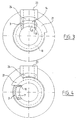
- Fig. 3
- shows a view according to arrow III in fig. 1 of the stop cams of the hose reel.
- Fig. 4
- shows a view corresponding with fig. 3 in another rotational position of the stop cams.
- Fig. 5A and 5B
- show the valve case in relation to the reel hub in two operating positions.
- Fig. 6
- is a view according to arrow VI in fig. 5 of the hose connecting means.
- Fig. 7
- is a view corresponding with fig. 6 of another embodiment.
- As shown in fig. 1, the reel comprises a drum 1 with side flanges 2 which is mounted on a
hub 3, which is arranged rotatably on ahollow shaft end 4. The latter is provided with asuspension slot 5 for fixing of the reel in a suspension plate arranged for instance on a wall, and with aconnection 7 which is connected to a water supply pipe 6.Hub 3 has aconnection 23 into which is fixedly screwed acoupling piece 8 which connects onto the one end of the hose 9 wound round the reel 1, 2. - As shown in fig. 1 and 2,
hub 3 is arranged rotatably round a valve case orvalve member 10. Arranged in the wall of the valve member is anopening 11 which forms a connection between the central cavity ofshaft end 4 and achamber 12 which is formed inshaft end 4 so that, when the still to be described valve member is located in the open position, water can flow from supply pipe 6 into theconnection 23 and therefrom into the hose 9. - Located inside the
hub 3 is arotatable valve member 10 which is formed by a case having thereon one ormore cams 21 and a chamber 20 forming an annular end face. In the wall ofvalve member 10 is arranged anopening 11 which, in the shown position ofvalve member 10, coincides withopenings 14, so that this shown position ofvalve member 10 is the open position. By rotatinghub 3 through about 30° theopenings 14 are placed out of coincidence withopenings 11 wherebyvalve member 10 is situated in the closed position. - The
valve member 10 is held relative toshaft end 4 by an elasticintermediate disc 15 which, under bias generated by thedisc 16, is pressed against the annular end face 20.Disc 16 cannot turn tangentially relative toshaft end 4 and thedisc 16 is biased by axial displacement by means of anut 17 which is arranged on a threadedportion 28 ofplug 18. Theplug 18 is screwed intoshaft end 4. Valvemember 10 is thus held in place by friction betweensurfaces 27 of theintermediate disc 15 and end face 20 ofvalve member 10 or friction between thesurfaces 29 ofintermediate disc disc 16. As thehub 3 can rotate freely roundvalve member 10, theopenings 14 ofhub 3 will coincide with the opening 11 ofvalve member 10 after unwinding of the hose through roughly 300°, so that themember 10 is opened. At that moment, as shown in fig. 3, thecam 24 ofhub 3 runs against acam 21 ofvalve member 10. Thevalve member 10 will hereby begin to co-rotate withhub 3round shaft end 4 andintermediate disc 15 will begin to slip againstvalve member 10 ordisc 16. - When the hose 9 is wound up, the rotation of
hub 3 is then in opposed direction, as shown in fig. 4, andhub 3 will in the first instance turn relative tovalve member 10 and, after roughly 30°, theopenings 14 ofhub 3 will no longer coincide with opening 11 ofvalve member 10, so that the latter is closed. After a time thecam 24 ofhub 3 runs against the other side ofcam 21 ofvalve member 10 and thevalve member 10 will begin to co-rotate withhub 3round shaft end 4 andintermediate disc 15 will begin to slip and the valve member remains closed. - As shown in fig. 5, the
valve member 10 is provided with aradial opening 11 which is sealed by aspecial seal groove 22 in which sealingring 19 is arranged. As shown in fig. 6, in order to hold sealingring 19 in place when it passes theopening 14, this latter is formed by a number ofholes 26 such that wall-like parts remain which hold the sealingring 19 pressed in, also in the case of strong water flows. Fig. 7 shows a preferred embodiment wherein slot-like holes 25 are applied. Here also the remaining wall parts enclose the sealingring 19.
Claims (6)
- Hose reel comprising a fixedly disposed shaft end (4), a reel hub (3) which is mounted rotatably round the shaft end (4) and which is provided with co-rotatable hose connecting means (23), wherein a water supply channel is defined which extends internally through the shaft end (4) and communicates with the hose connecting means through radial openings in the shaft end and the reel hub, and wherein the reel hub (3) is provided with a co-rotatable valve case (10) which lies directly round the shaft end (4) and which is rotatable through an angle relative to the reel hub (3) between a closed position, in which the radial opening therein is blocked, and an open position in which it is left open, characterized in that the valve case (10) is rotatably arranged on the shaft end (4) and the reel hub (3) is rotatably arranged on the valve case (10) and that a friction coupling is arranged, engaging the valve case and rotating this in the open position and vice versa at rotation of the reel hub, and in that the friction coupling engages the shaft end (4) and the valve case (10).
- Hose reel as claimed in claim 1, wherein the friction coupling comprises a disc (16) which is fixedly connected to an end face of the shaft end (4) and which lies, via a layer (15) of friction material, with a bias against an annular axial face of the valve case (10).
- Hose reel as claimed in claim 2, wherein the disc (16) is connected to the shaft end (4) by an axial bolt connection.
- Hose reel as claimed in claim 2 or 3, wherein the annular axial face of the valve case (10) bears a radial cam (24) which co-acts with a protrusion on the reel hub (3) to define the rotational positions of the valve case (10) corresponding with the open and closed position.
- Hose reel as claimed in any of the foregoing claims, wherein the valve case (10) comprises a radial opening (11) which in the open position coincides with the radial opening (14) in the reel hub (3), and in the mutually facing cylindrical surfaces of the valve case (10) and the reel hub (3) a groove is formed running round one of these openings, in which groove an O-ring (19) is arranged, and the other opening (14) is formed from a number of smaller openings (25, 26) with wall parts remaining therebetween.
- Hose reel as claimed in claim 5, wherein the smaller openings are elongate openings (25) in tangential direction.
Applications Claiming Priority (2)
| Application Number | Priority Date | Filing Date | Title |
|---|---|---|---|
| NL9400203A NL9400203A (en) | 1994-02-09 | 1994-02-09 | Hose reel. |
| NL9400203 | 1994-02-09 |
Publications (2)
| Publication Number | Publication Date |
|---|---|
| EP0667312A1 EP0667312A1 (en) | 1995-08-16 |
| EP0667312B1 true EP0667312B1 (en) | 1999-04-21 |
Family
ID=19863814
Family Applications (1)
| Application Number | Title | Priority Date | Filing Date |
|---|---|---|---|
| EP19950200318 Expired - Lifetime EP0667312B1 (en) | 1994-02-09 | 1995-02-09 | Hose reel |
Country Status (4)
| Country | Link |
|---|---|
| EP (1) | EP0667312B1 (en) |
| DE (1) | DE69509149T2 (en) |
| NL (1) | NL9400203A (en) |
| NO (1) | NO310698B1 (en) |
Cited By (2)
| Publication number | Priority date | Publication date | Assignee | Title |
|---|---|---|---|---|
| DE102010026118A1 (en) | 2010-07-05 | 2012-01-05 | Mkn Maschinenfabrik Kurt Neubauer Gmbh & Co. | Hose reeling system and cooking appliance equipped therewith |
| WO2012175564A1 (en) | 2011-06-23 | 2012-12-27 | Mkn Maschinenfabrik Kurt Neubauer Gmbh & Co. | Cooking device having a pan and method for cleaning the pan |
Families Citing this family (2)
| Publication number | Priority date | Publication date | Assignee | Title |
|---|---|---|---|---|
| EP0937674B1 (en) * | 1998-02-13 | 2002-03-27 | eloma GmbH Grossküchentechnik | Hose reeling device |
| FR2807419B1 (en) * | 2000-04-11 | 2003-02-07 | Pok Soc | FEEDER FOR SEMI-RIGID PIPE |
Family Cites Families (2)
| Publication number | Priority date | Publication date | Assignee | Title |
|---|---|---|---|---|
| US2578396A (en) * | 1945-10-12 | 1951-12-11 | Dole Valve Co | Valve and sealing structure therefor |
| NL8502159A (en) * | 1985-07-30 | 1987-02-16 | Pieter Van T Veer | Fire hose reel on hollow stub-shaft - has tube forming valve turning inside stub-shaft between stops |
-
1994
- 1994-02-09 NL NL9400203A patent/NL9400203A/en active Search and Examination
-
1995
- 1995-02-08 NO NO19950458A patent/NO310698B1/en not_active IP Right Cessation
- 1995-02-09 DE DE1995609149 patent/DE69509149T2/en not_active Expired - Lifetime
- 1995-02-09 EP EP19950200318 patent/EP0667312B1/en not_active Expired - Lifetime
Cited By (5)
| Publication number | Priority date | Publication date | Assignee | Title |
|---|---|---|---|---|
| DE102010026118A1 (en) | 2010-07-05 | 2012-01-05 | Mkn Maschinenfabrik Kurt Neubauer Gmbh & Co. | Hose reeling system and cooking appliance equipped therewith |
| EP2404858A2 (en) | 2010-07-05 | 2012-01-11 | MKN Maschinenfabrik Kurt Neubauer GmbH & Co. | Tube rewinding system and cooking device equipped with same |
| EP2404858A3 (en) * | 2010-07-05 | 2013-08-07 | MKN Maschinenfabrik Kurt Neubauer GmbH & Co. KG | Tube rewinding system and cooking device equipped with same |
| WO2012175564A1 (en) | 2011-06-23 | 2012-12-27 | Mkn Maschinenfabrik Kurt Neubauer Gmbh & Co. | Cooking device having a pan and method for cleaning the pan |
| DE102011105716A1 (en) | 2011-06-23 | 2012-12-27 | MKN Maschinenfabrik Kurt Neubauer GmbH & Co. KG | Cooking device with a crucible and method for cleaning the crucible |
Also Published As
| Publication number | Publication date |
|---|---|
| EP0667312A1 (en) | 1995-08-16 |
| NO950458L (en) | 1995-08-10 |
| NL9400203A (en) | 1995-09-01 |
| NO950458D0 (en) | 1995-02-08 |
| NO310698B1 (en) | 2001-08-13 |
| DE69509149D1 (en) | 1999-05-27 |
| DE69509149T2 (en) | 1999-08-12 |
Similar Documents
| Publication | Publication Date | Title |
|---|---|---|
| US5651280A (en) | Door lock | |
| US5697557A (en) | Shower head with switching mechanism | |
| US4678002A (en) | Faucet valve with adjustable stem tightener | |
| US6899171B2 (en) | Actuating device | |
| CA1319138C (en) | Disk valve | |
| US5076918A (en) | Quick change oil filter | |
| EP0667312B1 (en) | Hose reel | |
| US3057004A (en) | Hydraulic door closer | |
| US6202695B1 (en) | Water faucet control cartridge | |
| JPH10142251A (en) | Running water detector | |
| US4077426A (en) | Faucet valve and valve cartridge | |
| US3612094A (en) | Remote control hide-away hose | |
| US6189561B1 (en) | Valve cartridge for lift valve having the closing pressure on the sealing limited | |
| JP4176839B2 (en) | Valve cartridge for a lift valve with closing pressure based on limited sealing | |
| WO2000025028A1 (en) | Lockout device for valve actuators | |
| FR2432663A1 (en) | Flap valve with tangential axle - opens at rate set by torsion springs of which tension is adjusted by rotating head of lockable axle | |
| JP3631844B2 (en) | Flowing water detector | |
| SU1583693A1 (en) | Spherical valve control system | |
| US4311287A (en) | Web pay-out assembly | |
| GB2240538A (en) | Hose reel | |
| US4081172A (en) | Fluid valve | |
| AU625853B2 (en) | A disc valve | |
| IE900397A1 (en) | A hose-reel | |
| SU1236439A1 (en) | Differential pressure valve | |
| CN210069103U (en) | Anti-theft type valve hand wheel assembly |
Legal Events
| Date | Code | Title | Description |
|---|---|---|---|
| PUAI | Public reference made under article 153(3) epc to a published international application that has entered the european phase |
Free format text: ORIGINAL CODE: 0009012 |
|
| AK | Designated contracting states |
Kind code of ref document: A1 Designated state(s): BE DE FR NL |
|
| 17P | Request for examination filed |
Effective date: 19960214 |
|
| 17Q | First examination report despatched |
Effective date: 19970702 |
|
| GRAG | Despatch of communication of intention to grant |
Free format text: ORIGINAL CODE: EPIDOS AGRA |
|
| GRAG | Despatch of communication of intention to grant |
Free format text: ORIGINAL CODE: EPIDOS AGRA |
|
| GRAH | Despatch of communication of intention to grant a patent |
Free format text: ORIGINAL CODE: EPIDOS IGRA |
|
| GRAH | Despatch of communication of intention to grant a patent |
Free format text: ORIGINAL CODE: EPIDOS IGRA |
|
| GRAA | (expected) grant |
Free format text: ORIGINAL CODE: 0009210 |
|
| AK | Designated contracting states |
Kind code of ref document: B1 Designated state(s): BE DE FR NL |
|
| REF | Corresponds to: |
Ref document number: 69509149 Country of ref document: DE Date of ref document: 19990527 |
|
| ET | Fr: translation filed | ||
| PLBE | No opposition filed within time limit |
Free format text: ORIGINAL CODE: 0009261 |
|
| STAA | Information on the status of an ep patent application or granted ep patent |
Free format text: STATUS: NO OPPOSITION FILED WITHIN TIME LIMIT |
|
| 26N | No opposition filed | ||
| PGFP | Annual fee paid to national office [announced via postgrant information from national office to epo] |
Ref country code: NL Payment date: 20140228 Year of fee payment: 20 Ref country code: DE Payment date: 20140226 Year of fee payment: 20 |
|
| PGFP | Annual fee paid to national office [announced via postgrant information from national office to epo] |
Ref country code: BE Payment date: 20140226 Year of fee payment: 20 Ref country code: FR Payment date: 20140228 Year of fee payment: 20 |
|
| REG | Reference to a national code |
Ref country code: DE Ref legal event code: R071 Ref document number: 69509149 Country of ref document: DE |
|
| REG | Reference to a national code |
Ref country code: NL Ref legal event code: V4 Effective date: 20150209 |