EP0668084A1 - Method and arrangement in connection with a secretion receiver - Google Patents
Method and arrangement in connection with a secretion receiver Download PDFInfo
- Publication number
- EP0668084A1 EP0668084A1 EP94308175A EP94308175A EP0668084A1 EP 0668084 A1 EP0668084 A1 EP 0668084A1 EP 94308175 A EP94308175 A EP 94308175A EP 94308175 A EP94308175 A EP 94308175A EP 0668084 A1 EP0668084 A1 EP 0668084A1
- Authority
- EP
- European Patent Office
- Prior art keywords
- secretion
- solidifying
- receptacle
- container
- disinfecting agent
- Prior art date
- Legal status (The legal status is an assumption and is not a legal conclusion. Google has not performed a legal analysis and makes no representation as to the accuracy of the status listed.)
- Withdrawn
Links
- 230000028327 secretion Effects 0.000 title claims abstract description 91
- 238000000034 method Methods 0.000 title claims abstract description 7
- 239000000645 desinfectant Substances 0.000 claims abstract description 42
- 239000003795 chemical substances by application Substances 0.000 claims description 7
- 239000000843 powder Substances 0.000 claims description 3
- 239000007787 solid Substances 0.000 claims description 2
- 238000007711 solidification Methods 0.000 description 3
- 230000008023 solidification Effects 0.000 description 3
- 238000010420 art technique Methods 0.000 description 2
- 238000004140 cleaning Methods 0.000 description 2
- 230000000694 effects Effects 0.000 description 1
- 208000015181 infectious disease Diseases 0.000 description 1
- 230000036445 liquid secretion Effects 0.000 description 1
- 239000000463 material Substances 0.000 description 1
- 239000004033 plastic Substances 0.000 description 1
- 229920003023 plastic Polymers 0.000 description 1
- 238000004659 sterilization and disinfection Methods 0.000 description 1
- 239000000126 substance Substances 0.000 description 1
Images
Classifications
-
- A—HUMAN NECESSITIES
- A61—MEDICAL OR VETERINARY SCIENCE; HYGIENE
- A61M—DEVICES FOR INTRODUCING MEDIA INTO, OR ONTO, THE BODY; DEVICES FOR TRANSDUCING BODY MEDIA OR FOR TAKING MEDIA FROM THE BODY; DEVICES FOR PRODUCING OR ENDING SLEEP OR STUPOR
- A61M1/00—Suction or pumping devices for medical purposes; Devices for carrying-off, for treatment of, or for carrying-over, body-liquids; Drainage systems
- A61M1/88—Draining devices having means for processing the drained fluid, e.g. an absorber
- A61M1/882—Draining devices provided with means for releasing antimicrobial or gelation agents in the drained fluid
-
- A—HUMAN NECESSITIES
- A61—MEDICAL OR VETERINARY SCIENCE; HYGIENE
- A61M—DEVICES FOR INTRODUCING MEDIA INTO, OR ONTO, THE BODY; DEVICES FOR TRANSDUCING BODY MEDIA OR FOR TAKING MEDIA FROM THE BODY; DEVICES FOR PRODUCING OR ENDING SLEEP OR STUPOR
- A61M1/00—Suction or pumping devices for medical purposes; Devices for carrying-off, for treatment of, or for carrying-over, body-liquids; Drainage systems
- A61M1/60—Containers for suction drainage, adapted to be used with an external suction source
- A61M1/604—Bag or liner in a rigid container, with suction applied to both
Definitions
- the invention relates to a method in connection with a secretion receiver, wherein secretion is sucked by a vacuum created by a vacuum source into a secretion receptacle through a patient hose fitted in a first connection means of the secretion receptacle, and wherein solidifying and disinfecting agent is mixed with the secretion so as to solidify it.
- the invention also relates to an arrangement in connection with a secretion receiver, comprising a secretion receptacle, a first connection means for connecting a patient hose in flow connection with the secretion receptacle, and a second connection means for connecting a vacuum source to the secretion receptacle, the arrangement further comprising a container and containing solidifying and disinfecting agent for solidifying the secretion.
- the invention concerns a secretion receiver system for medical uses, for instance.
- the invention is intended for daily use e.g. in the hospital in connection with secretion receivers.
- the use of secretion receivers in the hospital has a number of risks, such as the risk of infection. Problems occur with such receivers particularly when the receiver leaks for some reason or when the receiver is broken so that the secretion escapes from the receiver. In certain cases, the required cleaning measures may be very difficult to carry out.
- the secretion receiver is also rather difficult to handle, as liquid secretion may spill and splash very easily. Spilled secretion may also cause problems if it enters the suction device.
- the main problem with the prior art technique has been the separate dispensing step of the solidifying and disinfecting agent, as risk situations may thus occur when the agent is handled and dispensed.
- Another problem is that the dispensing of the solidifying and disinfecting agent may sometimes be forgotten. If the agent is dispensed afterwards, the solidification of the secretion by the agent is retarded, in addition to which the tasks of the hospital personnel will be hampered and retarded particularly when the secretion receiver is to be changed during a medical procedure.
- the object of the invention is, in fact, to provide an arrangement, by means of which the disadvantages of the prior art can be eliminated. This is achieved by a method and an arrangement according to the invention.
- the method according to the invention is characterized in that the solidifying and disinfecting agent is positioned in the first connection means in such a way that it will be dispensed automatically under the influence of vacuum created by the vacuum source without any separate measures.
- the arrangement according to the invention in turn is characterized in that the container is positioned in the first connection means in such a way that a vacuum created by the vacuum source is arranged to cause the solidifying agent to be dispensed automatically without any separate measures.
- a major advantage of the invention is that it allows the level of hospital hygiene to be improved substantially over the prior art technique, as the solidification eliminates efficiently the problems caused by leaking and spreading of secretion.
- the invention prevents drops of secretion formed by splashing from entering into the vacuum source creating a suction effect in the secretion receiver.
- Another advantage of the invention is that it is simple, whereby it is advantageous to introduce and use.
- the first connection means is provided in a cover portion, the container being positioned in the cover portion.
- the cover portion may be arranged to close the secretion receptacle.
- the second connection means may be positioned in the cover portion.
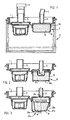
- Figure 1 is a general view of one embodiment of the arrangement according to the invention.
- the reference numeral 1 indicates a cover portion, and the reference numeral 2 an actual secretion receptacle.
- the secretion receptacle may comprise a disposable bag or a reusable receptacle or their combination.
- Figure 1 shows a solution, where a disposable bag is positioned inside a reusable receptacle.
- the cover portion 1 is arranged to be positioned tightly upon the actual secretion receptacle 2 so as to close it.
- the cover portion 1 is provided with a first connection means 3 which is arranged to connect a patient hose 4 into flow connection with the secretion receptacle 2.
- the cover portion is also provided with a second connection means 5 for connecting a vacuum source 6 to the secretion receptacle.
- a container 7 with solidifying and disinfecting agent 8 is provided in connection with the first connection means 3 in the cover portion 1.
- the solidifying and disinfecting agent may be any suitable agent commercially available.
- One example would be a substance sold under the name Sanisorb and manufactured by Premium Plastics Inc., USA.
- the container 7 may be installed in position either at the factory stage or afterwards.
- vacuum created by the vacuum source 6 is arranged to provide automatically, without any separate measures, a contact between the solidifying and disinfecting agent 8 and the secretion flowing through the patient hose 3.
- the solidifying and disinfecting agent is arranged in connection with the secretion receptacle 2 in such a way that a vacuum connected to the secretion receptacle 2 from the vacuum source 6 detaches the container 7, thus allowing the solidifying and disinfecting agent 8 to fall into the secretion receptacle 2, and the vacuum is admitted into the patient hose 4, by means of which secretion is sucked into the secretion receptacle 2.
- an appropriate amount of the solidifying and disinfecting agent will always be positioned in the secretion receptacle when secretion flows into it.
- the container 7 is formed by a cup-like bottom portion 9 attached to a retainer 10 positioned inside the cover portion 1.
- the cup-like bottom portion may also be made of a number of parts.
- the term inside means that surface of the cover portion 1 which will be positioned within the secretion receptacle when the cover portion is mounted upon the secretion receptacle 2.
- the idea is that the bottom portion 9 is detached under the influence of vacuum and falls into the secretion receptacle 2 so that the vacuum is able to act on the patient hose and thus suck secretion from the patient into the secretion receptacle, where it comes into contact with the solidifying and disinfecting agent that has dropped into it.
- An appropriate amount of the solidifying and disinfecting agent will be dispensed in advance into the receptacle portion; container portions may, for instance, be supplied with solidifying and disinfecting agent provided within them.
- the solidifying and disinfecting agent 8 will be mixed with the secretion fully automatically when the vacuum source 6 is switched on. In this embodiment, all of the solidifying and disinfecting agent 8 is arranged to be mixed with the secretion at the same time.
- the solidifying and disinfecting agent 8 may be e.g. in powder form.
- Figure 2 shows a second embodiment of the arrangement according to the invention.
- the structure is similar to the embodiment shown in Figure 1.
- This embodiment corresponds essentially to that shown in Figure 1, the only difference being the structure of a container 17.
- the container 17 is formed by a bottom portion 19a and a wall portion 19b.
- the wall portion 19b is attached to a retainer 20 provided in the cover portion 1, and the bottom portion correspondingly to the lower edge of the wall portion.
- the bottom portion 19a is detached by the influence of vacuum, so that the solidifying and disinfecting agent 8 will make contact with secretion flowing through a patient hose and flow openings formed in the wall portion, whereby the solidifying and disinfecting agent solidifies and disinfects the secretion. It is also possible that the wall portion 19b is detached and then falls into the secretion receptacle. The operation is similar to that described with reference to Figure 1.
- Figure 3 shows two versions of a third embodiment of the invention.
- a vacuum created in the secretion receptacle detaches a closing part 29c fitted in the first connection means 3, whereby secretion from the patient is able to flow into the receptacle portion 27a or 27b.
- the wall portion 29a or 29b of the container remains attached to the cover portion.
- the idea is that the apparatus in a way dispenses solidifying and disinfecting agent 8 into the secretion while suction is effected. The flow takes place through openings formed in the wall portions 29a and 29b.
- the solidifying and disinfecting agent 8 can be in the container e.g. in powder form.
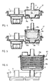
- Figure 4 shows a fourth embodiment of the arrangement according to the invention.
- the container 37 is positioned outside the cover portion 1.
- the container 37 comprises a cover 39a, a wall portion 39b, and closing parts 39c and 39d.
- the idea is that the closing parts 39c and 39d open under the influence of vacuum, whereby the solidifying and disinfecting agent 8 falls into the secretion receptacle.
- the operation is similar to that described with reference to the example of Figure 1.
- Figure 5 shows a fifth embodiment of the arrangement according to the invention.
- the container 47 is, in principle, similar to that of the example shown in Figure 4, i.e. it comprises a cover 49a, wall portions 49b, and closing parts 49c and 49d. The closing parts are opened as described with reference to Figure 4.
- a characteristic feature of this embodiment is that the solidifying and disinfecting agent is packed in a separate cup or the like 8a, which is fitted in the container 47.
- the solidifying and disinfecting agent is in solid form, as it may be difficult in certain conditions to hold a powder-like material in the cup 8a.
- Figure 6 shows a sixth embodiment of the arrangement according to the invention.
- the container 57 comprises a cover 59a, a wall portion 57b, and a screen portion 57c.
- the solidifying and disinfecting agent 8 is in the form of a ring-shaped tablet arranged on the bottom of the screen portion 59c. Secretion removed from the patient under the influence of vacuum comes into contact with the solidifying and disinfecting agent, which is dissolved in the secretion and entrained with it. In this embodiment, secretion flows through the container 57, so that the solidifying and disinfecting agent is gradually dissolved in the flow of secretion.
- the operation corresponds to the operating principles disclosed in connection with the embodiments disclosed above.
- This embodiment advantageously allows solidifying and disinfecting agent to be used only when it is needed, as the container can be attached rapidly to the first connection means, if required.
- the arrangement shown in Figure 6 is suitable for existing secretion receiving bags.
- the version shown in Figure 6 can be advantageously supplied to hospitals as a separate part.
Landscapes
- Health & Medical Sciences (AREA)
- Heart & Thoracic Surgery (AREA)
- Vascular Medicine (AREA)
- Engineering & Computer Science (AREA)
- Anesthesiology (AREA)
- Biomedical Technology (AREA)
- Hematology (AREA)
- Life Sciences & Earth Sciences (AREA)
- Animal Behavior & Ethology (AREA)
- General Health & Medical Sciences (AREA)
- Public Health (AREA)
- Veterinary Medicine (AREA)
- External Artificial Organs (AREA)
Abstract
Description
- The invention relates to a method in connection with a secretion receiver, wherein secretion is sucked by a vacuum created by a vacuum source into a secretion receptacle through a patient hose fitted in a first connection means of the secretion receptacle, and wherein solidifying and disinfecting agent is mixed with the secretion so as to solidify it. The invention also relates to an arrangement in connection with a secretion receiver, comprising a secretion receptacle, a first connection means for connecting a patient hose in flow connection with the secretion receptacle, and a second connection means for connecting a vacuum source to the secretion receptacle, the arrangement further comprising a container and containing solidifying and disinfecting agent for solidifying the secretion.
- The invention concerns a secretion receiver system for medical uses, for instance. The invention is intended for daily use e.g. in the hospital in connection with secretion receivers.
- The use of secretion receivers in the hospital has a number of risks, such as the risk of infection. Problems occur with such receivers particularly when the receiver leaks for some reason or when the receiver is broken so that the secretion escapes from the receiver. In certain cases, the required cleaning measures may be very difficult to carry out. The secretion receiver is also rather difficult to handle, as liquid secretion may spill and splash very easily. Spilled secretion may also cause problems if it enters the suction device.
- To avoid the over-described problems, systems have been developed recently which use a special solidifying and disinfecting agent which solidifies and disinfects the secretion, so that the secretion will not splash and, in cases of accident, cleaning is considerably easier to carry out than previously. The solidifying and disinfecting agent is dispensed in a separate step with a suitable dispenser into the secretion.
- The main problem with the prior art technique has been the separate dispensing step of the solidifying and disinfecting agent, as risk situations may thus occur when the agent is handled and dispensed. Another problem is that the dispensing of the solidifying and disinfecting agent may sometimes be forgotten. If the agent is dispensed afterwards, the solidification of the secretion by the agent is retarded, in addition to which the tasks of the hospital personnel will be hampered and retarded particularly when the secretion receiver is to be changed during a medical procedure.
- The object of the invention is, in fact, to provide an arrangement, by means of which the disadvantages of the prior art can be eliminated. This is achieved by a method and an arrangement according to the invention. The method according to the invention is characterized in that the solidifying and disinfecting agent is positioned in the first connection means in such a way that it will be dispensed automatically under the influence of vacuum created by the vacuum source without any separate measures. The arrangement according to the invention in turn is characterized in that the container is positioned in the first connection means in such a way that a vacuum created by the vacuum source is arranged to cause the solidifying agent to be dispensed automatically without any separate measures.
- A major advantage of the invention is that it allows the level of hospital hygiene to be improved substantially over the prior art technique, as the solidification eliminates efficiently the problems caused by leaking and spreading of secretion. In addition, the invention prevents drops of secretion formed by splashing from entering into the vacuum source creating a suction effect in the secretion receiver. Another advantage of the invention is that it is simple, whereby it is advantageous to introduce and use. Preferably, the first connection means is provided in a cover portion, the container being positioned in the cover portion. The cover portion may be arranged to close the secretion receptacle. The second connection means may be positioned in the cover portion.
- In the following the invention will be described more fully by means of the embodiments shown in the attached drawings, whereby
- Figure 1 is a general side view of a first embodiment of the arrangement according to the invention;
- Figure 2 is a general side view of a second embodiment of the arrangement according to the invention;
- Figure 3 is a general side view of a third embodiment of the arrangement according to the invention;
- Figure 4 is a general side view of a fourth embodiment of the arrangement according to the invention;
- Figure 5 is a general side view of a fifth embodiment of the arrangement according to the invention;
- Figure 6 is a general side view of a sixth embodiment of the arrangement according to the invention.
- Figure 1 is a general view of one embodiment of the arrangement according to the invention. The
reference numeral 1 indicates a cover portion, and thereference numeral 2 an actual secretion receptacle. The secretion receptacle may comprise a disposable bag or a reusable receptacle or their combination. Figure 1 shows a solution, where a disposable bag is positioned inside a reusable receptacle. Thecover portion 1 is arranged to be positioned tightly upon theactual secretion receptacle 2 so as to close it. Thecover portion 1 is provided with a first connection means 3 which is arranged to connect a patient hose 4 into flow connection with thesecretion receptacle 2. The cover portion is also provided with a second connection means 5 for connecting a vacuum source 6 to the secretion receptacle. - The structure and operation of the secretion receptacle, hoses and vacuum source are fully obvious to one skilled in the art, so they will not be described more fully herein. It is only to be noted in this connection that the patient hose 4 is connected to the patient, and a vacuum created by the vacuum source 6 in the
secretion receptacle 2 sucks secretion from the patient through the patient hose 4 into thesecretion receptacle 2. - According to an essential basic idea of the invention, a
container 7 with solidifying and disinfectingagent 8 is provided in connection with the first connection means 3 in thecover portion 1. The solidifying and disinfecting agent may be any suitable agent commercially available. One example would be a substance sold under the name Sanisorb and manufactured by Premium Plastics Inc., USA. Thecontainer 7 may be installed in position either at the factory stage or afterwards. To solidify the secretion, vacuum created by the vacuum source 6 is arranged to provide automatically, without any separate measures, a contact between the solidifying and disinfectingagent 8 and the secretion flowing through thepatient hose 3. The idea of the embodiment shown in Figure 1 is that the solidifying and disinfecting agent is arranged in connection with thesecretion receptacle 2 in such a way that a vacuum connected to thesecretion receptacle 2 from the vacuum source 6 detaches thecontainer 7, thus allowing the solidifying and disinfectingagent 8 to fall into thesecretion receptacle 2, and the vacuum is admitted into the patient hose 4, by means of which secretion is sucked into thesecretion receptacle 2. In this embodiment, an appropriate amount of the solidifying and disinfecting agent will always be positioned in the secretion receptacle when secretion flows into it. - In the embodiment shown in Figure 1, the
container 7 is formed by a cup-like bottom portion 9 attached to aretainer 10 positioned inside thecover portion 1. The cup-like bottom portion may also be made of a number of parts. As used herein, the term inside means that surface of thecover portion 1 which will be positioned within the secretion receptacle when the cover portion is mounted upon thesecretion receptacle 2. The idea is that the bottom portion 9 is detached under the influence of vacuum and falls into thesecretion receptacle 2 so that the vacuum is able to act on the patient hose and thus suck secretion from the patient into the secretion receptacle, where it comes into contact with the solidifying and disinfecting agent that has dropped into it. An appropriate amount of the solidifying and disinfecting agent will be dispensed in advance into the receptacle portion; container portions may, for instance, be supplied with solidifying and disinfecting agent provided within them. - It is to be noted that the solidifying and disinfecting
agent 8 will be mixed with the secretion fully automatically when the vacuum source 6 is switched on. In this embodiment, all of the solidifying and disinfectingagent 8 is arranged to be mixed with the secretion at the same time. The solidifying and disinfectingagent 8 may be e.g. in powder form. - Figure 2 shows a second embodiment of the arrangement according to the invention. In Figure 2, only the
cover portion 1 is shown for the sake of clarity. In other respects, the structure is similar to the embodiment shown in Figure 1. This embodiment corresponds essentially to that shown in Figure 1, the only difference being the structure of a container 17. In this embodiment, the container 17 is formed by abottom portion 19a and a wall portion 19b. The wall portion 19b is attached to a retainer 20 provided in thecover portion 1, and the bottom portion correspondingly to the lower edge of the wall portion. The idea of this embodiment is that thebottom portion 19a is detached by the influence of vacuum, so that the solidifying and disinfectingagent 8 will make contact with secretion flowing through a patient hose and flow openings formed in the wall portion, whereby the solidifying and disinfecting agent solidifies and disinfects the secretion. It is also possible that the wall portion 19b is detached and then falls into the secretion receptacle. The operation is similar to that described with reference to Figure 1. - Figure 3 shows two versions of a third embodiment of the invention. In this embodiment, a vacuum created in the secretion receptacle detaches a
closing part 29c fitted in the first connection means 3, whereby secretion from the patient is able to flow into thereceptacle portion wall portion agent 8 into the secretion while suction is effected. The flow takes place through openings formed in thewall portions agent 8 can be in the container e.g. in powder form. - Figure 4 shows a fourth embodiment of the arrangement according to the invention. In this embodiment the
container 37 is positioned outside thecover portion 1. Thecontainer 37 comprises acover 39a, awall portion 39b, and closingparts closing parts agent 8 falls into the secretion receptacle. In principle, the operation is similar to that described with reference to the example of Figure 1. - Figure 5 shows a fifth embodiment of the arrangement according to the invention. In this embodiment, the
container 47 is, in principle, similar to that of the example shown in Figure 4, i.e. it comprises acover 49a,wall portions 49b, and closingparts agent 8 is not released at the same time, but it is dissolved or entrained in secretion flowing through thecontainer 47 into the secretion receptacle, where the solidification and disinfection take place as described above. A characteristic feature of this embodiment is that the solidifying and disinfecting agent is packed in a separate cup or the like 8a, which is fitted in thecontainer 47. In this embodiment, it is preferable that the solidifying and disinfecting agent is in solid form, as it may be difficult in certain conditions to hold a powder-like material in thecup 8a. - Figure 6 shows a sixth embodiment of the arrangement according to the invention. In this embodiment, the
container 57 comprises acover 59a, a wall portion 57b, and a screen portion 57c. In this embodiment, the solidifying and disinfectingagent 8 is in the form of a ring-shaped tablet arranged on the bottom of thescreen portion 59c. Secretion removed from the patient under the influence of vacuum comes into contact with the solidifying and disinfecting agent, which is dissolved in the secretion and entrained with it. In this embodiment, secretion flows through thecontainer 57, so that the solidifying and disinfecting agent is gradually dissolved in the flow of secretion. In other respects, the operation corresponds to the operating principles disclosed in connection with the embodiments disclosed above. This embodiment advantageously allows solidifying and disinfecting agent to be used only when it is needed, as the container can be attached rapidly to the first connection means, if required. The arrangement shown in Figure 6 is suitable for existing secretion receiving bags. The version shown in Figure 6 can be advantageously supplied to hospitals as a separate part. - The embodiments described above are by no means intended to restrict the invention, but the invention can be modified at will within the scope of the claims. Accordingly, it is obvious that the arrangement according to the invention or its details need not necessarily be exactly similar to those shown in the figures, but other solutions are possible as well.
Claims (11)
Applications Claiming Priority (2)
| Application Number | Priority Date | Filing Date | Title |
|---|---|---|---|
| FI940721A FI101127B (en) | 1994-02-16 | 1994-02-16 | Method and apparatus of a secretory collection vessel |
| FI940721 | 1994-02-16 |
Publications (1)
| Publication Number | Publication Date |
|---|---|
| EP0668084A1 true EP0668084A1 (en) | 1995-08-23 |
Family
ID=8540126
Family Applications (1)
| Application Number | Title | Priority Date | Filing Date |
|---|---|---|---|
| EP94308175A Withdrawn EP0668084A1 (en) | 1994-02-16 | 1994-11-07 | Method and arrangement in connection with a secretion receiver |
Country Status (2)
| Country | Link |
|---|---|
| EP (1) | EP0668084A1 (en) |
| FI (1) | FI101127B (en) |
Cited By (6)
| Publication number | Priority date | Publication date | Assignee | Title |
|---|---|---|---|---|
| WO2000047246A1 (en) * | 1999-02-13 | 2000-08-17 | Rainer Ballnath | Dosing device in a medical vacuum container |
| US8418868B2 (en) | 2008-07-15 | 2013-04-16 | Medela Holding Ag | Fluid-collecting container |
| CN104127921A (en) * | 2014-07-22 | 2014-11-05 | 吉林大学 | Sputum aspirator capable of being operated by patient |
| WO2018007683A1 (en) * | 2016-07-06 | 2018-01-11 | Serres Oy | An apparatus for collecting fluid during a medical or surgical operation and a method for solidifying fluid in a collection container |
| CN114401754A (en) * | 2019-09-20 | 2022-04-26 | 大研医器株式会社 | Waste liquid storage container, waste liquid container provided with same, and waste liquid suction system |
| WO2023274534A1 (en) * | 2021-07-01 | 2023-01-05 | Serres Oy | A collection container |
Citations (3)
| Publication number | Priority date | Publication date | Assignee | Title |
|---|---|---|---|---|
| EP0254607A2 (en) * | 1986-06-24 | 1988-01-27 | FUTUR-QUOTIDIEN S.A. Société dite : | Apparatus for the autotransfusion of blood |
| US4855064A (en) * | 1988-01-13 | 1989-08-08 | Viratec, Inc. | Apparatus and method for decontaminating virus-infected body fluids |
| EP0390095A1 (en) * | 1989-03-30 | 1990-10-03 | Abbott Laboratories | Suction drainage infection control system |
-
1994
- 1994-02-16 FI FI940721A patent/FI101127B/en active
- 1994-11-07 EP EP94308175A patent/EP0668084A1/en not_active Withdrawn
Patent Citations (3)
| Publication number | Priority date | Publication date | Assignee | Title |
|---|---|---|---|---|
| EP0254607A2 (en) * | 1986-06-24 | 1988-01-27 | FUTUR-QUOTIDIEN S.A. Société dite : | Apparatus for the autotransfusion of blood |
| US4855064A (en) * | 1988-01-13 | 1989-08-08 | Viratec, Inc. | Apparatus and method for decontaminating virus-infected body fluids |
| EP0390095A1 (en) * | 1989-03-30 | 1990-10-03 | Abbott Laboratories | Suction drainage infection control system |
Cited By (11)
| Publication number | Priority date | Publication date | Assignee | Title |
|---|---|---|---|---|
| WO2000047246A1 (en) * | 1999-02-13 | 2000-08-17 | Rainer Ballnath | Dosing device in a medical vacuum container |
| US8418868B2 (en) | 2008-07-15 | 2013-04-16 | Medela Holding Ag | Fluid-collecting container |
| CN104127921A (en) * | 2014-07-22 | 2014-11-05 | 吉林大学 | Sputum aspirator capable of being operated by patient |
| WO2018007683A1 (en) * | 2016-07-06 | 2018-01-11 | Serres Oy | An apparatus for collecting fluid during a medical or surgical operation and a method for solidifying fluid in a collection container |
| WO2018007687A1 (en) * | 2016-07-06 | 2018-01-11 | Serres Oy | A collection liner for a medical or a surgical operation |
| JP2019520173A (en) * | 2016-07-06 | 2019-07-18 | セーレス オーワイ | Device for collecting fluid during medical or surgical operation and method for coagulating fluid in a collection container |
| US11129928B2 (en) | 2016-07-06 | 2021-09-28 | Serres Oy | Assembly for collecting fluid during a medical or a surgical operation |
| US11285255B2 (en) | 2016-07-06 | 2022-03-29 | Serres Oy | Collection liner for a medical or a surgical operation |
| CN114401754A (en) * | 2019-09-20 | 2022-04-26 | 大研医器株式会社 | Waste liquid storage container, waste liquid container provided with same, and waste liquid suction system |
| WO2023274534A1 (en) * | 2021-07-01 | 2023-01-05 | Serres Oy | A collection container |
| JP2024523953A (en) * | 2021-07-01 | 2024-07-04 | セレス オサケ ユキチュア | Collection container |
Also Published As
| Publication number | Publication date |
|---|---|
| FI940721A0 (en) | 1994-02-16 |
| FI940721L (en) | 1995-08-17 |
| FI101127B (en) | 1998-04-30 |
Similar Documents
| Publication | Publication Date | Title |
|---|---|---|
| US7115115B2 (en) | Medical suction system | |
| JP7386926B2 (en) | fluid collection system | |
| US3832738A (en) | Mid-stream urine collector | |
| US3719197A (en) | Aseptic suction drainage system and valve therefor | |
| US4734198A (en) | Dialysis solution mixing system | |
| US4957492A (en) | Apparatus for collecting and handling tissue during uterine evacuation procedure | |
| US7481243B2 (en) | Method and apparatus for the disposal of waste fluids | |
| EP1225930B1 (en) | Suction bag assembly | |
| CA2166261A1 (en) | Suction canister apparatus and method | |
| GB2292606A (en) | Body fluid testing kit | |
| JP2003531688A (en) | Method and apparatus for collecting and transferring liquids, especially blood | |
| EP0668084A1 (en) | Method and arrangement in connection with a secretion receiver | |
| US7780640B1 (en) | Spill proof catheter collector bag | |
| AU733213B2 (en) | Compact liquid dosing apparatus with a reservoir | |
| US7585292B2 (en) | Medical suction apparatus and draining of same | |
| US6105639A (en) | Closed delivery system | |
| JP4532638B2 (en) | Float for liquid waste treatment equipment | |
| WO1984002078A1 (en) | Device for sucking and removing medical liquids | |
| WO2001083004A1 (en) | Method and apparatus for dosage of an additive while collecting a liquid | |
| CA2182280A1 (en) | Closure delivery system | |
| CN112472894B (en) | System and method for leak-free connection of a concentrate container to a blood processing device | |
| JPH0380498B2 (en) | ||
| EP0996331B1 (en) | Device for preparing cleaning liquid for a milking device, and a cleaning agent, for example for use in the device | |
| US20100059139A1 (en) | Syringe filling apparatus | |
| KR20220062073A (en) | Systems and methods for leak-free connecting concentrate containers to blood treatment devices |
Legal Events
| Date | Code | Title | Description |
|---|---|---|---|
| PUAI | Public reference made under article 153(3) epc to a published international application that has entered the european phase |
Free format text: ORIGINAL CODE: 0009012 |
|
| AK | Designated contracting states |
Kind code of ref document: A1 Designated state(s): AT BE CH DE DK ES FR GB GR IE IT LI LU MC NL PT SE |
|
| 17P | Request for examination filed |
Effective date: 19950905 |
|
| 17Q | First examination report despatched |
Effective date: 19970227 |
|
| RTI1 | Title (correction) |
Free format text: ARRANGEMENT IN CONNECTION WITH A SECRETION RECEIVER |
|
| GRAG | Despatch of communication of intention to grant |
Free format text: ORIGINAL CODE: EPIDOS AGRA |
|
| GRAG | Despatch of communication of intention to grant |
Free format text: ORIGINAL CODE: EPIDOS AGRA |
|
| GRAH | Despatch of communication of intention to grant a patent |
Free format text: ORIGINAL CODE: EPIDOS IGRA |
|
| STAA | Information on the status of an ep patent application or granted ep patent |
Free format text: STATUS: THE APPLICATION IS DEEMED TO BE WITHDRAWN |
|
| 18D | Application deemed to be withdrawn |
Effective date: 20010308 |