EP0668209B1 - Cadre de bicyclette à géométric variable - Google Patents
Cadre de bicyclette à géométric variable Download PDFInfo
- Publication number
- EP0668209B1 EP0668209B1 EP19950200365 EP95200365A EP0668209B1 EP 0668209 B1 EP0668209 B1 EP 0668209B1 EP 19950200365 EP19950200365 EP 19950200365 EP 95200365 A EP95200365 A EP 95200365A EP 0668209 B1 EP0668209 B1 EP 0668209B1
- Authority
- EP
- European Patent Office
- Prior art keywords
- crankshaft
- frame
- bicycle
- saddle
- suspension element
- Prior art date
- Legal status (The legal status is an assumption and is not a legal conclusion. Google has not performed a legal analysis and makes no representation as to the accuracy of the status listed.)
- Expired - Lifetime
Links
Images

Classifications
-
- B—PERFORMING OPERATIONS; TRANSPORTING
- B62—LAND VEHICLES FOR TRAVELLING OTHERWISE THAN ON RAILS
- B62K—CYCLES; CYCLE FRAMES; CYCLE STEERING DEVICES; RIDER-OPERATED TERMINAL CONTROLS SPECIALLY ADAPTED FOR CYCLES; CYCLE AXLE SUSPENSIONS; CYCLE SIDECARS, FORECARS, OR THE LIKE
- B62K3/00—Bicycles
- B62K3/02—Frames
- B62K3/06—Frames of open type
-
- B—PERFORMING OPERATIONS; TRANSPORTING
- B62—LAND VEHICLES FOR TRAVELLING OTHERWISE THAN ON RAILS
- B62K—CYCLES; CYCLE FRAMES; CYCLE STEERING DEVICES; RIDER-OPERATED TERMINAL CONTROLS SPECIALLY ADAPTED FOR CYCLES; CYCLE AXLE SUSPENSIONS; CYCLE SIDECARS, FORECARS, OR THE LIKE
- B62K19/00—Cycle frames
- B62K19/30—Frame parts shaped to receive other cycle parts or accessories
- B62K19/36—Frame parts shaped to receive other cycle parts or accessories for attaching saddle pillars, e.g. adjustable during ride
-
- B—PERFORMING OPERATIONS; TRANSPORTING
- B62—LAND VEHICLES FOR TRAVELLING OTHERWISE THAN ON RAILS
- B62K—CYCLES; CYCLE FRAMES; CYCLE STEERING DEVICES; RIDER-OPERATED TERMINAL CONTROLS SPECIALLY ADAPTED FOR CYCLES; CYCLE AXLE SUSPENSIONS; CYCLE SIDECARS, FORECARS, OR THE LIKE
- B62K25/00—Axle suspensions
- B62K25/04—Axle suspensions for mounting axles resiliently on cycle frame or fork
- B62K25/28—Axle suspensions for mounting axles resiliently on cycle frame or fork with pivoted chain-stay
Definitions
- the invention relates to a bicycle according to the introductory portion of claim 1.
- the suspension element is adjustable by varying the axial force exerted by a secondary helical spring onto a shock absorber to control the friction generated by the shock absorber. Adjusting this secondary spring entails the side-effect that the force exerted by the secondary spring onto the main spring suspending the first frame part relative to the second frame part, by which force the main spring is compressed, is slightly changed.
- Such bicycles and other bicycles known from practice are offered in a large variety of designs which especially differ from each other in the extent to which they are suitable for realizing high average speeds and in the amount to which they offer comfort in use.
- racing and sports bicycles which enable high average speeds to be attained and on the other there are citybikes on which the rider is seated in a more comfortable but yet unnaturally bent position and which provides more comfortable though not highly comfortable riding properties.
- the object of the invention is to provide a bicycle which offers improved riding and seat comfort over the citybike and which is at least substantially equally suitable for rapidly covering longer distances.
- the inclination of the steering rod of the front wheel suspension (the steering head angle) and the angle of a line, approximately parallel thereto, passing through the bicycle saddle and the crankshaft can be varied between a level position, wherein the bicycle offers particularly comfortable riding properties and enables an upright sitting position which is highly comfortable, especially in urban traffic, and a steep position, wherein the riding properties and sitting position are less comfortable but wherein the rider is better capable of utilizing his body weight for applying force to the pedals.
- the rider can thus adjust the bicycle to a comfortable position for the purpose of riding in urban traffic and over short distances, which entails frequent mounting and dismounting, and change the setting to an active position as soon as longer distances are to be cycled at more constant speeds.
- the different settings of the suspension element define corresponding fixed relative distances between the parts of the frame.
- the suspension element it is also possible for the suspension element to simultaneously constitute a spring element.
- a given setting of the suspension element is not associated with a fixed position but with a particular load/position curve. Accordingly, upon a change of the setting of the suspension element, not a fixed relative position of the parts of the frame will be modified, but the relative operative equilibrium position of the parts of the frame such as it arises at a given load will be adjusted.
- the parts of the frame will each time show deviations from a particular operative equilibrium position and return to that operative equilibrium position.
- the invention can further be embodied in a bicycle frame according to claim 15, which is especially adapted for use in a bicycle according to the invention.
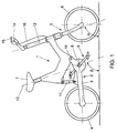
- the bicycle according to the exemplary embodiment of the invention as shown in Fig. 1 comprises a frame 1 including a rear wheel suspension 2 comprising a rearwardly projecting arm 3 adjacent the end of which a rear wheel 4 is suspended.
- the bicycle further comprises a steerable front wheel suspension 5 in which a front wheel 6 is suspended, a saddle 7 and a pedal set 9 rotatable about a crankshaft 8.
- the frame 1 comprises two parts capable of relative pivotal movement about a pivot 10 parallel to the crankshaft 8.
- a first part carries the front wheel suspension 5 and the saddle 7 and a second part carries at least the rearwardly projecting arm 3.
- Mounted between the first and the second part is a springy suspension element 11 for the purpose of maintaining the first and the second part in a relative, load-dependent operative equilibrium position with respect to each other.
- the suspension element 11 is adjustable for the purpose of adjusting that operative equilibrium position.
- the inclination of the steering rod 12 of the front wheel suspension 5 (the steering head angle) and the angle of a line 13, approximately parallel thereto, passing through the saddle 7 and the crankshaft 8 (the seat tube angle) can be varied between a relatively acute angle, preferably about 61-63°, in which the bicycle offers particularly comfortable riding properties and enables an upright sitting position which is highly comfortable especially in urban traffic, and a relatively obtuse angle, preferably 70-72°, in which riding properties and sitting position are less comfortable but in which the rider is better capable of employing his body weight for applying force to the pedals.
- the rider can adjust the bicycle to a comfortable position for the purpose of riding in urban traffic and over short distances, which entails frequent mounting and dismounting, and change the setting to an active position as soon as longer distances are to be cycled at more constant speeds.
- the adjustable suspension element 11 of substantially rigid construction.
- the different settings of the suspension element 11 define corresponding, substantially fixed relative positions of the parts of the frame 1.
- the suspension element 11 at the same time constitutes a spring element permitting load-dependent deviations from an operative equilibrium position in each setting.
- a given setting of the suspension element 1 is not associated with a fixed position of the parts of the frame but with a particular load/position curve. Accordingly, a change of the setting of the suspension element 11 does not involve a modification of a fixed relative position of the parts of the frame 1 but an adjustment of the relative operative equilibrium position of the parts of the frame 1 arising at a given load.
- the parts of the frame 1 will continually show deviations from the operative equilibrium position and return to that operative equilibrium position again.
- the geometry of the parts of the frame 1 as well as the adjustment possibilities of the suspension element are preferably chosen such that the steering head angle ⁇ and the seat tube angle ⁇ , which are mostly approximately equal, are adjustable between a comfortable setting and an active setting, whereby the angles ⁇ and ⁇ , if the bicycle is in the service position, are less than 69° when the suspension element 11 is in the comfortable setting and more than 70° (i.e. at least 1° more) when the suspension element 11 is in the active setting.
- a highly improved riding and practical comfort can be achieved if the steering head angle ⁇ and the seat tube angle ⁇ are less than 65° (i.e. at least 5° less than in the active position) if the suspension element 11 has been adjusted to the comfortable setting.
- crankshaft 8 is bearing-mounted in the rearwardly projecting arm 3, and thus in the second part of the frame 1, and located rearwardly of the pivot 10. This provides the advantage that upon adjustment of the suspension element 11 the distance from the crankshaft 8 to the ground varies relatively little. A raised position of the crankshaft 8 makes it more difficult to mount and dismount and a lowered position of the crankshaft 8 increases the danger of the pedals touching the road surface when negotiating bends.
- crankshaft 8 is located lower than the pivot 10 also contributes to the limitation of variation in the distance between the crankshaft 8 and the ground when varying the length of the suspension element 11.
- the centre-to-centre distance between the crankshaft 8 and the pivot 10 is 75-125 mm.
- the variation in the distance between the crankshaft 8 and the road surface is limited and on the other the variation in the distance between the crankshaft 8 and the saddle 7 is limited.
- This distance is slightly smaller in the comfortable setting than in the active setting is not a drawback because during riding in the comfortable setting, driving efficiency is of secondary importance.
- the suspension element 11 between the first part and the second part of the frame 1 comprises a length-adjustable gas spring. Similar gas springs are for instance used in office chairs and provide the advantage that adjustability, springing provisions and damping are united in a compact unit.
- the bicycle shown comprises a handlebar 14, which, for the purpose of increasing operating convenience, mounts an operating means 15 for remote adjustment of the length of the gas spring 11.
- the geometry of the frame 1 as a whole can thus be adjusted during cycling and without the necessity of dismounting.
- the operating means 15 is connected with the gas spring 11 through a Bowden cable 16.
- the gas spring communicates with a hydraulic pump and an electric motor for driving the pump, which electric motor is remotely operable by means of an operating means.
- the drive of the bicycle shown is constructed as a cardan drive accommodated in the rearwardly projecting arm 3. Because the complete drive is suspended from the rearwardly projecting arm 3 which forms a rigid whole, it is not necessary to make the transmission of flexible design for compensating distance variations due to compression and extension. Further, the drive is well protected and can be supplied as a complete subassembly and be easily mounted.
- Fig. 2 shows a bicycle according to the invention with the saddle 7 so fixed relative to a portion 17 of the suspension element 11 which is adjustable with respect to the first part of the frame 1, that upon adjustment of the suspension element 11 a set position of the saddle 7 with respect to that adjustable portion of the suspension element 11 is maintained.
- the variation in the distance between the saddle 7 and the crankshaft 8 arising upon adjustment between the comfortable position and the active position is markedly limited.
- the rider's position is more upright and closer to the ground, but at practically the same distance from the crankshaft 8, so that the reduction of the driving efficiency in the comfortable position is limited.
- the fixation of the saddle 7 relative to the adjustable portion of the suspension element is achieved in a constructionally simple manner in that the suspension element 11 comprises a carrier 17 carrying the saddle 7, which carrier is adjustable between different positions which are fixed relative to the first part of the frame 1.
- the carrier 17 is of tubular construction. Located between the saddle 7 and the carrier 17 is a saddle pin 18 which is axially adjustable between different positions fixed relative to the carrier 17. To that end, the tubular carrier 17 comprises a ring 21 which embraces the saddle pin 18. The ring 21 can be tensioned by means of a quick-acting clamp 22. Such means for fixing the saddle pin are known and are generally used.
- the first part of the frame 1 comprises two clamping portions 19, 20 each embracing the carrier 17 and being tensionable by means of clamps 23, 24.
- the carrier 17 can thus be fixed in axial direction in different positions relative to the first part of the frame 1. The further the carrier 17 projects downwardly with respect to the first part of the frame 1, the steeper steering head angle ⁇ and the seat tube angle ⁇ in the so obtained position.
- the distance between the saddle 7 and the crankshaft remains substantially the same because the distance between the saddle 7 and the lower end of the suspension element 11 is not affected by the adjustment of the carrier.
- the first part of the frame 1 can also be of such construction that the suspension element engages the second part of the frame more rearwardly, and hence at a greater distance from the pivot 10. To some extent this will be at the expense of the advantage that the distance between the saddle and the crankshaft remains substantially constant upon adjustment of the suspension element, but the distance between the saddle and the crankshaft will also vary to a lesser extent in this embodiment of the invention upon adjustment of the suspension element than, for instance, in the case of the embodiment shown in Fig. 1.
- the suspension element 11 according to Fig. 2 comprises a resilient element 25 of elastomeric material between the carrier 17 and the rearwardly projecting arm 3, so that the suspension of the rear wheel is of springy design.
- the suspension element 11 may also be so designed that the rearwardly projecting arm is rigidly retained in each position, and a springing suspension can be obtained in many other ways, for instance by means of a rubber spring element or a gas spring or helical spring accommodated in the suspension element.
Landscapes
- Engineering & Computer Science (AREA)
- Mechanical Engineering (AREA)
- Axle Suspensions And Sidecars For Cycles (AREA)
- Steering Devices For Bicycles And Motorcycles (AREA)
Claims (20)
- Bicyclette comprenant un cadre (1) incluant une suspension de roue arrière (2) comportant au moins un bras en saillie vers l'arrière (3), une suspension de roue avant dirigeable (5), une selle (7) et un pédalier (9) tournant autour d'un vilebrequin (8), le cadre (1) comprenant deux parties pouvant effectuer un mouvement pivotant relatif autour d'un pivot (10), parallèle au vilebrequin (8), dont une première partie supporte au moins la suspension de roue avant (5) et la selle (7), et une deuxième partie comporte au moins un bras en saillie vers l'arrière (3), un élément de suspension ajustable (11) étant monté entre la première et la deuxième parties pour maintenir ces parties dans une position relative ou dans une position d'équilibre dépendant de la charge pendant l'utilisation, la suspension de roue avant (15) pouvant osciller autour d'un axe (12), et une ligne vilebrequin-selle (13) présentant une intersection avec le vilebrequin (8) et un point particulier de la selle (7), l'axe (12) et la ligne vilebrequin-selle (13) s'étendant chacun en formant un certain angle par rapport au sol lorsque les première et deuxième parties sont maintenues dans une position relative ou dans une position d'équilibre pendant l'utilisation, caractérisé en ce que l'élément de suspension (11) est ajustable de façon à ajuster la position relative ou la position d'équilibre pendant l'utilisation entre une position confortable et une position active, ledit angle par rapport au sol de l'axe (12) et la ligne vilebrequinselle (13) dans la position confortable différant d'au moins 5° dudit angle par rapport au sol de l'axe (12) et, respectivement, de la ligne vilebrequin-selle (13) dans la position active.
- Bicyclette selon la revendication 1, dans laquelle l'axe (12) et la ligne vilebrequin-selle (13) sont approximativement parallèles l'une à l'autre, lesdites lignes s'étendant, lorsque la bicyclette est en position d'utilisation, selon un angle de moins de 69° par rapport au sol lorsque l'élément de suspension (11) est en position confortable, et selon un angle de plus de 70° par rapport au sol lorsque l'élément de suspension (11) est en position active.
- Bicyclette selon la revendication 1, dans laquelle l'axe (12) autour duquel la suspension de roue avant (5) peut osciller et la ligne vilebrequin-selle (13) sont approximativement parallèles l'une à l'autre, lesdites lignes s'étendant, lorsque la bicyclette est en position d'utilisation, selon un angle de moins de 65° par rapport au sol lorsque l'élément de suspension (11) est en position confortable, et selon un angle de plus de 70° par rapport au sol lorsque l'élément de suspension (11) est en position active.
- Bicyclette selon l'une quelconque des revendications précédentes, dans laquelle l'axe (12) et la ligne vilebrequin-selle (13) sont approximativement parallèles l'une à l'autre, lesdites lignes s'étendant, lorsque la bicyclette est en position d'utilisation, selon un angle particulier par rapport au sol, cet angle étant inférieur d'au moins 7° lorsque l'élément de suspension (11) est en position confortable à l'angle rencontré lorsque l'élément de suspension (11) est en position active.
- Bicyclette selon l'une quelconque des revendications précédentes, dans laquelle le vilebrequin (8) est monté sur roulement dans la deuxième partie du cadre (1) et est placé en arrière du pivot (10).
- Bicyclette selon l'une quelconque des revendications précédentes, dans laquelle le vilebrequin (8) est monté sur roulement dans la deuxième partie du cadre (1) et est placé plus bas que le pivot (10).
- Bicyclette selon l'une quelconque des revendications 5 ou 6, dans laquelle la distance centre à centre entre le vilebrequin (8) et le pivot (10) est de 75 à 125 mm.
- Bicyclette selon l'une quelconque des revendications précédentes, dans laquelle l'élément de suspension (11) comprend, entre la première et la deuxième parties du cadre (1), un ressort à gaz réglable en longueur.
- Bicyclette selon la revendication 8, comprenant un guidon pourvu d'un moyen d'actionnement pour régler à distance la longueur du ressort à gaz.
- Bicyclette selon la revendication 9, comprenant une pompe hydraulique communiquant avec le ressort à gaz et un moteur électrique pour actionner la pompe, le moteur électrique étant activé par ledit moyen d'actionnement.
- Bicyclette selon l'une quelconque des revendications précédentes, dans laquelle la selle (7) est fixée par rapport à une partie de l'élément de suspension (11) qui peut être réglée par rapport à ladite première partie du cadre (1), de telle manière que, lors du réglage de l'élément de suspension (11), une position définie de la selle (7) par rapport à ladite partie réglable de l'élément de suspension (11) est conservée.
- Bicyclette selon la revendication 11, dans laquelle l'élément de suspension (11) comprend un support (17) qui peut être réglé entre au moins deux positions définies par rapport à ladite première partie du cadre (1), ledit support supportant également la selle (7).
- Bicyclette selon la revendication 12, dans laquelle le support (17) est de conception tubulaire, et dans laquelle une broche de selle (18) placée entre la selle (7) et le support (17) peut être réglée dans le sens axial, entre au moins deux positions définies par rapport audit support (17).
- Bicyclette selon la revendication 13, dans laquelle ladite première partie du cadre (1) comprend au moins un moyen de serrage (19,20) enserrant le support (17).
- Cadre de bicyclette à utiliser sur une bicyclette selon l'une quelconque des revendications précédentes, comprenant un logement pour ensemble de tête de direction dans lequel sont logés une suspension de roue avant dirigeable, un raccordement pour le support de selle, un support de vilebrequin (8) et une suspension de roue arrière comportant au moins un bras en saillie vers l'arrière, le cadre (1) comprenant deux parties pouvant effectuer un mouvement de pivotement relatif autour d'un pivot (10), dont une première partie comprenant au moins le logement pour ensemble de tête de direction et le raccordement pour le support de selle, et une deuxième partie comprenant au moins le bras en saillie vers l'arrière, un élément de suspension (11) étant monté entre la première et la deuxième parties pour maintenir ces parties dans une position relative ou dans une position d'équilibre dépendant de la charge pendant l'utilisation, l'élément de suspension (11) pouvant être réglé de façon à ajuster ladite position relative ou position d'équilibre pendant l'utilisation entre une position confortable et une position active, de telle sorte que, en condition d'utilisation en position confortable, l'orientation par rapport au sol de ladite première partie diffère d'au moins 5° de l'orientation par rapport au sol de ladite première partie en condition d'utilisation en position active.
- Bicyclette selon la revendication 15, dans laquelle le support du vilebrequin (8) est monté sur roulement dans la deuxième partie du cadre (1), et est situé en arrière du pivot (10).
- Bicyclette selon l'une quelconque des revendications 15 ou 16, dans laquelle le support du vilebrequin (8) est monté sur roulement dans la deuxième partie du cadre (1), et est situé plus bas que le pivot (10).
- Bicyclette selon l'une quelconque des revendications 16 ou 17, dans laquelle la distance centre à centre entre le vilebrequin (8) et le pivot (10) est de 75 à 125 mm.
- Bicyclette selon l'une quelconque des revendications 15 à 18, dans laquelle l'élément de suspension (11) comprend, entre la première et la deuxième parties du cadre (1), un ressort à gaz réglable en longueur.
- Bicyclette selon la revendication 19, comprenant une pompe hydraulique communiquant avec le ressort à gaz et un moteur électrique pour actionner la pompe.
Applications Claiming Priority (2)
| Application Number | Priority Date | Filing Date | Title |
|---|---|---|---|
| NL9400238A NL9400238A (nl) | 1994-02-16 | 1994-02-16 | Fietsframe met verstelbare geometrie. |
| NL9400238 | 1994-02-16 |
Publications (2)
| Publication Number | Publication Date |
|---|---|
| EP0668209A1 EP0668209A1 (fr) | 1995-08-23 |
| EP0668209B1 true EP0668209B1 (fr) | 1998-11-25 |
Family
ID=19863841
Family Applications (1)
| Application Number | Title | Priority Date | Filing Date |
|---|---|---|---|
| EP19950200365 Expired - Lifetime EP0668209B1 (fr) | 1994-02-16 | 1995-02-15 | Cadre de bicyclette à géométric variable |
Country Status (4)
| Country | Link |
|---|---|
| EP (1) | EP0668209B1 (fr) |
| DE (1) | DE69506140T2 (fr) |
| DK (1) | DK0668209T3 (fr) |
| NL (1) | NL9400238A (fr) |
Families Citing this family (10)
| Publication number | Priority date | Publication date | Assignee | Title |
|---|---|---|---|---|
| JPH09109974A (ja) * | 1995-10-23 | 1997-04-28 | Miyata Ind Co Ltd | 自転車用フレーム |
| FR2748446B1 (fr) * | 1996-05-13 | 1998-06-26 | Michel Philippe | Cadre de bicyclette monocoque avec suspension arriere et bras oscillant |
| ES2153642T3 (es) * | 1996-12-02 | 2001-03-01 | Hold X | Triciclo transformable en bicicleta. |
| DE19739945A1 (de) * | 1997-09-11 | 1999-03-18 | Leutz Paul | Konvertierbares Liegerad |
| GB2374328A (en) * | 2001-04-12 | 2002-10-16 | Far Great Plastics Ind Co Ltd | Bicycle with shock absorber |
| US7712757B2 (en) | 2008-06-20 | 2010-05-11 | Kona Usa, Inc. | Suspension for mountain bicycles |
| NL2003703C2 (nl) * | 2009-10-24 | 2011-05-03 | Enjoy Services & Dev B V | Frame met ten opzichte van balhoofdas wijkende zadelzitbuis en daarvoor geschikte adapter. |
| DE202011104974U1 (de) | 2011-08-30 | 2012-12-03 | Canyon Bicycles Gmbh | Fahrradrahmen |
| DE102022113991B4 (de) | 2022-06-02 | 2025-10-30 | Porsche Ebike Performance Gmbh | Fahrrad und Verfahren zum Betreiben eines Fahrrads |
| DE102023210963A1 (de) * | 2023-11-06 | 2024-12-12 | Zf Friedrichshafen Ag | Fahrwerksystem für ein Fahrrad |
Family Cites Families (8)
| Publication number | Priority date | Publication date | Assignee | Title |
|---|---|---|---|---|
| BE425983A (fr) * | ||||
| GB727411A (en) * | 1950-12-29 | 1955-03-30 | Danilo Riva | Improvements in or relating to vehicles such as bicycles or auto-cycles |
| FR1039536A (fr) * | 1951-05-16 | 1953-10-07 | Neue Amag | Bicyclette avec suspension indépendante des roues avant et arrière |
| JPS5131437A (en) * | 1974-09-12 | 1976-03-17 | Yamaha Motor Co Ltd | Nirinsha |
| JPS5932356B2 (ja) * | 1980-04-10 | 1984-08-08 | 株式会社昭和製作所 | 二輪車の車高調整装置 |
| JPH03189433A (ja) * | 1989-12-20 | 1991-08-19 | Atsugi Unisia Corp | 長さ調整式ガススプリング |
| DE4123643A1 (de) * | 1990-11-30 | 1992-06-04 | Peter Kleinbreuer | Fahrrad |
| US5356165A (en) * | 1993-06-21 | 1994-10-18 | Kulhawik Joseph E | Bicycle incorporating bifurcated frame |
-
1994
- 1994-02-16 NL NL9400238A patent/NL9400238A/nl not_active Application Discontinuation
-
1995
- 1995-02-15 DE DE1995606140 patent/DE69506140T2/de not_active Expired - Fee Related
- 1995-02-15 EP EP19950200365 patent/EP0668209B1/fr not_active Expired - Lifetime
- 1995-02-15 DK DK95200365T patent/DK0668209T3/da active
Also Published As
| Publication number | Publication date |
|---|---|
| DK0668209T3 (da) | 1999-08-09 |
| DE69506140D1 (de) | 1999-01-07 |
| DE69506140T2 (de) | 1999-04-15 |
| EP0668209A1 (fr) | 1995-08-23 |
| NL9400238A (nl) | 1995-10-02 |
Similar Documents
| Publication | Publication Date | Title |
|---|---|---|
| US4978167A (en) | Bicycle saddle with body support | |
| US5611557A (en) | Bicycle suspension system | |
| EP0936987B1 (fr) | Selle pour machines a pedales | |
| US5489139A (en) | Parallel link seatpost suspension | |
| US5370411A (en) | Bicycle frame assembly | |
| US6076845A (en) | Rear suspension for a bicycle having a flexible chain stay | |
| US6854753B2 (en) | Suspension system for a vehicle | |
| EP1698549B1 (fr) | Bicyclette avec suspension arrière | |
| US5487443A (en) | Motorycle torsion suspension system | |
| US20230174188A1 (en) | Suspension handlebar assembly and stem for bicycle | |
| EP0668209B1 (fr) | Cadre de bicyclette à géométric variable | |
| US5553880A (en) | Energy-absorber for a bicycle frame | |
| EP0643656A1 (fr) | Bicyclette a suspension arriere a bras oscillant | |
| US6074002A (en) | Bicycle seat | |
| US6139039A (en) | Shock absorbing bicycle seat support having variable height adjustment | |
| JPH09109972A (ja) | 自転車用サスペンション装置 | |
| US5271635A (en) | Chainless bicycle having a front wheel resilient suspension | |
| US20040090095A1 (en) | Bicycle seat | |
| JPH07267165A (ja) | 二輪車のフレームと後輪用サスペンション機構 | |
| CA2190721C (fr) | Guidon de bycyclette reglable en hauteur et en inclinaison | |
| EP0832810B1 (fr) | Support et dispositif de connection pour sièges de bébé pour bicyclette | |
| GB2319231A (en) | Saddle for pedal driven machines | |
| EP0432106A1 (fr) | Selle de cycle avec dispositif d'amortissement des vibrations | |
| US20230115232A1 (en) | Rear suspension system for bicycles | |
| GB2284395A (en) | Resilient cycle saddle mounting |
Legal Events
| Date | Code | Title | Description |
|---|---|---|---|
| PUAI | Public reference made under article 153(3) epc to a published international application that has entered the european phase |
Free format text: ORIGINAL CODE: 0009012 |
|
| AK | Designated contracting states |
Kind code of ref document: A1 Designated state(s): BE DE DK FR GB NL |
|
| 17P | Request for examination filed |
Effective date: 19960219 |
|
| 17Q | First examination report despatched |
Effective date: 19970417 |
|
| GRAG | Despatch of communication of intention to grant |
Free format text: ORIGINAL CODE: EPIDOS AGRA |
|
| GRAG | Despatch of communication of intention to grant |
Free format text: ORIGINAL CODE: EPIDOS AGRA |
|
| GRAH | Despatch of communication of intention to grant a patent |
Free format text: ORIGINAL CODE: EPIDOS IGRA |
|
| GRAH | Despatch of communication of intention to grant a patent |
Free format text: ORIGINAL CODE: EPIDOS IGRA |
|
| GRAA | (expected) grant |
Free format text: ORIGINAL CODE: 0009210 |
|
| AK | Designated contracting states |
Kind code of ref document: B1 Designated state(s): BE DE DK FR GB NL |
|
| PG25 | Lapsed in a contracting state [announced via postgrant information from national office to epo] |
Ref country code: FR Free format text: LAPSE BECAUSE OF FAILURE TO SUBMIT A TRANSLATION OF THE DESCRIPTION OR TO PAY THE FEE WITHIN THE PRESCRIBED TIME-LIMIT Effective date: 19981125 Ref country code: BE Free format text: LAPSE BECAUSE OF FAILURE TO SUBMIT A TRANSLATION OF THE DESCRIPTION OR TO PAY THE FEE WITHIN THE PRESCRIBED TIME-LIMIT Effective date: 19981125 |
|
| REF | Corresponds to: |
Ref document number: 69506140 Country of ref document: DE Date of ref document: 19990107 |
|
| PG25 | Lapsed in a contracting state [announced via postgrant information from national office to epo] |
Ref country code: GB Free format text: LAPSE BECAUSE OF NON-PAYMENT OF DUE FEES Effective date: 19990225 |
|
| PGFP | Annual fee paid to national office [announced via postgrant information from national office to epo] |
Ref country code: NL Payment date: 19990228 Year of fee payment: 5 |
|
| PG25 | Lapsed in a contracting state [announced via postgrant information from national office to epo] |
Ref country code: DK Free format text: LAPSE BECAUSE OF NON-PAYMENT OF DUE FEES Effective date: 19990301 |
|
| PGFP | Annual fee paid to national office [announced via postgrant information from national office to epo] |
Ref country code: DE Payment date: 19990406 Year of fee payment: 5 |
|
| EN | Fr: translation not filed | ||
| REG | Reference to a national code |
Ref country code: DK Ref legal event code: T3 |
|
| PLBE | No opposition filed within time limit |
Free format text: ORIGINAL CODE: 0009261 |
|
| STAA | Information on the status of an ep patent application or granted ep patent |
Free format text: STATUS: NO OPPOSITION FILED WITHIN TIME LIMIT |
|
| GBPC | Gb: european patent ceased through non-payment of renewal fee |
Effective date: 19990225 |
|
| 26N | No opposition filed | ||
| REG | Reference to a national code |
Ref country code: DK Ref legal event code: EBP |
|
| PG25 | Lapsed in a contracting state [announced via postgrant information from national office to epo] |
Ref country code: NL Free format text: LAPSE BECAUSE OF NON-PAYMENT OF DUE FEES Effective date: 20000901 |
|
| NLV4 | Nl: lapsed or anulled due to non-payment of the annual fee |
Effective date: 20000901 |
|
| PG25 | Lapsed in a contracting state [announced via postgrant information from national office to epo] |
Ref country code: DE Free format text: LAPSE BECAUSE OF NON-PAYMENT OF DUE FEES Effective date: 20001201 |