EP0671261A1 - Procédé et dispositif de fabrication d'un écran sérigraphique - Google Patents
Procédé et dispositif de fabrication d'un écran sérigraphique Download PDFInfo
- Publication number
- EP0671261A1 EP0671261A1 EP94101572A EP94101572A EP0671261A1 EP 0671261 A1 EP0671261 A1 EP 0671261A1 EP 94101572 A EP94101572 A EP 94101572A EP 94101572 A EP94101572 A EP 94101572A EP 0671261 A1 EP0671261 A1 EP 0671261A1
- Authority
- EP
- European Patent Office
- Prior art keywords
- screen printing
- printing cylinder
- cylinder
- gas
- stencil
- Prior art date
- Legal status (The legal status is an assumption and is not a legal conclusion. Google has not performed a legal analysis and makes no representation as to the accuracy of the status listed.)
- Granted
Links
- 238000000034 method Methods 0.000 title claims abstract description 17
- 238000007639 printing Methods 0.000 title description 2
- 238000007650 screen-printing Methods 0.000 claims abstract description 134
- 239000004922 lacquer Substances 0.000 claims abstract description 24
- 238000007789 sealing Methods 0.000 claims description 61
- 239000007788 liquid Substances 0.000 claims description 13
- 238000004519 manufacturing process Methods 0.000 claims description 2
- PXHVJJICTQNCMI-UHFFFAOYSA-N Nickel Chemical compound [Ni] PXHVJJICTQNCMI-UHFFFAOYSA-N 0.000 description 10
- 229910052759 nickel Inorganic materials 0.000 description 5
- XLYOFNOQVPJJNP-UHFFFAOYSA-N water Substances O XLYOFNOQVPJJNP-UHFFFAOYSA-N 0.000 description 4
- 229920005830 Polyurethane Foam Polymers 0.000 description 3
- 229910052751 metal Inorganic materials 0.000 description 3
- 239000002184 metal Substances 0.000 description 3
- 239000004793 Polystyrene Substances 0.000 description 2
- 229910052782 aluminium Inorganic materials 0.000 description 2
- XAGFODPZIPBFFR-UHFFFAOYSA-N aluminium Chemical compound [Al] XAGFODPZIPBFFR-UHFFFAOYSA-N 0.000 description 2
- 239000000919 ceramic Substances 0.000 description 2
- 238000011161 development Methods 0.000 description 2
- 210000003746 feather Anatomy 0.000 description 2
- 239000006260 foam Substances 0.000 description 2
- 239000011888 foil Substances 0.000 description 2
- 239000000463 material Substances 0.000 description 2
- 239000003973 paint Substances 0.000 description 2
- 239000000123 paper Substances 0.000 description 2
- 229920002120 photoresistant polymer Polymers 0.000 description 2
- 239000004033 plastic Substances 0.000 description 2
- 229920003023 plastic Polymers 0.000 description 2
- 239000002985 plastic film Substances 0.000 description 2
- 229920006255 plastic film Polymers 0.000 description 2
- 229920002223 polystyrene Polymers 0.000 description 2
- 230000005855 radiation Effects 0.000 description 2
- 125000006850 spacer group Chemical group 0.000 description 2
- 230000005540 biological transmission Effects 0.000 description 1
- 230000015572 biosynthetic process Effects 0.000 description 1
- 239000011248 coating agent Substances 0.000 description 1
- 238000000576 coating method Methods 0.000 description 1
- 238000010276 construction Methods 0.000 description 1
- 230000008878 coupling Effects 0.000 description 1
- 238000010168 coupling process Methods 0.000 description 1
- 238000005859 coupling reaction Methods 0.000 description 1
- 230000006378 damage Effects 0.000 description 1
- 238000013461 design Methods 0.000 description 1
- 238000006073 displacement reaction Methods 0.000 description 1
- 238000001704 evaporation Methods 0.000 description 1
- 230000005484 gravity Effects 0.000 description 1
- 238000011835 investigation Methods 0.000 description 1
- 238000012423 maintenance Methods 0.000 description 1
- 239000011496 polyurethane foam Substances 0.000 description 1
- 238000012545 processing Methods 0.000 description 1
- 238000005070 sampling Methods 0.000 description 1
- 238000000926 separation method Methods 0.000 description 1
- 230000003068 static effect Effects 0.000 description 1
- 239000000126 substance Substances 0.000 description 1
- 239000004753 textile Substances 0.000 description 1
- 239000002966 varnish Substances 0.000 description 1
Images


Classifications
-
- H—ELECTRICITY
- H04—ELECTRIC COMMUNICATION TECHNIQUE
- H04N—PICTORIAL COMMUNICATION, e.g. TELEVISION
- H04N1/00—Scanning, transmission or reproduction of documents or the like, e.g. facsimile transmission; Details thereof
- H04N1/04—Scanning arrangements, i.e. arrangements for the displacement of active reading or reproducing elements relative to the original or reproducing medium, or vice versa
- H04N1/06—Scanning arrangements, i.e. arrangements for the displacement of active reading or reproducing elements relative to the original or reproducing medium, or vice versa using cylindrical picture-bearing surfaces, i.e. scanning a main-scanning line substantially perpendicular to the axis and lying in a curved cylindrical surface
-
- B—PERFORMING OPERATIONS; TRANSPORTING
- B23—MACHINE TOOLS; METAL-WORKING NOT OTHERWISE PROVIDED FOR
- B23K—SOLDERING OR UNSOLDERING; WELDING; CLADDING OR PLATING BY SOLDERING OR WELDING; CUTTING BY APPLYING HEAT LOCALLY, e.g. FLAME CUTTING; WORKING BY LASER BEAM
- B23K26/00—Working by laser beam, e.g. welding, cutting or boring
- B23K26/08—Devices involving relative movement between laser beam and workpiece
- B23K26/0823—Devices involving rotation of the workpiece
-
- B—PERFORMING OPERATIONS; TRANSPORTING
- B23—MACHINE TOOLS; METAL-WORKING NOT OTHERWISE PROVIDED FOR
- B23K—SOLDERING OR UNSOLDERING; WELDING; CLADDING OR PLATING BY SOLDERING OR WELDING; CUTTING BY APPLYING HEAT LOCALLY, e.g. FLAME CUTTING; WORKING BY LASER BEAM
- B23K26/00—Working by laser beam, e.g. welding, cutting or boring
- B23K26/14—Working by laser beam, e.g. welding, cutting or boring using a fluid stream, e.g. a jet of gas, in conjunction with the laser beam; Nozzles therefor
- B23K26/1462—Nozzles; Features related to nozzles
-
- B—PERFORMING OPERATIONS; TRANSPORTING
- B41—PRINTING; LINING MACHINES; TYPEWRITERS; STAMPS
- B41C—PROCESSES FOR THE MANUFACTURE OR REPRODUCTION OF PRINTING SURFACES
- B41C1/00—Forme preparation
- B41C1/055—Thermographic processes for producing printing formes, e.g. with a thermal print head
-
- B—PERFORMING OPERATIONS; TRANSPORTING
- B41—PRINTING; LINING MACHINES; TYPEWRITERS; STAMPS
- B41C—PROCESSES FOR THE MANUFACTURE OR REPRODUCTION OF PRINTING SURFACES
- B41C1/00—Forme preparation
- B41C1/14—Forme preparation for stencil-printing or silk-screen printing
- B41C1/145—Forme preparation for stencil-printing or silk-screen printing by perforation using an energetic radiation beam, e.g. a laser
-
- H—ELECTRICITY
- H04—ELECTRIC COMMUNICATION TECHNIQUE
- H04N—PICTORIAL COMMUNICATION, e.g. TELEVISION
- H04N1/00—Scanning, transmission or reproduction of documents or the like, e.g. facsimile transmission; Details thereof
- H04N1/04—Scanning arrangements, i.e. arrangements for the displacement of active reading or reproducing elements relative to the original or reproducing medium, or vice versa
- H04N1/06—Scanning arrangements, i.e. arrangements for the displacement of active reading or reproducing elements relative to the original or reproducing medium, or vice versa using cylindrical picture-bearing surfaces, i.e. scanning a main-scanning line substantially perpendicular to the axis and lying in a curved cylindrical surface
- H04N1/0671—Scanning arrangements, i.e. arrangements for the displacement of active reading or reproducing elements relative to the original or reproducing medium, or vice versa using cylindrical picture-bearing surfaces, i.e. scanning a main-scanning line substantially perpendicular to the axis and lying in a curved cylindrical surface with sub-scanning by translational movement of the main-scanning components
- H04N1/0678—Scanning arrangements, i.e. arrangements for the displacement of active reading or reproducing elements relative to the original or reproducing medium, or vice versa using cylindrical picture-bearing surfaces, i.e. scanning a main-scanning line substantially perpendicular to the axis and lying in a curved cylindrical surface with sub-scanning by translational movement of the main-scanning components using a lead-screw or worm
-
- H—ELECTRICITY
- H04—ELECTRIC COMMUNICATION TECHNIQUE
- H04N—PICTORIAL COMMUNICATION, e.g. TELEVISION
- H04N1/00—Scanning, transmission or reproduction of documents or the like, e.g. facsimile transmission; Details thereof
- H04N1/04—Scanning arrangements, i.e. arrangements for the displacement of active reading or reproducing elements relative to the original or reproducing medium, or vice versa
- H04N1/06—Scanning arrangements, i.e. arrangements for the displacement of active reading or reproducing elements relative to the original or reproducing medium, or vice versa using cylindrical picture-bearing surfaces, i.e. scanning a main-scanning line substantially perpendicular to the axis and lying in a curved cylindrical surface
- H04N1/08—Mechanisms for mounting or holding the sheet around the drum
- H04N1/0804—Holding methods
- H04N1/0817—Holding sides of the sheet which are substantially perpendicular to the drum axis
Definitions
- the invention relates to a method and a device for producing a screen printing stencil according to the preambles of claims 1 and 11.
- a laser is used, which either burns off or evaporates the paint at the points to be exposed or pre-crosslinks or polymerizes a different type of light-sensitive or photopolymerizable paint by intensive exposure.
- varnishes whose cohesiveness is so far damaged by exposure to light that they can be removed from the exposed areas by a subsequent chemical aftertreatment.
- the laser beam is focused on the lacquer layer and switched on and off very quickly, often up to a few million times per second, at the same time being displaced relative to the lacquer surface so that the small focal spots in the sum of their exposure results produce the desired pattern of the screen printing stencil.
- the screen printing stencil rotates relatively quickly, for example at 1,500 revolutions per minute, with the focus spot of the laser beam hitting the screen printing cylinder at least approximately radially being displaced in the axial direction of the screen printing cylinder, so that the focus spot on the surface of the screen printing cylinder moves along a helix.
- the slope of the helix corresponds approximately to the diameter of the focus spot or is slightly smaller.
- the screen printing cylinder carrying the lacquer layer on its surface is pushed onto an expandable, precisely rotating clamping cylinder for the purpose of sampling, which is, however, relatively cumbersome. If screen printing cylinders with different diameters are also to be processed, it is also necessary in the case of larger diameter deviations to change the relatively heavy and bulky clamping cylinder.
- the invention has for its object to develop the method of the type mentioned so that easier handling of the screen printing cylinder is possible, and without sacrificing engraving quality.
- a method according to the invention for producing a screen printing stencil in which a lacquer layer lying on the surface of a rotating screen printing cylinder is irradiated point by point by means of a laser beam which at least approximately radially impinges on the screen printing cylinder and is moved in its axial direction, is characterized in that the screen printing cylinder only is supported in the area of its opposite end faces and is so strongly inflated by at least one of these end faces by a compressed gas that it obtains a circular cross section.
- the device according to the invention is characterized in that the clamping device consists of only two centering flanges, one of which can be inserted into one of the end faces of the screen printing cylinder, and that the screen printing cylinder is connected to a gas delivery device via an inner channel in at least one of the centering flanges generates such a gas pressure inside the screen printing cylinder that it receives a circular cross section.
- compressed gas can also be blown into the screen printing cylinder via both end faces.
- B. air is used.
- the handling of the screen printing cylinder is also considerably simplified since it no longer needs to be pushed onto a stencil tension roller and the assembly of the stencil tension roller itself can also be omitted. It is only necessary to place the screen printing cylinder on the centering flanges and fill it with compressed gas, which is relatively quick and easy.
- the lacquer layer can be burned away with the aid of the laser beam in order to expose a perforation of the screen printing cylinder for producing a pattern in some areas.
- sealing bodies are blown into the screen printing cylinder with the compressed gas in order to seal it in the region of its exposed perforation.
- These sealing bodies can be layered or spherical bodies, which can also be designed as light-reflecting bodies. It can be z.
- B. are small paper, plastic or metal foil sections that are round or polygonal. The sections can e.g. B. consist of aluminum or nickel or of metallized plastic film. Foam balls are also possible. B. made of polystyrene, PU foam or foamed ceramic. All balls can also be metallized on their surface. It is essential that the sealing bodies are not melted by the laser beam and that they do not stick to the inner surface of the stencil.
- the sealing bodies are taken along by the compressed gas flow exactly to where the openings in the screen printing cylinder are formed in order to close them again from the inside. This also allows the working pressure in the interior of the screen printing cylinder to be kept constant. Furthermore, it can be provided according to the invention, in addition to the sealing bodies, to blow a liquid or powdery medium into the screen printing cylinder in order to ultimately also seal off areas between the sealing bodies. This leads to an even better pressure maintenance inside the screen printing cylinder.
- An evaporable liquid is preferably used as the liquid sealing medium, e.g. B. water.
- the sealing body and, if appropriate, the liquid or powdery medium are sucked out of the screen printing cylinder and / or blown out. This ensures that after At the end of the engraving work, a screen printing stencil that is also clean inside can be removed from the engraving device.
- the engraving device has two centering flanges, one of which can be inserted into one of the end faces of the screen printing cylinder.
- the screen printing cylinder is connected via an inner channel in at least one of the centering flanges to a gas delivery device which generates such a gas pressure inside the screen printing cylinder that the screen printing cylinder has a circular cross section.
- the gas delivery device can deliver a constant amount of pressurized gas or a steadily increasing amount of pressurized gas in accordance with the steadily increasing circumferential opening of the screen printing cylinder due to the burning off of the lacquer layer.
- the screen printing cylinder can, however, also be connected via internal channels in both centering flanges, each with a gas delivery device, so that compressed gas can be blown into it on both sides.
- a storage container in the flow path between the gas delivery device and the screen printing cylinder, in which there are sealing bodies which are taken into the screen printing cylinder by the gas flow conveyed.
- the sealing bodies are first whirled up by the conveyed gas flow and transported into the interior of the screen printing cylinder in order to be deposited precisely at those points at which the screen printing cylinder is opened by burning off the lacquer layer. Sealing bodies can also be inserted into the screen printing cylinder from both end faces.
- a feed device is provided between the storage container and the screen printing cylinder in order to add a liquid or powdery sealing medium to the generated pressure gas flow, which is carried along by the flow to the screen printing cylinder.
- This medium allows existing Seal the gap between the sealing bodies that have already settled, which leads to better constant pressure in the interior of the screen printing cylinder, as already mentioned.
- this sealing medium can also be inserted into the cylinder through both ends of the cylinder.
- the conveying direction of the gas conveying device can be switched. With the gas flow now being conveyed, the sealing bodies can be transported back into their storage container and with them the powdery medium, which also settles in the storage container and can be sieved out if necessary. If the sealing medium is an evaporating liquid, it evaporates over time.
- FIG. 1 shows a perspective view of a device according to the invention for producing a screen printing stencil.
- the screen printing stencil bears the reference number 1 and is held on its opposite ends by a clamping head 2 or 3, which can be designed as centering flanges.
- clamping heads 2, 3 are each rotatably supported in a bearing shell 4, 5.
- the bearing shells 4, 5 are supported on a machine bed 6, specifically via support devices 7, 8.
- a hollow shaft section 9 connected to the left clamping head 2 extends into the bearing shell 4 and is rotatably supported there.
- This hollow shaft section 9 is set in rotation via a drive train which runs through the support device 7 up to a drive motor which is arranged in the machine bed 6.
- the clamping head 2 is carried along by it, so that the screen printing stencil 1 is thereby rotated.
- the other clamping head 3 runs freely and is supported in the bearing shell 5 via a hollow shaft section 10.
- Both hollow shaft sections 9 and 10 end in the area of the clamping heads 2 and 3 respectively, ie do not extend into the screen printing stencil 1, and are also tightly connected to flow channels 11 and 12 at their ends facing away from the clamping heads 2, 3.
- a rotary angle sensor 13 connected to the free end of the hollow shaft section 9 informs via a control line 14 a computer 15 with an associated monitor 16 about the respective rotational position of the screen printing stencil 1.
- the computer 15 sends corresponding switch-on and switch-off pulses to a laser 17 via a control line 18
- a laser beam 19 from the laser 17 is emitted or not emitted in accordance with these switch-on and switch-off pulses.
- the laser beam 19 is fed via a first deflecting mirror 20 to a second deflecting mirror 21, which is mounted together with a focusing lens 22 on a movable carriage 23.
- the movable carriage 23, as will be explained later, is supported indirectly on the machine bed 6, which is, for example, on the floor, as is a stand 24 for holding the first deflecting mirror 20.
- the laser beam 19 runs parallel to the longitudinal axis 25 of the screen printing stencil 1 and is so through the second deflecting mirror 21 deflected that it runs at least approximately radially towards the screen printing cylinder 1a. It is focused on the lacquer layer 63 by the focusing lens 22.
- the movable carriage 23 is displaceable in the direction of the longitudinal axis 25 of the screen printing stencil 1. This displacement is brought about by a spindle 26 and a motor 27 driving this spindle.
- a round guide 28 and a prism guide 29 ensure a movement of the slide 23 which is exactly parallel to the longitudinal axis 25 of the screen printing stencil 1.
- the prism guide 29 is located on the upper surface of the machine bed 6, while the spindle 26 and the round guide 28 are located on the front of the machine bed 6 are arranged parallel to each other.
- gas delivery devices within the machine bed, one of which is connected to one of the flow channels 11 and 12.
- a compressed gas can be blown into the interior of the screen printing stencil 1 via the flow channels 11, 12, the hollow shaft sections 9, 10 and the clamping heads 2, 3.
- the motor 27 for driving the spindle 26 is preferably a stepper motor, so that the drive pulses for the stepper motor 27 can also determine the axial position of the laser beam 19 impinging on the screen printing cylinder 1a.
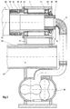
- FIG. 2 shows the structure of the engraving device according to FIG. 1 in a more detailed version in the region of the left-hand end of the screen printing cylinder 1a there. This area can also be referred to as the headstock-side area of the engraving device.
- the same elements as in Figure 1 are provided with the same reference numerals.
- the screen printing template 1 is pushed with its left end onto a slightly conical driving ring 30 belonging to the clamping head 2.
- the driving ring 30 is interchangeable and for this purpose permanently connected to a sleeve 31 which is received by the hollow shaft section 9 with a feather key connection 32. Magnets 33 hold the sleeve 31 in the axial direction.
- the hollow shaft section 9 is rotatably supported via ball bearings in the headstock housing 4 (bearing shell).
- the ball bearings 34 are braced with their inner rings 35 by means of a lock nut 36 and spacer sleeves 37 against the hollow shaft section 9.
- a V-belt drive pulley 38 is provided between the spacer sleeves 37, a feather key 39 ensuring the transmission of a drive torque to the hollow shaft section 9.
- a driver pin 40 which is connected to the hollow shaft section 9 in a torsionally rigid manner by a transverse bore, drives the rotary angle sensor 13 via a shaft 41 and a compensating coupling 42. This is supported on an angle part 43, which is mounted on the side of the flow channel 11.
- a shaft sealing ring 44 ensures a tight seal of the shaft shaft 45 protruding from the rotary angle sensor 13.
- the shaft sealing ring 44 is located in a wall 46 which forms a wall section of the flow channel which lies between the flow channel 11 and the hollow shaft section 9.
- Compressed air is transported from a blower 47 to the left end face of the hollow shaft section 9 via the flow channel 11 on the left outside of the machine bed 6 or the support device 7 and is passed through this into the screen printing stencil 1.
- the blower 47 supplies air at a pressure of up to a few tens of thousands Pa, and in such a large amount that despite the escape of this air from the openings of the screen printing stencil 1, which are exposed during the engraving work, the pressure inside the stencil remains sufficiently high .
- the blower 47 is located inside or below the machine bed 6 and is connected to the machine bed side wall 49 via a flange 48.
- the arrow 50 indicates the direction of flow of the air.
- these can have sealing side walls 51.
- the motor already mentioned bears the reference number 52 and is mounted on a carrier device 53 within the machine bed 6.
- This motor 52 drives the hollow shaft section 9 via V-belts 54 which wrap around the V-belt drive pulley 38.
- the V-belts also run around a further V-belt pulley 55, which sits on the shaft 56 of the motor 52.
- a box beam 57 connects the left end of the engraving device to its right end.
- the cross section of the box beam 57 is so large that the engraving device has sufficient rigidity and low susceptibility to vibration.
- FIG. 3 shows a section through the right end of the engraving device according to FIG. 1 on the tailstock side.
- the same parts as in FIGS. 1 and 2 are again provided with the same reference numerals.
- the tailstock 5 (right bearing shell) can be moved on guides 58 which lie on the machine bed 6 or box girder 57 and extend parallel to the longitudinal axis 25.
- the tailstock 5 is pushed so far against the screen printing stencil 1 that the conical driver ring 30 is firmly seated in the screen printing stencil 1.
- the tailstock 5 is braced in the area of its support device 8 against the guides 58 or the box girder 57, so that loosening and slipping of the tailstock 5 is not possible during operation.
- Air under increased pressure is fed on this side of the screen printing stencil 1 via a sliding rotary leadthrough 59, which is sealed against the hollow shaft section 10 by means of a long and thin gap 60.
- the non-rotatable part of the sliding rotary feedthrough 59 is carried by a holder 61 which is firmly connected to the tailstock 5 or the support device 8.
- Air is supplied from a rotary piston blower 62 (Roots blower) via a long flexible hose 12 to the interior of the screen printing stencil 1, specifically through the sliding rotary leadthrough 59 and the hollow shaft section 10.
- a rotary piston blower 62 Rooms blower
- FIG. 4 shows a schematic representation of a device according to the invention, in which there is a storage container in the flow path between the gas delivery device and the screen printing cylinder, in which there are sealing bodies which are carried along by the gas flow conveyed into the screen printing cylinder.
- the inside of the screen printing stencil 1 is continuously sealed by means of small sealing or covering bodies within the area processed by the laser beam.
- the sealing body can, for. B. small paper, plastic or metal foil sections.
- the sealing bodies can consist of small round or square pieces in the manner of confetti. Paper has the advantage of being cheap. However, there is a risk here that that portion of the laser radiation which passes through the stencil openings will also perforate the inner paper support, which would reduce the efficiency of the seal. For this reason, it may be more advantageous to use thin and reflective metal sections e.g. B. made of aluminum or nickel, which reflect the laser radiation as well as the nickel sleeve or the screen printing cylinder, which carries the outer layer of lacquer.
- the screen printing cylinder is again provided with the reference number 1a, while the lacquer layer bears the reference number 63.
- the use of thin but metallized and thus reflective plastic film as a sealing body can also be considered.
- Another possibility is to seal the openings of the stencil cylinder with small foam balls made of polystyrene, PU foam (polyurethane foam) or foamed ceramic. These balls can also have a metallic surface coating. It is essential that the sealing bodies are not melted, which could otherwise stick the template surface freed from the outer lacquer layer 63 by the laser beam again.
- Another measure can be to seal the sealing body with an evaporable liquid, e.g. B. water, slightly moistened to further seal the very narrow flow capillaries remaining between the sealing bodies. This ensures even better constancy of the internal pressure in the screen printing cylinder 1a.
- an evaporable liquid e.g. B. water
- the engraving should start from the left side of the screen printing cylinder 1a, that is from the side of the headstock 4. It continues to the right in the direction of the tailstock 5.
- the screen printing stencil 1 is to be freed from the outer lacquer layer 63 in accordance with the requirements of the pattern.
- the screen printing stencil 1 lies between a left, cone-shaped clamping head 2 on the headstock side and a right, conical clamping head 3 on the tailstock side, and is carried along by the left clamping head 2 via frictional engagement, ie set in rotation. Blower air under increased pressure is blown through the hollow shaft section 9 into the interior of the screen printing stencil 1.
- a number of further sealing bodies 65 are always released into the flow when a greater flow through the screen printing stencil 1 begins due to the exposure of openings in the screen printing cylinder 1a.
- the screen printing template 1 is so short that a double-sided Air supply can be omitted.
- the hollow shaft section 10 in the tailstock 5 is therefore closed by a cap 66. Air can now only escape from the screen printing cylinder 1a in the area 67, in which the lacquer layer 63 has already been removed.
- the sealing bodies 65 have to be removed again from the screen printing stencil 1 and best conveyed back into the storage container 64 so that they are available there for the next engraving process. This is usually done by reversing the direction of flow, i. H. Air is now sucked out of the template. With sufficiently large-area engraved screen printing stencils, there is so much open circumferential area that only a slight negative pressure is created in the stencil and this pressure is also not sufficient to bulge the stencil under the influence of the external overpressure then present. The flow rate is then also so great that the sealing body can be carried back into the reservoir 64 by the air flow.
- blower air can continue to be supplied during the sucking back phase by the tailstock 5, so that there is sufficient internal pressure in the screen printing stencil and a sufficient flow rate for returning the sealing body, now through the Hollow shaft section 9 through, is also ensured in this embodiment.
- the reservoir 64 is constructed in the manner of a cyclone.
- the flow channel 11, coming from the hollow shaft section 9, opens approximately tangentially into an opening 68 in the upper third of the storage container 64.
- the supply of sealing bodies 65 is located in the lower part of the storage container 64, that is to say in the conical part.
- air is blown through the flow channel 11a into the storage container 64, the flow channel 11a running perpendicularly to the supply of sealing bodies 65.
- the flow channel 11a thus extends concentrically to the central axis of the storage container 64 and points to its bottom surface.
- the free end of the flow channel 11a outside of the reservoir 64 is, for. B. connected to the fan 47 in Figure 2.
- the free jet which forms from the end 11b of the flow channel 11a strikes the surface of the sealing body supply and whirls up the light sealing body 65 from there, which are then carried along or carried along by the flow and into the interior via the flow channel 11 and the hollow shaft section 9 the screen printing stencil 1, where they seal the screen printing stencil 1 in the manner already described.
- the free jet can only form in the interior of the storage container 64 when air flows through the flow channel 11a in a sufficient amount. If the inside of the screen printing stencil 1 is already sealed so well that there is no appreciable flow, then no free jet is formed inside the storage container 64 and sealing bodies 65 are not entrained and are therefore not carried into the screen printing stencil 1.
- a suckback channel 69 Provided in the interior of the storage container 64 is a frustoconical sieve 70 which, starting from the flow channel 11a, is inclined downwards in the direction of the wall of the storage container 64. Because of its large dimensions, this screen 70 causes the air to flow very evenly and slowly in its area. Since the sealing bodies 65 can no longer be carried by the air when the air flow is slow, they sink downward in the storage container 64.
- the tangential confluence of the flow channel 11 in the Storage container 64 causes a vortex flow to form in the storage container 64 during the suckback phase, which supports the separation of the sealing bodies 65. The vortex flow throws the sealing body 65 against the edge of the storage container 64. Since the vertical flow component there is particularly low because of the wall friction, the sealing body 65 preferably sinks under the influence of gravity down into the storage area.
- a supply device 71 can be present between the storage container 64 and the hollow shaft section 9 in order to add a liquid medium or a powdery medium to the flow to the screen printing cylinder 1a. If water is to be supplied, a line pipe 72 ends with a nozzle in the flow channel 11. A valve 73 is opened and closed via an electromagnetic valve drive 74 if necessary.
- a powdery sealing medium is fed into the flow channel 11, e.g. B. take a screw, not shown, the transport of the powdery medium, the screw comes to rest within a transport channel that opens into the flow channel 11.
- FIG. 5 shows a somewhat different construction of a storage container 64 for sealing body 65.
- a sieve 76 in the reservoir 64 and lying horizontally causes a slow and uniform flow through the reservoir 64, on the bottom of which the sealing bodies 65 are located.
- Due to an oblique arrangement of a base plate 77 the sealing bodies 65 preferably slide into the left area of the storage container 64, where a flexible apron 78 is located.
- a channel 79 which opens tangentially into the storage container 64, is closed by a flap 80.
- the air from the channel 75 if it is let through by the screen printing stencil, which is no longer shown here, must then flow through a very narrow channel 81, which is flexibly closed by the apron 78, so that the air here has a correspondingly high speed.
- This allows the light sealing body 65 whirled up here and transported into the screen printing stencil 1 via the channel 11 already mentioned.
- the channel 79 also opens into the flow channel 11, but, as already mentioned, is now closed by the flap 80. During the suckback phase, the flap 80 opens the channel 79 and closes the lower part of the flow channel 11, which is connected to the lower end of the storage container 64.
- a vortex flow is again generated during the suckback phase, the vertical flow component of which, however, is only very small, as a result of which sealing bodies 65 thrown onto the wall of the storage container 64 slowly fall to the ground and in turn accumulate in the area of the flexible apron 78.
- the sealing bodies 65 therefore flow down through the channel 11, are deflected by the flap 80 in the direction of the channel 79 and then reach the storage container 64.
- the aforementioned feed device 71 for liquid or powdery sealing medium can be present in the region of the flow channel 11 above the flap 80.
Landscapes
- Engineering & Computer Science (AREA)
- Physics & Mathematics (AREA)
- Optics & Photonics (AREA)
- Signal Processing (AREA)
- Multimedia (AREA)
- Manufacturing & Machinery (AREA)
- Mechanical Engineering (AREA)
- Plasma & Fusion (AREA)
- General Health & Medical Sciences (AREA)
- Toxicology (AREA)
- Health & Medical Sciences (AREA)
- Thermal Sciences (AREA)
- Manufacture Or Reproduction Of Printing Formes (AREA)
- Printing Plates And Materials Therefor (AREA)
- Screen Printers (AREA)
- Printing Methods (AREA)
- Manufacturing Of Printed Wiring (AREA)
Priority Applications (7)
| Application Number | Priority Date | Filing Date | Title |
|---|---|---|---|
| AT94101572T ATE165768T1 (de) | 1994-02-02 | 1994-02-02 | Verfahren und vorrichtung zur herstellung einer siebdruckschablone |
| DE59405905T DE59405905D1 (de) | 1994-02-02 | 1994-02-02 | Verfahren und Vorrichtung zur Herstellung einer Siebdruckschablone |
| ES94101572T ES2116479T3 (es) | 1994-02-02 | 1994-02-02 | Procedimiento y dispositivo para fabricar una plantilla de serigrafia. |
| EP97118256A EP0822066A3 (fr) | 1994-02-02 | 1994-02-02 | Procédé et dispositif de fabrication d'un écran sérigraphique |
| EP94101572A EP0671261B1 (fr) | 1994-02-02 | 1994-02-02 | Procédé et dispositif de fabrication d'un écran sérigraphique |
| JP7016212A JP2739044B2 (ja) | 1994-02-02 | 1995-02-02 | シルクスクリーン印刷ステンシルを形成する方法および装置 |
| US08/382,799 US5662821A (en) | 1994-02-02 | 1995-02-02 | Method and device for producing a screen printing stencil |
Applications Claiming Priority (1)
| Application Number | Priority Date | Filing Date | Title |
|---|---|---|---|
| EP94101572A EP0671261B1 (fr) | 1994-02-02 | 1994-02-02 | Procédé et dispositif de fabrication d'un écran sérigraphique |
Related Child Applications (1)
| Application Number | Title | Priority Date | Filing Date |
|---|---|---|---|
| EP97118256A Division EP0822066A3 (fr) | 1994-02-02 | 1994-02-02 | Procédé et dispositif de fabrication d'un écran sérigraphique |
Publications (2)
| Publication Number | Publication Date |
|---|---|
| EP0671261A1 true EP0671261A1 (fr) | 1995-09-13 |
| EP0671261B1 EP0671261B1 (fr) | 1998-05-06 |
Family
ID=8215646
Family Applications (2)
| Application Number | Title | Priority Date | Filing Date |
|---|---|---|---|
| EP94101572A Revoked EP0671261B1 (fr) | 1994-02-02 | 1994-02-02 | Procédé et dispositif de fabrication d'un écran sérigraphique |
| EP97118256A Withdrawn EP0822066A3 (fr) | 1994-02-02 | 1994-02-02 | Procédé et dispositif de fabrication d'un écran sérigraphique |
Family Applications After (1)
| Application Number | Title | Priority Date | Filing Date |
|---|---|---|---|
| EP97118256A Withdrawn EP0822066A3 (fr) | 1994-02-02 | 1994-02-02 | Procédé et dispositif de fabrication d'un écran sérigraphique |
Country Status (6)
| Country | Link |
|---|---|
| US (1) | US5662821A (fr) |
| EP (2) | EP0671261B1 (fr) |
| JP (1) | JP2739044B2 (fr) |
| AT (1) | ATE165768T1 (fr) |
| DE (1) | DE59405905D1 (fr) |
| ES (1) | ES2116479T3 (fr) |
Families Citing this family (17)
| Publication number | Priority date | Publication date | Assignee | Title |
|---|---|---|---|---|
| US6076459A (en) * | 1995-01-26 | 2000-06-20 | Fingraf Ag | Method and apparatus for the production of a printing stencil |
| EP0897796B1 (fr) * | 1997-08-18 | 2000-04-26 | Schablonentechnik Kufstein Aktiengesellschaft | Procédé de fabrication d'un gabarit de sérigraphie et dispositif à cet effet |
| US6253992B1 (en) * | 1998-03-18 | 2001-07-03 | Tessera, Inc. | Solder ball placement fixtures and methods |
| DE19819571A1 (de) * | 1998-04-30 | 1999-11-04 | Giesecke & Devrient Gmbh | Wertdokument mit Sicherheitselement |
| ATE256554T1 (de) * | 1999-09-01 | 2004-01-15 | Schablonentechnik Kufstein Ag | Verfahren und vorrichtung zur herstellung eines siebdruckzylinders |
| DE10125598A1 (de) * | 2001-05-25 | 2002-12-12 | Combiflex Coating Gmbh | Verfahren und Vorrichtung zum Herstellen einer Siebdruckschablone zum Aufbringen von Klebstoff |
| DE102010027638B4 (de) * | 2010-07-19 | 2012-04-12 | Christoph Deininger | Vorrichtung zum Bearbeiten von Rohren mittels eines Laserstrahls |
| US9280641B2 (en) * | 2011-04-22 | 2016-03-08 | Vaporprint, Llc | Mechanism for remotely facilitating authorization and activation of laboratory print media labeling |
| US9126422B2 (en) | 2011-04-22 | 2015-09-08 | Vaporprint, Llc | Mechanism for labeling laboratory print media |
| CN102166688B (zh) * | 2011-05-20 | 2013-01-09 | 泉州运城制版有限公司 | 一种焊接版辊和堵头之间缝隙的方法 |
| CN102218586B (zh) * | 2011-05-20 | 2012-10-24 | 泉州运城制版有限公司 | 一种用于焊接版辊和堵头间缝隙的全自动环焊机 |
| KR101536983B1 (ko) * | 2014-02-25 | 2015-07-15 | 삼목강업주식회사 | 스프링용 레이저 마킹 시스템 |
| FR3045053B1 (fr) | 2015-12-09 | 2018-01-05 | Cisbio Bioassays | Agents complexants hydrosolubles a base de triazapyridinophane et complexes de lanthanide fluorescents correspondants |
| CN109514110B (zh) * | 2018-12-29 | 2023-10-20 | 江门职业技术学院 | 一种激光雕刻印花工艺及实施该工艺的设备 |
| US20230136690A1 (en) * | 2020-04-10 | 2023-05-04 | Alphanov | Laser turning system, laser turning method, and part obtained by using such a system |
| CN111468842A (zh) * | 2020-05-28 | 2020-07-31 | 宁波飞图自动技术有限公司 | 一种包装容器辅助检测的切割方法及设备 |
| US20230286082A1 (en) * | 2022-03-11 | 2023-09-14 | Ats Industrial Automation Inc. | Laser cleaning of oxidized parts |
Citations (4)
| Publication number | Priority date | Publication date | Assignee | Title |
|---|---|---|---|---|
| FR2417033A1 (fr) * | 1978-02-14 | 1979-09-07 | Buser Ag Maschf Fritz | Dispositif pour mise sous contrainte de cylindre metallique a paroi mince |
| DE3601327A1 (de) * | 1985-02-12 | 1986-08-14 | Schablonentechnik Kufstein GmbH, Kufstein | Verfahren und vorrichtung zur herstellung einer siebdruckschablone |
| EP0320137A1 (fr) * | 1987-11-25 | 1989-06-14 | Zed Instruments Limited | Appareil pour la gravure au laser pour la fabrication d'écrans sérigraphiques cylindriques |
| EP0338612A1 (fr) * | 1988-04-16 | 1989-10-25 | Stork X-Cel B.V. | Procédé et appareil pour la fabrication de stencils pour l'impression rotative sérigraphique |
Family Cites Families (10)
| Publication number | Priority date | Publication date | Assignee | Title |
|---|---|---|---|---|
| AT299266B (de) * | 1967-07-26 | 1972-06-12 | Johannes Zimmer | Druckzylinder |
| US3707749A (en) * | 1970-10-12 | 1973-01-02 | Gen Tire & Rubber Co | Variable pressure bed roller |
| JPS5269091A (en) * | 1975-12-05 | 1977-06-08 | Nec Corp | Laser working device |
| JPS6117391A (ja) * | 1984-07-03 | 1986-01-25 | Mitsubishi Heavy Ind Ltd | レ−ザ切断法 |
| JPS6221496A (ja) * | 1985-07-23 | 1987-01-29 | Mitsubishi Electric Corp | レ−ザ切断加工機 |
| JPH0299287A (ja) * | 1988-09-30 | 1990-04-11 | Suzuki Motor Co Ltd | シリンダスリーブの加工方法 |
| US5198636A (en) * | 1989-11-07 | 1993-03-30 | Schablonentechnik Kufstein Gesellschaft Mbh | Apparatus for machining a hollow cylinder to produce a pattern drum |
| WO1993010939A1 (fr) * | 1991-12-04 | 1993-06-10 | Colorado Laser Marking, Inc. | Appareil et procede de marquage de tubes a paroi mince |
| DE59202410D1 (de) * | 1992-03-27 | 1995-07-06 | Kufstein Schablonentech Gmbh | Vorrichtung zum Bearbeiten dünnwandiger Hohlzylinder mittels eines Laserstrahls. |
| DE59202409D1 (de) * | 1992-03-27 | 1995-07-06 | Kufstein Schablonentech Gmbh | Vorrichtung zum Bearbeiten dünnwandiger Hohlzylinder mittels eines Laserstrahls. |
-
1994
- 1994-02-02 EP EP94101572A patent/EP0671261B1/fr not_active Revoked
- 1994-02-02 EP EP97118256A patent/EP0822066A3/fr not_active Withdrawn
- 1994-02-02 AT AT94101572T patent/ATE165768T1/de not_active IP Right Cessation
- 1994-02-02 ES ES94101572T patent/ES2116479T3/es not_active Expired - Lifetime
- 1994-02-02 DE DE59405905T patent/DE59405905D1/de not_active Revoked
-
1995
- 1995-02-02 US US08/382,799 patent/US5662821A/en not_active Expired - Fee Related
- 1995-02-02 JP JP7016212A patent/JP2739044B2/ja not_active Expired - Fee Related
Patent Citations (4)
| Publication number | Priority date | Publication date | Assignee | Title |
|---|---|---|---|---|
| FR2417033A1 (fr) * | 1978-02-14 | 1979-09-07 | Buser Ag Maschf Fritz | Dispositif pour mise sous contrainte de cylindre metallique a paroi mince |
| DE3601327A1 (de) * | 1985-02-12 | 1986-08-14 | Schablonentechnik Kufstein GmbH, Kufstein | Verfahren und vorrichtung zur herstellung einer siebdruckschablone |
| EP0320137A1 (fr) * | 1987-11-25 | 1989-06-14 | Zed Instruments Limited | Appareil pour la gravure au laser pour la fabrication d'écrans sérigraphiques cylindriques |
| EP0338612A1 (fr) * | 1988-04-16 | 1989-10-25 | Stork X-Cel B.V. | Procédé et appareil pour la fabrication de stencils pour l'impression rotative sérigraphique |
Also Published As
| Publication number | Publication date |
|---|---|
| US5662821A (en) | 1997-09-02 |
| EP0671261B1 (fr) | 1998-05-06 |
| JPH0834107A (ja) | 1996-02-06 |
| JP2739044B2 (ja) | 1998-04-08 |
| EP0822066A2 (fr) | 1998-02-04 |
| ATE165768T1 (de) | 1998-05-15 |
| ES2116479T3 (es) | 1998-07-16 |
| DE59405905D1 (de) | 1998-06-10 |
| EP0822066A3 (fr) | 1998-03-25 |
Similar Documents
| Publication | Publication Date | Title |
|---|---|---|
| EP0671261B1 (fr) | Procédé et dispositif de fabrication d'un écran sérigraphique | |
| EP0427004B1 (fr) | Appareil pour le traitement d'un cylindre creux avec un laser | |
| DE1268784B (de) | Verfahren und Vorrichtung zum Aufbringen einer UEberzugsschicht auf insbesondere pharmazeutische Tabletten | |
| DD241567A5 (de) | Verfahren und Vorrichtung zur Herstellung einer Siebdruckschablone | |
| EP1727673B1 (fr) | Systeme d'aspiration pour un dispositif servant a structurer une surface d'une piece a usiner au moyen d'un rayonnement | |
| DE102022134674A1 (de) | Laserrolltrommel und Maschine der Tabak verarbeitenden Industrie | |
| EP0590164B1 (fr) | Procédé et dispositif pour fabriquer des matrices d'impression par stencil | |
| EP0562149B1 (fr) | Appareil d'usinage d'un cylindre creuse à paroi mince par un laser | |
| EP0562150B1 (fr) | Appareil d'usinage de cylindre creus à paroi mince par un laser | |
| EP0590165A1 (fr) | Buse électrostatique, en particulier pour injecter des matériaux fluides à haute viscosité | |
| DE19840934B4 (de) | Anordnung zum Entfernen von Material, das durch eine Laserstrahlungsquelle bei der Materialbearbeitung von einer Bearbeitungsfläche abgetragen wird | |
| EP0818711B1 (fr) | Procédé et appareil pour la fabrication de plaques d'impression flexographiques | |
| DE19744435C2 (de) | Vorrichtung zum Erhöhen der Oberflächenfestigkeit von metallischen Komponenten | |
| EP2669088A1 (fr) | Dispositif d'obturation pour têtes d'impression | |
| DE29816109U1 (de) | Anordnung zum Entfernen von Material, das durch eine Laserstrahlungsquelle bei der Materialbearbeitung von einer Bearbeitungsfläche abgetragen wird | |
| EP0802047B1 (fr) | Pochoir à demi-tons et procédé et dispositif pour sa fabrication | |
| DE68903035T2 (de) | Trommel zum klemmen blattfoermiger unterlagen und farbstrahldrucker damit versehen. | |
| EP0622190B1 (fr) | Dispositif pour fixer d'une manière rigide un cylindre creux à parois minces | |
| DE10016534C2 (de) | Verfahren und Vorrichtung zum Staubschutz in einer Laserbearbeitungsvorrichtung | |
| DE102011005908A1 (de) | Drucksysteme mit fortschreitendem Bildtransfer und fortschreitender Strahlungsenergiebeaufschlagung von Bildern für das Drucken mit Mehrfachdurchlauf, für entsprechende Druckvorrichtungen und zugehörige Verfahren | |
| EP0728577A1 (fr) | Procédé pour le traitement d'un cylindre creux | |
| EP1080885B1 (fr) | Procédé et appareil pour la réalisation de pochoirs cylindriques | |
| DE1909016A1 (de) | Vorrichtung zur Beschleunigung fliessfaehiger,insbesondere koerniger Substanzen | |
| DE202018006038U1 (de) | Vorrichtung zum Entgasen eines flüssigen bis pastösen Mediums, insbesondere einer Streichfarbe | |
| EP0436754A1 (fr) | Cylindre peigneur pour une machine de filature à bout libre |
Legal Events
| Date | Code | Title | Description |
|---|---|---|---|
| PUAI | Public reference made under article 153(3) epc to a published international application that has entered the european phase |
Free format text: ORIGINAL CODE: 0009012 |
|
| 17P | Request for examination filed |
Effective date: 19950117 |
|
| AK | Designated contracting states |
Kind code of ref document: A1 Designated state(s): AT BE CH DE DK ES FR GB GR IE IT LI LU MC NL PT SE |
|
| 17Q | First examination report despatched |
Effective date: 19960221 |
|
| GRAG | Despatch of communication of intention to grant |
Free format text: ORIGINAL CODE: EPIDOS AGRA |
|
| GRAG | Despatch of communication of intention to grant |
Free format text: ORIGINAL CODE: EPIDOS AGRA |
|
| GRAH | Despatch of communication of intention to grant a patent |
Free format text: ORIGINAL CODE: EPIDOS IGRA |
|
| GRAH | Despatch of communication of intention to grant a patent |
Free format text: ORIGINAL CODE: EPIDOS IGRA |
|
| GRAA | (expected) grant |
Free format text: ORIGINAL CODE: 0009210 |
|
| AK | Designated contracting states |
Kind code of ref document: B1 Designated state(s): AT CH DE ES FR GB IT LI LU NL SE |
|
| REF | Corresponds to: |
Ref document number: 165768 Country of ref document: AT Date of ref document: 19980515 Kind code of ref document: T |
|
| XX | Miscellaneous (additional remarks) |
Free format text: TEILANMELDUNG 97118256.3 EINGEREICHT AM 21/10/97. |
|
| REG | Reference to a national code |
Ref country code: CH Ref legal event code: EP |
|
| GBT | Gb: translation of ep patent filed (gb section 77(6)(a)/1977) |
Effective date: 19980506 |
|
| REF | Corresponds to: |
Ref document number: 59405905 Country of ref document: DE Date of ref document: 19980610 |
|
| REG | Reference to a national code |
Ref country code: ES Ref legal event code: FG2A Ref document number: 2116479 Country of ref document: ES Kind code of ref document: T3 |
|
| ET | Fr: translation filed | ||
| ITF | It: translation for a ep patent filed | ||
| PG25 | Lapsed in a contracting state [announced via postgrant information from national office to epo] |
Ref country code: SE Free format text: LAPSE BECAUSE OF FAILURE TO SUBMIT A TRANSLATION OF THE DESCRIPTION OR TO PAY THE FEE WITHIN THE PRESCRIBED TIME-LIMIT Effective date: 19980806 |
|
| PG25 | Lapsed in a contracting state [announced via postgrant information from national office to epo] |
Ref country code: LU Free format text: LAPSE BECAUSE OF NON-PAYMENT OF DUE FEES Effective date: 19990202 |
|
| PLBQ | Unpublished change to opponent data |
Free format text: ORIGINAL CODE: EPIDOS OPPO |
|
| PLBI | Opposition filed |
Free format text: ORIGINAL CODE: 0009260 |
|
| PLBF | Reply of patent proprietor to notice(s) of opposition |
Free format text: ORIGINAL CODE: EPIDOS OBSO |
|
| 26 | Opposition filed |
Opponent name: CST-GMBH Effective date: 19990204 |
|
| NLR1 | Nl: opposition has been filed with the epo |
Opponent name: CST-GMBH |
|
| PLBF | Reply of patent proprietor to notice(s) of opposition |
Free format text: ORIGINAL CODE: EPIDOS OBSO |
|
| PLBF | Reply of patent proprietor to notice(s) of opposition |
Free format text: ORIGINAL CODE: EPIDOS OBSO |
|
| PGFP | Annual fee paid to national office [announced via postgrant information from national office to epo] |
Ref country code: DE Payment date: 20010223 Year of fee payment: 8 |
|
| RDAH | Patent revoked |
Free format text: ORIGINAL CODE: EPIDOS REVO |
|
| REG | Reference to a national code |
Ref country code: GB Ref legal event code: IF02 |
|
| PGFP | Annual fee paid to national office [announced via postgrant information from national office to epo] |
Ref country code: GB Payment date: 20020206 Year of fee payment: 9 |
|
| PGFP | Annual fee paid to national office [announced via postgrant information from national office to epo] |
Ref country code: CH Payment date: 20020218 Year of fee payment: 9 |
|
| PGFP | Annual fee paid to national office [announced via postgrant information from national office to epo] |
Ref country code: AT Payment date: 20020220 Year of fee payment: 9 |
|
| PGFP | Annual fee paid to national office [announced via postgrant information from national office to epo] |
Ref country code: FR Payment date: 20020227 Year of fee payment: 9 |
|
| PGFP | Annual fee paid to national office [announced via postgrant information from national office to epo] |
Ref country code: NL Payment date: 20020228 Year of fee payment: 9 |
|
| PGFP | Annual fee paid to national office [announced via postgrant information from national office to epo] |
Ref country code: ES Payment date: 20020311 Year of fee payment: 9 |
|
| RDAG | Patent revoked |
Free format text: ORIGINAL CODE: 0009271 |
|
| STAA | Information on the status of an ep patent application or granted ep patent |
Free format text: STATUS: PATENT REVOKED |
|
| 27W | Patent revoked |
Effective date: 20011206 |
|
| GBPR | Gb: patent revoked under art. 102 of the ep convention designating the uk as contracting state |
Free format text: 20011206 |
|
| REG | Reference to a national code |
Ref country code: CH Ref legal event code: PL |
|
| NLR2 | Nl: decision of opposition |