EP0671604A1 - Vorrichtung zur Umwandlung einer mechanischen in eine elektrische Grösse - Google Patents
Vorrichtung zur Umwandlung einer mechanischen in eine elektrische Grösse Download PDFInfo
- Publication number
- EP0671604A1 EP0671604A1 EP95102859A EP95102859A EP0671604A1 EP 0671604 A1 EP0671604 A1 EP 0671604A1 EP 95102859 A EP95102859 A EP 95102859A EP 95102859 A EP95102859 A EP 95102859A EP 0671604 A1 EP0671604 A1 EP 0671604A1
- Authority
- EP
- European Patent Office
- Prior art keywords
- conductor tracks
- deflection
- signals
- resolution
- contact pair
- Prior art date
- Legal status (The legal status is an assumption and is not a legal conclusion. Google has not performed a legal analysis and makes no representation as to the accuracy of the status listed.)
- Granted
Links
Images

Classifications
-
- G—PHYSICS
- G06—COMPUTING OR CALCULATING; COUNTING
- G06F—ELECTRIC DIGITAL DATA PROCESSING
- G06F3/00—Input arrangements for transferring data to be processed into a form capable of being handled by the computer; Output arrangements for transferring data from processing unit to output unit, e.g. interface arrangements
- G06F3/01—Input arrangements or combined input and output arrangements for interaction between user and computer
- G06F3/03—Arrangements for converting the position or the displacement of a member into a coded form
- G06F3/041—Digitisers, e.g. for touch screens or touch pads, characterised by the transducing means
-
- G—PHYSICS
- G01—MEASURING; TESTING
- G01D—MEASURING NOT SPECIALLY ADAPTED FOR A SPECIFIC VARIABLE; ARRANGEMENTS FOR MEASURING TWO OR MORE VARIABLES NOT COVERED IN A SINGLE OTHER SUBCLASS; TARIFF METERING APPARATUS; MEASURING OR TESTING NOT OTHERWISE PROVIDED FOR
- G01D5/00—Mechanical means for transferring the output of a sensing member; Means for converting the output of a sensing member to another variable where the form or nature of the sensing member does not constrain the means for converting; Transducers not specially adapted for a specific variable
- G01D5/12—Mechanical means for transferring the output of a sensing member; Means for converting the output of a sensing member to another variable where the form or nature of the sensing member does not constrain the means for converting; Transducers not specially adapted for a specific variable using electric or magnetic means
-
- G—PHYSICS
- G01—MEASURING; TESTING
- G01D—MEASURING NOT SPECIALLY ADAPTED FOR A SPECIFIC VARIABLE; ARRANGEMENTS FOR MEASURING TWO OR MORE VARIABLES NOT COVERED IN A SINGLE OTHER SUBCLASS; TARIFF METERING APPARATUS; MEASURING OR TESTING NOT OTHERWISE PROVIDED FOR
- G01D5/00—Mechanical means for transferring the output of a sensing member; Means for converting the output of a sensing member to another variable where the form or nature of the sensing member does not constrain the means for converting; Transducers not specially adapted for a specific variable
- G01D5/12—Mechanical means for transferring the output of a sensing member; Means for converting the output of a sensing member to another variable where the form or nature of the sensing member does not constrain the means for converting; Transducers not specially adapted for a specific variable using electric or magnetic means
- G01D5/25—Selecting one or more conductors or channels from a plurality of conductors or channels, e.g. by closing contacts
- G01D5/252—Selecting one or more conductors or channels from a plurality of conductors or channels, e.g. by closing contacts a combination of conductors or channels
Definitions
- the invention relates to a device for converting an at least one-dimensional mechanical deflection into an electrical variable corresponding to this deflection.
- This device was designed as a two-dimensional position meter, display or position setpoint device for an area of a few square centimeters.
- setpoint devices are used, for example, for remote control purposes as a “mouse” or “trackball” in computer technology or as a “joystick” in model making.
- the basic structure of a “mouse” or a “trackball” consists of two orthogonally arranged incremental rotary encoders and a rubberized ball rotatably mounted in a mounting bracket, which rests on both rotary encoder axes. By rotating the ball in any direction, either one or both rotary encoder axes are changed at the same time, so that the angle of the rotational movement of the ball corresponds to a specific change in the rotation of the rotary encoder.
- a signal processing stage for evaluation is usually connected downstream of the pulse-generating encoders.
- a "joystick” has two potentiometers instead of the rotary encoders, which are coupled to a control lever via a cardanic deflection. A corresponding position of the potentiometer wipers is assigned to each position of the control lever, so that the voltage values picked up at the potentiometer terminals can be fed to an evaluation circuit.
- a disadvantage of both of the above concepts is both the relatively high production costs (material and manufacture) and the high energy consumption.
- the invention has for its object to develop a positioning and position measuring device which has an inexpensive production option and an extremely low energy consumption (theoretically none) with a sufficiently high resolution.
- a device for converting an at least one-dimensional mechanical deflection into an electrical quantity corresponding to this deflection in which one end of a sliding contact pair is actuated with electrical control signals via at least two contact surfaces, the other end of the sliding contact pair is actuated via a number required for a specific resolution parallel conductor tracks are shifted, and by moving the pair of sliding contacts, the control signals are forwarded via the contacted conductor tracks at their end as evaluation signals.
- the control signal is advantageously passed on theoretically without loss and unaffected by the connections of the contact surfaces via the wipers and via the conductor tracks contacted by the wipers to their ends.
- An additional, positive aspect is the cost-effective production of the contact areas and the conductor tracks on a carrier material. For example, it can be manufactured on a copper-clad printed circuit board in just one operation.
- a sensible extension of the device is to increase the number of conductor tracks routed at right angles to one another in accordance with the specific requirements.
- the advantage is that the resolution increases with the same number of conductor tracks.
- the limit of the resolution actually lies only in the structural fineness of the conductor tracks, the mechanical precision of the sliding contact pair and / or in the dimensions of the device.
- control of the contact areas and the evaluation of the evaluation signals can be carried out, for example, by a microprocessor.
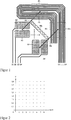
- the position sensor in FIG. 1 has four rectangular contact areas A1 to A4 and eight parallel, meandering conductor tracks L1 to L8.
- Two wipers SK mounted on a carrier TR, each with two contacts, bridge two of the four contact areas A1 to A4 with one, two or none of the conductor tracks L1 to L8, which are located within the area sections F1 to F4 assigned to the contact areas A1 to A4 and shown in broken lines located on the meander.
- the sliding contact carrier TR is suspended in such a way that it can be moved in parallel in both the X and Y directions, and its rotation with respect to the eight conductor tracks L1 to L8 must be excluded.
- a parallel displacement of the contact carrier in the X / Y plane establishes an electrical connection between two of the areas A1 to A4 and one, two or none of the conductor tracks L1 to L8 in the assigned area section F1 to F4.
- the amplitude of the steering can now be determined via the eight conductor tracks. Should two of the lines L1 to L8 be bridged due to the sliding contact SK being too wide the higher-order line is evaluated in this exemplary embodiment. This determination is made arbitrarily and can also be carried out with the lower value. It is also possible to start the evaluation either with line L1 or with line L8.
- the position sensor can be controlled and evaluated particularly advantageously with the aid of a processor.
- the four rectangular contact areas A1 to A4 are connected via a control line S1 to S4 to an output port and the eight measuring lines L1 to L8 to an input port of the microprocessor.
- the four contact areas A1 to A4 are now individually set to logic one in a sequence that can be defined by the user, after which it is determined at the input port whether and which of the conductor tracks L1 to L8 forwards this logic one (high level).
- This method has the advantage that the same eight conductor tracks can be used for the resolution of the deflection in both dimensions including the sign.
- the respective three non-active contact areas must be switched to high impedance by the processor, otherwise, when the sliding contact SK is deflected in the direction of the bisector (45 °), the high level of a contact area is short-circuited via both sliders and a contact area at low level to ground .
- FIG. 3 gives an overview of a sequence control.
- the evaluation by the processor is carried out by serial testing of all eight lines L1 to L8 for a high level.
- Each of these eight lines in this exemplary embodiment of the sequential control system starting with L8, is assigned a four-bit data word which, when the line is high, is stored individually in a register of the processor together with the sign bit for each dimension.
- the two four-bit data words of both dimensions now become an eight-bit data word without taking the signs into account composed. This can either be evaluated directly, or a table in a ROM of the controlling processor can advantageously be addressed with it.
- the sign determination is carried out under software control when the control lines S1 to S4 are activated, since each contact surface pair can be assigned a specific quadrant in its specific pairing.
- this position sensor is used, for example, in an infrared remote control transmitter for TV sets, when the sliding contact carrier is actuated, a controlled cursor on a TV screen runs at a more or less high speed on the one with the sliding contact carrier beforehand on a TV screen certain position.
- This position meter, positioning and position setpoint generator can be used for a wide range of applications in control technology.
Landscapes
- Physics & Mathematics (AREA)
- General Physics & Mathematics (AREA)
- Engineering & Computer Science (AREA)
- General Engineering & Computer Science (AREA)
- Theoretical Computer Science (AREA)
- Human Computer Interaction (AREA)
- Measurement Of Length, Angles, Or The Like Using Electric Or Magnetic Means (AREA)
- Position Input By Displaying (AREA)
- Transmission And Conversion Of Sensor Element Output (AREA)
- Length Measuring Devices With Unspecified Measuring Means (AREA)
Abstract
Description
- Die Erfindung betrifft eine Vorrichtung zur Umwandlung einer mindestens eindimensionalen mechanischen Auslenkung in eine dieser Auslenkung entsprechende elektrische Größe.
- Diese Vorrichtung wurde als zweidimensionaler Positionsmesser, Anzeige- oder Lage-Sollwertgeber für eine Fläche von wenigen Quadratzentimetern konzipiert.
- Bekannte Ausführungsformen von Sollwertgeber werden zum Beispiel zu Fernsteuerungszwecken als "Mouse" bzw. "Trackball" in der Computertechnik oder als "Joystick" im Modellbau eingesetzt.
Der prinzipielle Aufbau einer "Mouse" bzw. eines "Trackball" besteht aus zwei ortogonal angeordneten Inkremental-Drehgebern und einem in einer Aufnahmehalterung drehbar gelagerten, gummierten Ball, der an beiden Drehgeberachsen anliegt. Durch Drehung des Balles in eine beliebige Richtung, werden entweder eine oder beide Drehgeberachsen gleichzeitig verändert, so daß dem Winkel der Drehbewegung des Balles eine bestimmte Umdrehungsveränderung des Drehgebers entspricht. Den Impulse liefernden Drehgebern ist gewöhnlich eine signalverarbeitende Stufe zur Auswertung nachgeschaltet. - Ein "Joystick" weist anstelle der Drehgeber zwei Potentiometer auf, die über eine kardanische Umlenkung mit einem Steuerhebel verkoppelt sind. Jeder Position des Steuerhebels ist eine dementsprechende Stellung der Potentiometerschleifer zugeordnet, so daß die an den Potentiometerklemmen abgegriffenen Spannungswerte einer Auswerteschaltung zugeführt werden können.
- Nachteilig bei beiden oben angeführten Konzepten sind sowohl die relativ hohen Produktionskosten (Material sowie Herstellung) als auch die hohe Energieaufnahme.
- Der Erfindung liegt die Aufgabe zugrunde, eine Positionier- und Lagemeßvorrichtung zu entwickeln, die eine kostengünstige Produktionsmöglichkeit und eine äußerst geringe Energieaufnahme (theoretisch keine) bei gleichzeitig ausreichend hoher Auflösung aufweist.
- Diese Aufgabe wird gelöst durch eine Vorrichtung nach Anspruch 1. Vorteilhafte Weiterbildungen sind in den Unteransprüchen angegeben.
- Erfindungsgmäß wird eine Vorrichtung zur Umwandlung einer mindestens eindimensionalen mechanischen Auslenkung in eine dieser Auslenkung entsprechende elektrische Größe vorgeschlagen, bei der über wenigstens zwei Kontaktflächen ein Ende eines Schleifkontaktpaares mit elektrischen Ansteuersignalen angesteuert wird, das andere Ende des Schleifkontaktpaares über eine für eine bestimmte Auflösung erforderliche Anzahl von parallel geführten Leiterbahnen verschoben wird, und durch die Verschiebung des Schleifkontaktpaares die Ansteuersignale über die kontaktierten Leiterbahnen an deren Ende als Auswertesignale weitergeleitet werden.
Mit dieser Vorrichtung wird vorteilhafterweise das Ansteuersignal theoretisch verlustlos und unbeeinflußt von den Anschlüssen der Kontaktflächen über die Schleifer und über die von den Schleifern kontaktierten Leiterbahnen zu deren Enden weitergeleitet. Ein zusätzlicher, positiver Gesichtspunkt ist die kostengünstige Produktion der Kontaktflächen sowie der Leiterbahnen auf einem Trägermaterial. Die Herstellung kann zum Beispiel auf einer kupferkaschierten Leiterplatte in nur einem Arbeitsgang erfolgen. - Werden die parallel verlaufenden Leiterbahnen auf dem Trägermaterial im rechten Winkel zueinander weitergeführt, so ist es möglich, nicht nur eine Dimension sondern zwei Dimensionen gleichzeitig abzutasten und zu bestimmen.
- Eine sinnvolle Erweiterung der Vorrichtung besteht darin, die Anzahl der rechtwinklig zueinander geführten Leiterbahnen den spezifischen Anforderungen entsprechend zu erhöhen.
Der Vorteil liegt darin, daß mit steigender Anzahl von Leiterbahnen in gleichem Maße die Auflösung steigt. Die Grenze der Auflösung liegt eigentlich nur in der Strukturfeinheit der Leiterbahnen, der mechanischen Präzision des Schleifkontaktpaares und/oder in den Ausmaßen der Vorrichtung. - Es empfiehlt sich die Aufbringung zweier weiterer Kontaktflächen zur Unterteilung des Abtastbereiches in insgesamt vier Abschnitte. Desweiteren sollte eine bevorzugte Anordnung der Leiterbahnen derart vorgenommen werden, daß die Leiterbahnen in einem engen 180°- Bogen wieder parallel zu den bereits bestehenden Leiterbahnen zurückgeführt werden.
Der entscheidende Vorteil zweier zusätzlicher Kontaktflächen sowie der Leiterbahnrückführung liegt in der Erkennung des positiven wie auch negativen X-/Y-Bereichs und damit verbunden eine Ansteuerbarkeit einzelner Positionspunkte, die um das 4-fache höher liegt als bei einfacher Leiterbahnführung. - Die Ansteuerung der Kontaktflächen sowie die Auswertung der Auswertesignale, die an dem einen oder dem anderen Ende der Leiterbahnen abgegriffen werden können, kann beispielsweise von einem Mikroprozessor übernommen werden.
- Die Erfindung wird im folgenden in einem Ausführungsbeispiel anhand der Figuren näher erläutert. Dabei zeigen
- Figur 1
- einen Positionsmesser mit Erkennung des positiven wie negativen X-/Y-Bereichs;
- Figur 2
- ein Punktegitter der adressierbaren Positionen je Quadrant;
- Figur 3
- ein Flußdiagramm eines Steuerprogramms für einen Positionsmesser;
- Wie in Figur 2 gezeigt läßt sich in einem kartesischen Koordinatensystem ein Punktegitter mit ganzzahligen Koordinaten darstellen. Insgesamt handelt es sich hierbei um 9 x 9 = 81 Positionen für nur einen Quadranten oder 17 x 17 = 289 Positionen für alle vier Quadranten.
- Der Positionsmesser in Figur 1 weist vier rechteckige Kontaktflächen A1 bis A4 sowie acht parallel liegende, mäanderförmig geführte Leiterbahnen L1 bis L8 auf. Zwei auf einem Träger TR aufgebrachte Schleifer SK mit je zwei Kontakten überbrücken dabei zwei der vier Kontaktflächen A1 bis A4 mit einer, zwei oder keiner der Leiterbahnen L1 bis L8, die sich innerhalb der den Kontaktfflächen A1 bis A4 zugeordneten, gestrichelt dargestellten Flächenabschnitte F1 bis F4 auf dem Leiterbahnmäander befinden.
- Der Schleifkontaktträger TR sei so aufgehängt, daß er sich sowohl in X- als auch in Y-Richtung parallel verschieben läßt, wobei seine Verdrehung bezüglich der acht Leiterbahnen L1 bis L8 ausgeschlossen sein muß.
- Eine Parallelverschiebung des Kontaktträgers in der X-/Y-Ebene stellt eine elektrische Verbindung zwischen zwei der Flächen A1 bis A4 und einer, zwei oder keiner der Leiterbahnen L1 bis L8 im zugeordneten Flächenabschnitt F1 bis F4 her. Über die acht Leiterbahnen Läßt sich nun die Amplitude der Aus Lenkung ermitteln. Sollten aufgrund eines zu breiten Schleifkontaktes SK zwei der Leitungen L1 bis L8 überbrückt werden, so wird in diesem Ausführungsbeispiel die höherwertige Leitung ausgewertet. Diese Festlegung ist willkürlich getroffen und kann auch mit der niederwertigeren durchgeführt werden. Genausogut besteht die Möglichkeit die Auswertung entweder mit der Leitung L1 oder mit der Leitung L8 zu beginnen.
- Der Positionsmesser Läßt sich mit Hilfe eines Prozessors besonders vorteilhaft ansteuern und auswerten. Dazu werden die vier rechteckigen Kontaktflächen A1 bis A4 über je eine Steuerleitung S1 bis S4 an ein Ausgabeport sowie die acht Meßleitungen L1 bis L8 an ein Eingabeport des Mikroprozessors angeschlossen. Im Zeitmultiplexverfahren werden nun die vier Kontaktflächen A1 bis A4 in einer vom Anwender beliebig festlegbaren Reihenfolge einzeln auf logisch Eins gesetzt, worauf am Eingabeport festgestellt wird, ob und welche der Leiterbahnen L1 bis L8 diese Logische Eins (High-Pegel) weiterleitet.
Dieses Verfahren hat den Vorteil, daß für die Auflösung der Auslenkung in beide Dimensionen inklusive der Vorzeichen dieselben acht Leiterbahnen benutzt werden können. Die jeweiligen drei nicht aktiven Kontaktflächen müssen vom Prozessor allerdings hochohmig geschaltet werden, andernfalls bei einer Auslenkung des Schleifkontaktes SK in Richtung der Winkelhalbierenden (45°) der High-Pegel einer Kontaktfläche über beide Schleifer und eine auf Low-Pegel Liegende Kontaktfläche gegen Masse kurzgeschlossen wird. - Figur 3 gibt einen Überblick über eine Ablaufsteuerung. Die Auswertung durch den Prozessor erfolgt durch serielle Prüfung aller acht Leitungen L1 bis L8 hinsichtlich eines High-Pegels. Jede dieser acht Leitungen, in diesem Ausführungsbeispiel der Ablaufsteuerung beginnend mit L8, bekommt ein Vierbit-Datenwort zugeordnet, welches bei einem High-Pegel der Leitung zusammen mit dem Vorzeichenbit für jede Dimension in einem Register des Prozessors einzeln abgespeichert wird.
Aus den beiden Vierbit-Datenwörtern beider Dimensionen wird nun ohne Berücksichtigung der Vorzeichen ein Achtbitdatenwort zusammengesetzt. Dieses kann entweder direkt ausgewertet oder es kann damit zweckmäßigerweise eine Tabelle in einem ROM des ansteuernden Prozessors adressiert werden. Die Vorzeichenbestimmung erfolgt softwaregesteuert bereits bei der Ansteuerung der Steuerleitungen S1 bis S4, da jedem Kontaktflächenpaar in seiner spezifischen Paarung ein bestimmter Quadrant zugeordnet werden kann.
Soll eine Winkelmessung durchgeführt werden, so beruht diese ebenfalls auf einer softwaremäßig durchgeführten Polarkoordinatentransformation. Dazu wird wiederum eine Tabelle im ROM des ansteuernden Prozessors abgelegt, die nun durch die X- und Y-Koordinaten des Schleifkontaktpaares SK indirekt adressiert wird. In dieser Tabelle kann nun ein jedem Gitterpunkt zugeordneter Winkel mit einer vom Charakter der Tabelle abhängigen Auflösung abgelegt werden. In einer zweiten Tabelle, die über einen Offset auf die ursprüngliche Adresse erreicht wird, kann dazu eine Information über den Betrag eines Geschwindigkeitssvektors abgelegt sein, die neben der Winkelinformation als zusätzliches Datenwort übertragen werden kann.
Ist dieser Positionsmesser beispielsweise in einem Infrarot-Fernbedienungsgeber für TV-Geräte eingesetzt, läuft bei Betätigung des Schleifkontakträgers in eine beliebige Richtung und auf einen bestimmten Punkt hin ein angesteuerter Cursor auf einem TV-Bildschirm mit mehr oder minder hoher Geschwindigkeit auf die mit dem Schleifkontaktträger zuvor bestimmte Position.
Dieser Positionsmesser, Positionier- und Lage-Sollwertgeber läßt sich für ein breites Anwendungsspektrum in der Steuerungs- und Regelungstechnik einsetzen.
Claims (7)
- Vorrichtung zur Umwandlung einer mindestens eindimensionalen mechanischen Auslenkung in eine dieser Auslenkung entsprechende elektrische Größe dadurch gekennzeichnet, daß über wenigstens zwei Kontaktflächen (A1, A4) ein Ende eines Schleifkontaktpaares (SK) mit elektrischen Ansteuersignalen (S1, S4) angesteuert wird, daß das andere Ende des Schleifkontaktpaares (SK) über eine für eine bestimmte Auflösung erforderliche Anzahl von parallel geführten Leiterbahnen innerhalb eines Flächenabschnitts (F1, F4) verschoben wird, und daß durch die Verschiebung des Schleifkontaktpaares (SK) die Ansteuersignale über die kontaktierten Leiterbahnen (L1 bis L8) als Auswertesignale weitergeleitet werden.
- Vorrichtung nach Anspruch 1 dadurch gekennzeichnet, daß für die Auflösung der mechanischen Auslenkung in zwei Dimensionen dieselben Leiterbahnen benutzt werden, wie für die Auslenkung in eine Dimension.
- Vorrichtung nach einem der Ansprüche 1 bis 2 dadurch gekennzeichnet, daß eine Erhöhung oder Verringerung der Anzahl der Leiterbahnen eine dementsprechend hohe oder geringe Auflösung ergibt.
- Vorrichtung nach einem der Ansprüche 1 bis 3 dadurch gekennzeichnet, daß durch Aufbringung von zwei weiteren paarweise angeordneten Kontaktflächen (A2, A3) die Auflösung der mechanischen Auslenkung in zwei Dimensionen sowohl in positiver als auch in negativer Richtung erolgt.
- Vorrichtung nach einem der Ansprüche 1 bis 4 dadurch gekennzeichnet, daß durch Umlenkung um 180° und Rückführung der parallel verlaufenden Leiterbahnen (L1, L8) die Ansteuerbarkeit einzelner Positionspunkte um das Vierfache höher Liegt.
- Vorrichtung nach einem der Ansprüche 1 bis 5 dadurch gekennzeichnet, daß die Ansteuersignale über die kontaktierten Leiterbahnen (L1 bis L8) an deren Ende als Auswertesignale weitergeleitet werden.
- Vorrichtung nach einem der Ansprüche 1 bis 6 dadurch gekennzeichnet, daß die Ansteuerung und die Auswertung der Signale von einem Mikroprozessor vorgenommen wird.
Applications Claiming Priority (2)
| Application Number | Priority Date | Filing Date | Title |
|---|---|---|---|
| DE4408050 | 1994-03-10 | ||
| DE4408050A DE4408050A1 (de) | 1994-03-10 | 1994-03-10 | Vorrichtung zur Umwandlung einer mechanischen in eine elektrische Größe |
Publications (2)
| Publication Number | Publication Date |
|---|---|
| EP0671604A1 true EP0671604A1 (de) | 1995-09-13 |
| EP0671604B1 EP0671604B1 (de) | 1998-06-10 |
Family
ID=6512393
Family Applications (1)
| Application Number | Title | Priority Date | Filing Date |
|---|---|---|---|
| EP95102859A Expired - Lifetime EP0671604B1 (de) | 1994-03-10 | 1995-03-01 | Vorrichtung zur Umwandlung einer mechanischen in eine elektrische Grösse |
Country Status (4)
| Country | Link |
|---|---|
| US (1) | US5986585A (de) |
| EP (1) | EP0671604B1 (de) |
| JP (1) | JPH07271500A (de) |
| DE (2) | DE4408050A1 (de) |
Cited By (2)
| Publication number | Priority date | Publication date | Assignee | Title |
|---|---|---|---|---|
| DE102017105008A1 (de) | 2016-12-13 | 2018-06-14 | Fernsteuergeräte Kurt Oelsch GmbH | Bedienhebel mit aktiver Rückmeldeeinheit |
| WO2019011373A1 (de) | 2017-07-14 | 2019-01-17 | Fernsteuergeräte Kurt Oelsch GmbH | Bedienhebel mit kulissenführung |
Families Citing this family (11)
| Publication number | Priority date | Publication date | Assignee | Title |
|---|---|---|---|---|
| FR2777991A1 (fr) * | 1998-04-24 | 1999-10-29 | Siemens Automotive Sa | Procede et dispositif de codage du mouvement d'une manette sous volant pour vehicule automobile |
| AU2001279600A1 (en) | 2000-08-10 | 2002-02-18 | Novo-Nordisk A/S | A support for a cartridge for transferring an electronically readable information to an electronic circuit, and use of composite material in a support |
| TWI269206B (en) * | 2004-05-05 | 2006-12-21 | Sunplus Technology Co Ltd | Setting device for changing the resolution of the track of a multi-step mouse |
| EP1881859B1 (de) | 2005-05-10 | 2011-01-19 | Novo Nordisk A/S | Injektionsvorrichtung mit optischem sensor |
| RU2432549C2 (ru) | 2005-09-22 | 2011-10-27 | Ново Нордиск А/С | Способ и прибор для бесконтактного определения абсолютного положения и устройство, снабженное данным прибором |
| CN101405749B (zh) | 2006-03-20 | 2012-05-30 | 诺沃—诺迪斯克有限公司 | 套筒及在套筒插入到其中时的药物输送装置 |
| WO2007116090A1 (en) * | 2006-04-12 | 2007-10-18 | Novo Nordisk A/S | Absolute position determination of movably mounted member in medication delivery device |
| EP2013587B1 (de) | 2006-04-26 | 2018-04-04 | Novo Nordisk A/S | Kontaktlose absolute positionsbestimmung eines bewegenden bauteils in einer vorrichtung zur verabreichung von medikamenten |
| CN101641127B (zh) | 2007-03-21 | 2012-11-28 | 诺沃-诺迪斯克有限公司 | 具有容器识别的医药输送系统和用于医药输送系统的容器 |
| AU2009312750B2 (en) | 2008-11-06 | 2014-06-05 | Novo Nordisk A/S | Electronically assisted drug delivery device |
| EP2396059B1 (de) | 2009-02-13 | 2014-01-08 | Novo Nordisk A/S | Medizinische vorrichtung und kartusche |
Citations (2)
| Publication number | Priority date | Publication date | Assignee | Title |
|---|---|---|---|---|
| EP0325705A2 (de) * | 1988-01-23 | 1989-08-02 | Rafi GmbH & Co Elektrotechnische Spezialfabrik | Verstellwegmesseinrichtung |
| EP0572935A1 (de) * | 1992-06-02 | 1993-12-08 | E9 ELETTRONICA S.r.l. | Intelligente Sensorvorrichtung mit digitalem Ausgang und Steuerung mit Übertragung von Messwerfen aus Linear- und Winkelverschiebungen |
Family Cites Families (11)
| Publication number | Priority date | Publication date | Assignee | Title |
|---|---|---|---|---|
| US3798370A (en) * | 1972-04-17 | 1974-03-19 | Elographics Inc | Electrographic sensor for determining planar coordinates |
| IT1072337B (it) * | 1976-05-18 | 1985-04-10 | Olivetti Controllo Numerico Cp | Trasduttore di precisione per misure di posizioni e relativo processo di fabbricazione |
| US4419672A (en) * | 1977-04-01 | 1983-12-06 | Hird Edwin A | Point locator and graphics digitizer system |
| DE3327812A1 (de) * | 1983-08-02 | 1985-02-21 | Martin Ing Grad Lieske | Elektronische, optisches system zur bestimmung von koordinaten |
| DE3433585C3 (de) * | 1984-09-13 | 2000-07-13 | Bosch Gmbh Robert | Positionserfassungsorgan für ein bewegbares Teil in einem Kraftfahrzeug |
| FR2596548B1 (fr) * | 1986-04-01 | 1994-03-18 | Caudan Michel | Dispositif de designation pour calculateur numerique |
| GB8806098D0 (en) * | 1988-03-15 | 1988-04-13 | Hornet Electrical Co Ltd | Displacement sensor |
| DE3836145C2 (de) * | 1988-10-22 | 1997-06-05 | Fichtel & Sachs Ag | Anordnung zur Erfassung der Stellung eines Maschinenteils, insbesondere eines Gangschalthebels |
| DE4015720A1 (de) * | 1990-05-16 | 1992-04-09 | Helag Electronic Gmbh | Elektrischer weg- oder winkelsensor |
| DE4201488C2 (de) * | 1992-01-21 | 1995-01-26 | Schneider Ernst Otto | Informationseingabevorrichtung |
| US5428355A (en) * | 1992-03-23 | 1995-06-27 | Hewlett-Packard Corporation | Position encoder system |
-
1994
- 1994-03-10 DE DE4408050A patent/DE4408050A1/de not_active Withdrawn
-
1995
- 1995-03-01 DE DE59502451T patent/DE59502451D1/de not_active Expired - Fee Related
- 1995-03-01 EP EP95102859A patent/EP0671604B1/de not_active Expired - Lifetime
- 1995-03-06 JP JP4577895A patent/JPH07271500A/ja active Pending
- 1995-03-07 US US08/400,205 patent/US5986585A/en not_active Expired - Fee Related
Patent Citations (2)
| Publication number | Priority date | Publication date | Assignee | Title |
|---|---|---|---|---|
| EP0325705A2 (de) * | 1988-01-23 | 1989-08-02 | Rafi GmbH & Co Elektrotechnische Spezialfabrik | Verstellwegmesseinrichtung |
| EP0572935A1 (de) * | 1992-06-02 | 1993-12-08 | E9 ELETTRONICA S.r.l. | Intelligente Sensorvorrichtung mit digitalem Ausgang und Steuerung mit Übertragung von Messwerfen aus Linear- und Winkelverschiebungen |
Cited By (6)
| Publication number | Priority date | Publication date | Assignee | Title |
|---|---|---|---|---|
| DE102017105008A1 (de) | 2016-12-13 | 2018-06-14 | Fernsteuergeräte Kurt Oelsch GmbH | Bedienhebel mit aktiver Rückmeldeeinheit |
| EP3343311A1 (de) | 2016-12-13 | 2018-07-04 | Fernsteuergeräte Kurt Oelsch GmbH | Bedienhebel mit aktiver rückmeldeeinheit |
| EP3614228A1 (de) | 2016-12-13 | 2020-02-26 | Fernsteuergeräte Kurt Oelsch GmbH | Bedienhebel mit aktiver rückmeldeeinheit |
| WO2019011373A1 (de) | 2017-07-14 | 2019-01-17 | Fernsteuergeräte Kurt Oelsch GmbH | Bedienhebel mit kulissenführung |
| DE102017115863A1 (de) | 2017-07-14 | 2019-01-17 | Fernsteuergeräte Kurt Oelsch GmbH | Bedienhebel mit Kulissenführung |
| US11327519B2 (en) | 2017-07-14 | 2022-05-10 | Fernsteuergeräte Kurt Oelsch GmbH | Control lever with sliding guide |
Also Published As
| Publication number | Publication date |
|---|---|
| EP0671604B1 (de) | 1998-06-10 |
| US5986585A (en) | 1999-11-16 |
| DE4408050A1 (de) | 1995-09-14 |
| JPH07271500A (ja) | 1995-10-20 |
| DE59502451D1 (de) | 1998-07-16 |
Similar Documents
| Publication | Publication Date | Title |
|---|---|---|
| DE69618725T2 (de) | analoge Steuerknüppelanzeigevorrichtung | |
| EP0671604B1 (de) | Vorrichtung zur Umwandlung einer mechanischen in eine elektrische Grösse | |
| DE3587067T2 (de) | Elektrographisches koordinateneingabesystem und -methode. | |
| DE69032091T2 (de) | Eingabesystem mit berührungsempfindlicher Widerstandsfilmtafel | |
| DE3782860T2 (de) | Kombination eines beruehrungsaktiven und einen griffel detektierenden systems fuer ein anzeigegeraet. | |
| DE2401366A1 (de) | Anzeigesystem mit positionsindikator | |
| EP0299204B1 (de) | Manuell zu betätigender Positionsgeber | |
| DE3413114A1 (de) | Eingabe- und steuergeraet fuer ein digitales computersystem | |
| DE3605698A1 (de) | Elektrostatischer flaechenmustergekoppelter digitalumsetzer | |
| DE3507110A1 (de) | Mustereingabevorrichtung | |
| EP0762247A1 (de) | Koordinatenmessgerät mit einer Steuerung, die den Tastkopf des Messgeräts nach Solldaten verfährt | |
| DE112017004367T5 (de) | Kapazitiver sensor | |
| DE19642199A1 (de) | Kontrollvorrichtung und Verfahren zur Prüfung von positionsabhängigen Abtastsignalen | |
| DE69320288T2 (de) | Verfahren und Vorrichtung zur Interaktion mit einer Benutzerschnittstelle eines Griffel verwendendes Rechnersystems | |
| DE3921300A1 (de) | Verfahren zum drehen eines objekts in dreidimensionaler darstellung | |
| DE2913961C2 (de) | Universal-Parallellineal | |
| DE102016214391B4 (de) | Verfahren zum Steuern eines Betriebes eines Koordinatenmessgerätes und Koordinatenmessgerät mit Steuerung | |
| DE2910012C2 (de) | Mechanisch/elektrische Steuervorrichtung zum Verschieben eines Gegenstandes | |
| DE3243712A1 (de) | Einrichtung zur erfassung einer x-y-position | |
| DE1549683B1 (de) | Kodiergeraet zur erzeugung einer kodierten darstellung eines ausgewaehlten elementes einer matrix | |
| DE69729704T2 (de) | Graphische tafel | |
| DE102020006662A1 (de) | Sensorstreifen und Vorrichtung zur Messung von geometrischen Formen | |
| DE3243954C2 (de) | Elektrische Meßeinrichtung zur Ortsbestimmung einer aufliegenden Meßspitze und eine damit ausgestattete Vorrichtung zur mehrdimensionalen Vermessung von Kiefer- bzw. Kiefergelenkbewegungen | |
| DE2936309C2 (de) | ||
| EP0401467B1 (de) | Positionsmesseinrichtung |
Legal Events
| Date | Code | Title | Description |
|---|---|---|---|
| PUAI | Public reference made under article 153(3) epc to a published international application that has entered the european phase |
Free format text: ORIGINAL CODE: 0009012 |
|
| AK | Designated contracting states |
Kind code of ref document: A1 Designated state(s): DE FR GB IT |
|
| 17P | Request for examination filed |
Effective date: 19960215 |
|
| 17Q | First examination report despatched |
Effective date: 19961031 |
|
| GRAG | Despatch of communication of intention to grant |
Free format text: ORIGINAL CODE: EPIDOS AGRA |
|
| GRAG | Despatch of communication of intention to grant |
Free format text: ORIGINAL CODE: EPIDOS AGRA |
|
| GRAG | Despatch of communication of intention to grant |
Free format text: ORIGINAL CODE: EPIDOS AGRA |
|
| GRAH | Despatch of communication of intention to grant a patent |
Free format text: ORIGINAL CODE: EPIDOS IGRA |
|
| GRAH | Despatch of communication of intention to grant a patent |
Free format text: ORIGINAL CODE: EPIDOS IGRA |
|
| GRAA | (expected) grant |
Free format text: ORIGINAL CODE: 0009210 |
|
| ITF | It: translation for a ep patent filed | ||
| AK | Designated contracting states |
Kind code of ref document: B1 Designated state(s): DE FR GB IT |
|
| GBT | Gb: translation of ep patent filed (gb section 77(6)(a)/1977) |
Effective date: 19980611 |
|
| REF | Corresponds to: |
Ref document number: 59502451 Country of ref document: DE Date of ref document: 19980716 |
|
| ET | Fr: translation filed | ||
| PLBE | No opposition filed within time limit |
Free format text: ORIGINAL CODE: 0009261 |
|
| STAA | Information on the status of an ep patent application or granted ep patent |
Free format text: STATUS: NO OPPOSITION FILED WITHIN TIME LIMIT |
|
| 26N | No opposition filed | ||
| REG | Reference to a national code |
Ref country code: GB Ref legal event code: 746 Effective date: 20010808 |
|
| REG | Reference to a national code |
Ref country code: FR Ref legal event code: D6 |
|
| REG | Reference to a national code |
Ref country code: GB Ref legal event code: IF02 |
|
| PGFP | Annual fee paid to national office [announced via postgrant information from national office to epo] |
Ref country code: GB Payment date: 20050214 Year of fee payment: 11 |
|
| PG25 | Lapsed in a contracting state [announced via postgrant information from national office to epo] |
Ref country code: IT Free format text: LAPSE BECAUSE OF NON-PAYMENT OF DUE FEES;WARNING: LAPSES OF ITALIAN PATENTS WITH EFFECTIVE DATE BEFORE 2007 MAY HAVE OCCURRED AT ANY TIME BEFORE 2007. THE CORRECT EFFECTIVE DATE MAY BE DIFFERENT FROM THE ONE RECORDED. Effective date: 20050301 |
|
| PGFP | Annual fee paid to national office [announced via postgrant information from national office to epo] |
Ref country code: DE Payment date: 20050318 Year of fee payment: 11 |
|
| PGFP | Annual fee paid to national office [announced via postgrant information from national office to epo] |
Ref country code: FR Payment date: 20050323 Year of fee payment: 11 |
|
| PG25 | Lapsed in a contracting state [announced via postgrant information from national office to epo] |
Ref country code: GB Free format text: LAPSE BECAUSE OF NON-PAYMENT OF DUE FEES Effective date: 20060301 |
|
| PG25 | Lapsed in a contracting state [announced via postgrant information from national office to epo] |
Ref country code: DE Free format text: LAPSE BECAUSE OF NON-PAYMENT OF DUE FEES Effective date: 20061003 |
|
| GBPC | Gb: european patent ceased through non-payment of renewal fee |
Effective date: 20060301 |
|
| REG | Reference to a national code |
Ref country code: FR Ref legal event code: ST Effective date: 20061130 |
|
| PG25 | Lapsed in a contracting state [announced via postgrant information from national office to epo] |
Ref country code: FR Free format text: LAPSE BECAUSE OF NON-PAYMENT OF DUE FEES Effective date: 20060331 |
|
| PGFP | Annual fee paid to national office [announced via postgrant information from national office to epo] |
Ref country code: IT Payment date: 20060331 Year of fee payment: 12 |
|
| PGRI | Patent reinstated in contracting state [announced from national office to epo] |
Ref country code: IT Effective date: 20080301 |
|
| PGRI | Patent reinstated in contracting state [announced from national office to epo] |
Ref country code: IT Effective date: 20080301 |