EP0672229B1 - Lining tube for laterals and method of lining laterals - Google Patents
Lining tube for laterals and method of lining laterals Download PDFInfo
- Publication number
- EP0672229B1 EP0672229B1 EP94918230A EP94918230A EP0672229B1 EP 0672229 B1 EP0672229 B1 EP 0672229B1 EP 94918230 A EP94918230 A EP 94918230A EP 94918230 A EP94918230 A EP 94918230A EP 0672229 B1 EP0672229 B1 EP 0672229B1
- Authority
- EP
- European Patent Office
- Prior art keywords
- lining
- pipe
- lateral
- main pipe
- collar
- Prior art date
- Legal status (The legal status is an assumption and is not a legal conclusion. Google has not performed a legal analysis and makes no representation as to the accuracy of the status listed.)
- Expired - Lifetime
Links
Images



Classifications
-
- F—MECHANICAL ENGINEERING; LIGHTING; HEATING; WEAPONS; BLASTING
- F16—ENGINEERING ELEMENTS AND UNITS; GENERAL MEASURES FOR PRODUCING AND MAINTAINING EFFECTIVE FUNCTIONING OF MACHINES OR INSTALLATIONS; THERMAL INSULATION IN GENERAL
- F16L—PIPES; JOINTS OR FITTINGS FOR PIPES; SUPPORTS FOR PIPES, CABLES OR PROTECTIVE TUBING; MEANS FOR THERMAL INSULATION IN GENERAL
- F16L55/00—Devices or appurtenances for use in, or in connection with, pipes or pipe systems
- F16L55/16—Devices for covering leaks in pipes or hoses, e.g. hose-menders
- F16L55/179—Devices for covering leaks in pipes or hoses, e.g. hose-menders specially adapted for bends, branch units, branching pipes or the like
Definitions
- This invention relates to the lining of pipelines and passageways, and in particular has reference to the lining of underground pipelines and passageways which are known as "laterals", which are pipelines and passageways which connect for example a main sewer pipe to a consumer point such as a domestic dwelling or other building.
- the invention relates to a lining for laterals and a method of lining laterals.
- a main sewer pipe in a sewerage system, will run underground directly along the line of a main street or thoroughfare, and the users of the system will be connected to the main sewer pipe by means of lateral pipes which extend transversely off the main sewer pipe to user points on opposite sides of the road, street or thoroughfare.
- the laterals tend to meet the sewer pipe at either of 2 angles namely 45 degrees or 90 degrees, although because of the antiquity of some of the sewer systems at least in countries like the United Kingdom, the lateral may meet the main sewer pipe at any angle, provided of course that the lateral can perform its function of discharging sewage and other effluent into the main sewer.
- a lining process for the lining of main sewer pipes wherein a flexible lining tube includes a resin absorbent layer which is impregnated with curable synthetic resin.
- the lining tube is urged by a fluid pressure onto the surface of the sewer and is held in position until the resin cures, whereby a hard rehabilitating lining forms on the sewer surface.
- the lining in effect is a pipe within a pipe and becomes free-standing when curing has been completed, which provides an extremely effective improvement of the sewer surface.
- the apparatus is designed so as to have a pressure enclosure so that fluent medium under pressure can be applied to that enclosure, the enclosure has an outlet and is adapted so that the tube to be everted into the lateral extends from the outlet, and then a collar or flange thereof can be held in relation to the outlet so that by pressurising the enclosure the tube is evcrted into the lateral.
- the tube may be and preferably is enclosed in a carrier tube, which simply forms a carrier for the lining tube and everts with the lining tube into the lateral. When the lining tube is in position, the carrier tube is removed so that it can be reused.
- a carrier tube is particularly important when the lining tube is one which is impregnated with a curable resin, the carrier tube being in such arrangement a tube of a rubber like material such as neoprene, which is reinforced with fibrous scrim.
- One of the difficulties in effecting a lateral lining is to provide an effective sealing for the lining tube around the outlet of the lateral where it meets the main sewer. If the sealing is not effective, the lining tube can slip or it can ruck and folds may be left therein when it is finally placed in the lateral.
- the present invention seeks to provide a means and method for overcoming the problem indicated in a simple and effective manner.
- a tubular lining for lining a lateral pipe branching off from a main pipe
- a lining tube is provided with a substantially tubular lining portion having a sealing end adapted to conform and seal to the inner face of the pipe in the region where the lateral pipe is connected to the main pipe
- said end includes a sealing collar comprising a body having an aperture, a rim surrounding said aperture on one side of the body, arranged so that when applying the lining to the lateral pipe from the main pipe, the rim can be located in the lateral pipe and the sealing collar seals the region where the lateral pipe meets the main pipe
- the lining tube is provided with a resin absorbent layer capable of being impregnated with a curable resin and the sealing end includes the resin absorbent layer arranged to extend along the inner surface of the main pipe in the region of the lateral pipe for improving the seal.
- a method for lining a lateral pipe branching off from a main pipe by means of a lining tube provided with a substantially tubular lining portion having a sealing end which includes a scaling collar comprising a body having an aperture and a rim surrounding said aperture on one side of the body characterised by the steps of providing that the tubular lining portion extends through the aperture to the sealing end so that the sealing end of the lining tube becomes the leading end, pressing the sealing collar from inside the main pipe to the region where the lateral pipe meets the main pipe so that the rim locates in the lateral pipe, and the sealing end conforms and seals to the inner face of the main pipe and everting the lining portion through the collar onto the lateral pipe surface.
- the collar is formed from a sheet of synthetic plastics material such as polyvinyl chloride and a central edge of the collar has an upwardly turned portion forming said rim which is for engagement inside the lateral, said rim lying on a cylindrical plane having its axis inclined relative to the remainder of a collar at the same angle at which the lateral is inclined relative to the main pipe.
- synthetic plastics material such as polyvinyl chloride
- the upper edge of the said rim may be outwardly turned so as to provide a lip which serves as a means of gripping the lining collar when applied thereto.
- the resin absorbent layer where it extends along the inner surface of the main pipe may be adhered to the remainder of the absorbent layer by means of a suitable adhesive or other bonding material.
- an underground pipeline or passageway (10) such as a main sewer is intersected by a side or lateral connection pipe (12) at an angle, typically 45 degrees.
- the apparatus and process to be described are for providing the lateral (12) with a lining tube to rehabilitate or repair same.
- the lining tube may be of any suitable construction, but typically will be a tube of fibrous felt material which is impregnated with a curable synthetic resin.
- Such impregnated tubes are now widely used for the lining of underground pipelines and passageways, and will not be described in further detail herein except to say that the tubes are held by fluid pressure against the surfaces to be lined, and are held in this condition until the resin cures when the pressure can be removed leaving the hard lining tube comprising cured resin with feld embedded therein, in position. Any suitable type of lining tube may be used however.
- the lateral pipe (12) as shown in Fig. 2 is lined with a cured synthetic resin/felt lining tube (14) which at its lower end in Fig. 2 has a collar (16) which lies on the surface of the main pipeline or passageway (10). Additionally, there is a sealing collar (18) of plastics material which overlies the collar (16), and is provided with inner and outer bead formations (20) and (22) to provide an effective and neat sealing collar for the entire assembly.
- the sealing collar (18) is bonded to the lining collar (16), and provides a means whereby there will be smooth effluent flow from the lateral pipe into the main pipe.
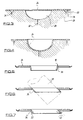
- a sheet (24) of synthetic plastics material such as P.V.C. is vacuum formed in suitable mould (26) having a main cavity (28) and a bead cavity (30) surrounding the main cavity.
- Sheet (24) is placed over the mould and suitably heated, and then the cavities (28) and (30) have vacuum applied thereto through for example pipes (32) and (34) so that the plastics material sheet is deformed as shown in Fig. 4 to take up the shape of the mould.
- the moulding thus formed is then severed through the central deformed portion to provide the collar (18) as shown in Fig. 5, and the collar (18) is provided with a central flange (36) which is configured at an angle by means of a hot forming tube (38) as illustrated in Fig. 6, the said angle being the same as the angle at which the lateral pipe (12) meets the main pipe (10).
- heated shaper (40) is applied to the rim of the flange (36) to form the outwardly turned bead formation (22) as previously described in relation to Fig. 2, completing the manufacture of the sealing collar.
- the sealing collar (18) is shown, after having been inverted from its Fig. 7 position, and the lining tube (14) with its collar (16) is inserted again under factory conditions, through the central aperture of the collar (18), until the collar (16) seats on collar (18).
- the collar (16) although of the same material as the lining tube (14) is not in fact impregnated with resin at this time, but it is bonded to the upper surface of collar (18) by a suitable adhesive or cement and again this fabrication takes place under factory conditions.
- the “launcher” comprises basically a tubular body (42) supporting a front arm (44) via a bracket (46), and a saddle bracket (48).
- a mounting cap (50) which is a tubular structure through which the lining and the carrier tube (to be described) pass in order to effect the eversion of the lining tube into the lateral pipe (14).
- the cap (50) is inter changeable with caps of different sizes depending upon the diameter of the lateral pipe to be lined, and it will be appreciated that the lining tube is tailored under factory conditions to be the correct size to line the lateral pipeline (14).
- Fig. 10 shows the "launcher" when in position in the main pipe (10) and when in register with the lateral pipe (12) ready to evert the lining tube (14) into the lateral pipe (12), and referring to that figure, the body (42) is shown as being connected to a tail pipe (52) which is flexible, and serves as a containment means for pressurising gas e.g. compressed air, which is introduced into the interior of the body (42) by means of a compressed air line (54), in order to pressurise a chamber comprising the inside of the body (42) containment tube (52) and the cap (50).
- pressurising gas e.g. compressed air
- a carrier tube (56) which is of flexible resilient material such as a rubberised fabric, has an end (58) folded over the outside of the cap (50), and the remainder of the carrier tube passes through the pressurising chamber.
- the main body of the lining tube (14) is carried inside the carrier tube, but the flanged end (16) projects therefrom and presses on the collar (18).
- the collar (18) is in turn supported on the arm (44) and bracket (48) so as to be presented to the lateral lining pipe (12) as shown in Fig. 10.
- the lining tube includes a curable resin impregnated fibrous or felt layer
- the lining is held in this position by the carrier tube until the resin cures, when the carrier tube is removed leaving the lining in position as shown in Fig. 2.
- Fig. 11 shows an alternative design for the collar 18.
- the collar of Fig. 11 is again thermoformed from plastics material, but is generally rectangular in shape, but in being thermoformed is curved in the main body region 60 to the curvature of the pipe.
- formations 62 and 64 which are adapted to be engaged by the launcher (44 and 48).
- the central aperture 64 In the centre of the body portion 60 is provided the central aperture 64 through which the lining will be everted.
- apertures 68 and 70 are provided in the upstanding flange 72 surrounding the aperture 64. These apertures 68 and 70 may be used for fixing devices in order to enhance the fixing of the lining collar to the thermoformed collar as shown in Fig. 11.
- the Fig. 11 collar differs from the Fig. 8 collar insofar as the body portion 60 is pre-curved to the curvature of the pipe whereas in the arrangement of Fig. 8 the body portion is flat and will be stressed to the curvature of the pipe as it is pressed thereto.
- the arrangement shown is for a lateral pipe which meets the main pipe at an angle for example in the order of 45 degrees.
- the system can be adapted for the lining of laterals which meet the pipeline at different angles, and for laterals which are of different sizes.
- a single "launcher” may be used for all sizes of lateral pipes which meet a main pipe at the same angle, and also “launchers” can be designed for other angles such as 60 degrees or even 90 degrees.
Landscapes
- Engineering & Computer Science (AREA)
- General Engineering & Computer Science (AREA)
- Mechanical Engineering (AREA)
- Lining Or Joining Of Plastics Or The Like (AREA)
- Pipe Accessories (AREA)
- Application Of Or Painting With Fluid Materials (AREA)
- Supports For Pipes And Cables (AREA)
- Rigid Pipes And Flexible Pipes (AREA)
- Sewage (AREA)
Abstract
Description
Claims (10)
- A tubular lining for lining a lateral pipe (12) branching off from a main pipe (10), wherein a lining tube(14) is provided with a substantially tubular lining portion (14) having a sealing end (16, 18) adapted to conform and seal to the inner face of the pipe in the region where the lateral pipe(12) is connected to the main pipe (10), and wherein said end (16, 18) includes a sealing collar (18) comprising a body (24, 60) having an aperture (64), a rim (36) surrounding said aperture on one side of the body (24, 60), arranged so that when applying the lining to the lateral pipe (12) from the main pipe (10), the rim (36) can be located in the lateral pipe and the sealing collar seals the region where the lateral pipe (12) meets the main pipe (10), characterised in that the lining tube (14) is provided with a resin absorbent layer capable of being impregnated with a curable resin and the sealing end includes the resin absorbent layer (16) arranged to extend along the inner surface of the main pipe (10) in the region of the lateral pipe (12) for improving the seal.
- A lining according to claim 1, characterised in that said sealing collar (18) is thermoformed from a sheet of synthetic plastics material, such as polyvinyl chloride.
- A lining according to claims 1 or 2, characterised in that the rim (36) forms a cylinder whose longitudinal axis is inclined in relation to the body of the collar (18) at the same angle at which the lateral (12) is inclined relative to the main pipe (10).
- A lining according to any of claims 1-3, characterised in that the lining tube (14) is contained within a carrier tube (56).
- A lining according to any preceding claim, characterised in that the rim top is outwardly turned so as to provide a lip (22) which serves as a means for gripping the resin absorbent material (16) arranged to extend along the main pipe (10).
- A lining according to any preceding claim, characterised in that the resin absorbent material (16) arranged to extend along the main pipe (10) is adhered to the sealing collar (18) by means of a suitable adhesive or other bonding material.
- A method for lining a lateral pipe (12) branching off from a main pipe (10) by means of a lining tube provided with a substantially tubular lining portion (14) having a sealing end (16, 18)which includes a sealing collar (18) comprising a body (24, 60) having an aperture (64) and a rim (36) surrounding said aperture on one side of the body (24, 60) characterised by the steps of providing that the tubular lining portion (14) extends through the aperture to the sealing end (16, 18) so that the scaling end of the lining tube becomes the leading end, pressing the sealing collar (18) from inside the main pipe (10) to the region where the lateral pipe (12) meets the main pipe (10) so that the rim (36) locates in the lateral pipe (12), and the sealing end (16, 18) conforms and seals to the inner face of the main pipe (10) and everting the lining portion (14) through the collar (18) onto the lateral pipe surface.
- A method according to claim 7, characterised in that a launching device presses the sealing collar (18) to the main pipe (10).
- A method according to claim 7 or 8, characterised in that the lining portion (14) is everted by means of fluid pressure.
- A method according to any of claims 7-9, characterised in that the lining portion (14) is impregnated by a curable resin and in that the lining portion (14) is held in position on the surface of the lateral (12) until the curable resin is cured, so s to form a rigid lining on said lateral surface.
Applications Claiming Priority (3)
| Application Number | Priority Date | Filing Date | Title |
|---|---|---|---|
| GB9225528 | 1992-12-07 | ||
| GB929225528A GB9225528D0 (en) | 1992-12-07 | 1992-12-07 | Improvements relating to the lining of pipelines and passageways |
| PCT/GB1993/001838 WO1994013998A1 (en) | 1992-12-07 | 1993-09-09 | Improvements relating to the lining of pipelines and passageways |
Publications (2)
| Publication Number | Publication Date |
|---|---|
| EP0672229A1 EP0672229A1 (en) | 1995-09-20 |
| EP0672229B1 true EP0672229B1 (en) | 1998-05-06 |
Family
ID=10726236
Family Applications (1)
| Application Number | Title | Priority Date | Filing Date |
|---|---|---|---|
| EP94918230A Expired - Lifetime EP0672229B1 (en) | 1992-12-07 | 1993-09-09 | Lining tube for laterals and method of lining laterals |
Country Status (14)
| Country | Link |
|---|---|
| US (1) | US5692543A (en) |
| EP (1) | EP0672229B1 (en) |
| JP (1) | JPH08504253A (en) |
| CN (1) | CN1089710A (en) |
| AT (1) | ATE165905T1 (en) |
| AU (1) | AU677229B2 (en) |
| CA (1) | CA2150111A1 (en) |
| DE (1) | DE69318419T2 (en) |
| DK (1) | DK0672229T3 (en) |
| FI (1) | FI952810A7 (en) |
| GB (1) | GB9225528D0 (en) |
| NO (1) | NO952167L (en) |
| TW (1) | TW247924B (en) |
| WO (1) | WO1994013998A1 (en) |
Families Citing this family (44)
| Publication number | Priority date | Publication date | Assignee | Title |
|---|---|---|---|---|
| US6337114B1 (en) * | 1992-09-10 | 2002-01-08 | Insituform (Netherlands) B.V. | Flexible lining with flexible collar for lining lateral pipelines |
| GB9319832D0 (en) * | 1993-09-25 | 1993-11-10 | Insituform Technologies Inc | Improvements relating to the lining of pipelines and passageways |
| US5950682A (en) * | 1994-08-19 | 1999-09-14 | Lmk Enterprises, Inc. | Apparatus and method for repairing the junction of a sewer main line and lateral |
| AT402550B (en) * | 1995-04-07 | 1997-06-25 | Kuebel Johann | METHOD AND DEVICE FOR REFURBISHING THE LEAKING WALLS OF PIPES |
| US5916406A (en) * | 1996-02-14 | 1999-06-29 | Shonan Gosei-Jushi Seisakusho Kk | Branch pipe liner bag and pipe lining method |
| US5816293A (en) * | 1996-03-27 | 1998-10-06 | Kiest, Jr.; Larry W. | Apparatus for installation of a liner within a pipeline |
| JPH10278115A (en) * | 1997-02-04 | 1998-10-20 | Shonan Gosei Jushi Seisakusho:Kk | Branch pipe lining material and pipe lining technique |
| US5944058A (en) * | 1997-02-04 | 1999-08-31 | Shonan Gosei-Jushi Seisakusho K.K. | Branch pipe liner assembly and a pipe lining method |
| DE19718655C2 (en) * | 1997-05-02 | 1999-06-10 | Braun Karl Otto Kg | Tubular lining material, pipe lining made therefrom and method for making the same |
| TW386936B (en) * | 1997-07-18 | 2000-04-11 | Get Inc | Making jig for a branch opening and pipe lining working method for a branch opening |
| JPH11105136A (en) * | 1997-10-06 | 1999-04-20 | Shonan Gosei Jushi Seisakusho:Kk | Branch pipe lining material and pipe lining method |
| US6068725A (en) * | 1997-11-26 | 2000-05-30 | Insituform (Netherlands) B.V. | Method of installation of a flexible cured in place lateral seal in an existing main pipeline |
| US6029726A (en) | 1997-11-26 | 2000-02-29 | Insituform (Netherlands) B.V. | Apparatus for installing a flexible cured in place lateral seal in an existing main pipeline |
| US5915419A (en) * | 1997-11-26 | 1999-06-29 | Insituform (Netherlands) B.V. | Cured in place lateral seal for relining of pipelines and method of manufacture |
| JPH11207821A (en) * | 1998-01-27 | 1999-08-03 | Shonan Gosei Jushi Seisakusho:Kk | Pipe lining method |
| JPH11227049A (en) * | 1998-02-12 | 1999-08-24 | Shonan Gosei Jushi Seisakusho:Kk | Branch pipe lining material and branch pipe lining method |
| US6039079A (en) * | 1998-07-17 | 2000-03-21 | Lmk Enterprises, Inc. | Apparatus and method for repairing the junction of a sewer main line and lateral pipe |
| JP2000052426A (en) * | 1998-08-06 | 2000-02-22 | Shonan Gosei Jushi Seisakusho:Kk | Branch pipe lining material and pipe lining method |
| US6206049B1 (en) * | 1998-11-20 | 2001-03-27 | Tele Environmental Systems | Apparatus and method for the robotic repairing of an underground pipe junction with removable heating element |
| US6082411A (en) * | 1998-11-20 | 2000-07-04 | Tele Environmental Systems | Apparatus and method for the robotic repairing of an underground pipe junction |
| US6253846B1 (en) * | 1999-02-24 | 2001-07-03 | Shell Oil Company | Internal junction reinforcement and method of use |
| US6691741B2 (en) * | 2001-10-05 | 2004-02-17 | Nuflow Technologies (2000) Inc. | Installation assemblies for pipeline liners, pipeline liners and methods for installing the same |
| US6688337B2 (en) | 2001-12-19 | 2004-02-10 | Robert M. Ward | Apparatus and method for the robotic repairing of an underground pipe junction with a flexible patch mechanism |
| US20040020544A1 (en) * | 2002-04-05 | 2004-02-05 | Takao Kamiyama | Pressure bag and method of lining branch pipe |
| US6732763B2 (en) | 2002-05-24 | 2004-05-11 | Lantor, Inc. | Stretch-resistant pipe liner |
| DE10311828A1 (en) * | 2003-03-14 | 2004-09-23 | Helmar Haas | Device for renovating house connection lines from a ground line |
| US7849883B2 (en) * | 2005-05-02 | 2010-12-14 | Nuflow Technologies 2000 Inc. | Liner assembly for pipeline repair and methods of installing same |
| MX2008013790A (en) * | 2006-04-27 | 2009-01-09 | Ina Acquisition Corp | Reinstatement of an existing connection in a lined conduit. |
| US7845372B2 (en) * | 2007-03-30 | 2010-12-07 | Lmk Enterprises, Inc. | Bladderless pipeliner and method for using same |
| US20090194183A1 (en) * | 2008-02-05 | 2009-08-06 | Lmk Enterprises, Inc. | Bladder and method for cured-in-place pipe lining |
| US7987873B2 (en) * | 2008-02-06 | 2011-08-02 | Lmk Enterprises, Inc. | Device and method for repairing pipe |
| US20090289451A1 (en) * | 2008-05-21 | 2009-11-26 | Ina Acquisition Corp. | T-Nut Assembly For Sealing An Existing Connection In A Lined Conduit |
| ES2399488T3 (en) * | 2009-03-09 | 2013-04-01 | Georg Fischer Jrg Ag | Procedure for the manufacture of a hollow body with a tubular shape, as well as a hollow body with a tubular shape |
| JP5534585B2 (en) * | 2010-01-29 | 2014-07-02 | 株式会社湘南合成樹脂製作所 | Branch pipe lining manufacturing method |
| US8820363B2 (en) * | 2010-03-24 | 2014-09-02 | Ina Acquisition Corp. | Wedge type plug and method of plugging a lateral line |
| CN107101426B (en) * | 2016-02-19 | 2020-11-13 | 浙江三花智能控制股份有限公司 | Filling tube for filter drier, refrigerator and method for producing the filling tube |
| US10767805B2 (en) * | 2016-07-28 | 2020-09-08 | BLD Services, LLC | Pipe lining systems and methods of use |
| CN106838477A (en) * | 2017-02-21 | 2017-06-13 | 东莞市利发爱尔空气净化系统有限公司 | A kind of sealing device for Pipe installing |
| GB201804435D0 (en) * | 2018-03-20 | 2018-05-02 | Corfitz Solutions Ltd | Improvements relating to devices |
| MX2021006655A (en) * | 2018-12-07 | 2021-07-07 | Team Ind Services Inc | Auto extruded split/spherical tee and full encirclement saddle. |
| CN112780877B (en) * | 2021-01-20 | 2023-04-25 | 中国石油天然气集团有限公司 | B-type sleeve for repairing girth weld defects between three-way branch pipe and butt-joint steel pipe and mounting method thereof |
| CN113175051B (en) * | 2021-03-24 | 2023-12-22 | 嘉兴倍创网络科技有限公司 | A high-efficiency self-cleaning sewer pipe |
| US11643801B1 (en) * | 2021-12-29 | 2023-05-09 | Gulf Coast Underground, LLC | System and method for sealing an annular space of a sewer connection line |
| KR102860133B1 (en) | 2022-06-09 | 2025-09-15 | 가부시키가이샤 쇼난 고세이쥬시 세이사쿠쇼 | Branch pipe liner and manufacturing method thereof |
Family Cites Families (16)
| Publication number | Priority date | Publication date | Assignee | Title |
|---|---|---|---|---|
| GB2041147B (en) * | 1979-01-22 | 1982-12-15 | Fusion Equipment Ltd | Renovating sewers |
| GB2091611B (en) | 1981-01-24 | 1984-06-20 | Insituform Int Inc | Cutting of side connections in pipes |
| GB2092493B (en) | 1981-02-06 | 1983-11-16 | Insituform Int Inc | A method of cutting side connectors in the lining of an underground pipe |
| GB2096265B (en) | 1981-02-18 | 1984-08-01 | Insituform Pipes & Structures | Lining of side connections |
| GB8407706D0 (en) | 1984-03-24 | 1984-05-02 | Edgealpha Ltd | Lining pipelines in passageways |
| GB8429339D0 (en) | 1984-11-21 | 1985-01-03 | Edgealpha Ltd | Pipeline inspection apparatus |
| GB8527700D0 (en) | 1985-11-09 | 1985-12-11 | Edgealpha Ltd | Curing of lateral linings |
| GB8609307D0 (en) | 1986-04-16 | 1986-05-21 | Insituform Group Ltd | Lining of piplines |
| DE3929558A1 (en) * | 1989-09-06 | 1991-03-07 | Hans Mueller | Sealing joint between mains drain and house connection - involves resin-impregnated insert, placed into house pipe without excavation of ground |
| EP0502072B1 (en) * | 1989-11-21 | 1993-09-01 | Wavin B.V. | Thermoplastic saddle in two parts for repairing or renovating a pipeline with branch pipe and repaired or renovated pipe with a saddle |
| US4991006A (en) | 1990-03-08 | 1991-02-05 | Insituform Licensees, B. V. | Apparatus using an everted hose for inspecting the interior of a lateral pipeline |
| GB9009073D0 (en) * | 1990-04-23 | 1990-06-20 | Insituform Group Ltd | Improvements relating to the lining of pipelines or passageways |
| US5044824A (en) | 1990-05-01 | 1991-09-03 | Long Technologies, Inc. | Method and apparatus for locating a service pipe outlet transversely connected to a lined main pipe |
| DE4031949C2 (en) * | 1990-10-09 | 1994-12-01 | Bauunternehmung Bergfort Gmbh | Method and device for the rehabilitation of sewers |
| JP2554411B2 (en) * | 1991-05-31 | 1996-11-13 | 株式会社ゲット | Branch pipe lining material and manufacturing method thereof |
| GB9127315D0 (en) | 1991-12-23 | 1992-02-19 | Insituform Group Ltd | Improvements relating to the lining of pipelines and passageways |
-
1992
- 1992-12-07 GB GB929225528A patent/GB9225528D0/en active Pending
-
1993
- 1993-09-09 CA CA002150111A patent/CA2150111A1/en not_active Abandoned
- 1993-09-09 AT AT94918230T patent/ATE165905T1/en not_active IP Right Cessation
- 1993-09-09 EP EP94918230A patent/EP0672229B1/en not_active Expired - Lifetime
- 1993-09-09 US US08/454,373 patent/US5692543A/en not_active Expired - Lifetime
- 1993-09-09 WO PCT/GB1993/001838 patent/WO1994013998A1/en not_active Ceased
- 1993-09-09 AU AU49722/93A patent/AU677229B2/en not_active Ceased
- 1993-09-09 DE DE69318419T patent/DE69318419T2/en not_active Expired - Fee Related
- 1993-09-09 DK DK94918230T patent/DK0672229T3/en active
- 1993-09-09 FI FI952810A patent/FI952810A7/en not_active Application Discontinuation
- 1993-09-09 JP JP6513900A patent/JPH08504253A/en active Pending
- 1993-11-30 TW TW082110124A patent/TW247924B/zh active
- 1993-12-03 CN CN93120095.4A patent/CN1089710A/en active Pending
-
1995
- 1995-06-01 NO NO952167A patent/NO952167L/en unknown
Also Published As
| Publication number | Publication date |
|---|---|
| NO952167L (en) | 1995-06-07 |
| CA2150111A1 (en) | 1994-06-23 |
| FI952810A0 (en) | 1995-06-07 |
| EP0672229A1 (en) | 1995-09-20 |
| DE69318419T2 (en) | 1998-09-03 |
| WO1994013998A1 (en) | 1994-06-23 |
| NO952167D0 (en) | 1995-06-01 |
| CN1089710A (en) | 1994-07-20 |
| TW247924B (en) | 1995-05-21 |
| ATE165905T1 (en) | 1998-05-15 |
| AU4972293A (en) | 1994-07-04 |
| JPH08504253A (en) | 1996-05-07 |
| US5692543A (en) | 1997-12-02 |
| FI952810L (en) | 1995-06-07 |
| GB9225528D0 (en) | 1993-01-27 |
| DE69318419D1 (en) | 1998-06-10 |
| DK0672229T3 (en) | 1998-10-07 |
| AU677229B2 (en) | 1997-04-17 |
| FI952810A7 (en) | 1995-06-07 |
Similar Documents
| Publication | Publication Date | Title |
|---|---|---|
| EP0672229B1 (en) | Lining tube for laterals and method of lining laterals | |
| US5927341A (en) | Lining of "Tees" and "Wyes" in pipelines or passageways | |
| US5950682A (en) | Apparatus and method for repairing the junction of a sewer main line and lateral | |
| US5706861A (en) | Rehabilitation of pipelines and passageways with a flexible liner using an inflatible bladder | |
| US5971029A (en) | Dual containment pipe system and method of installation | |
| EP2185854B1 (en) | Method for repairing pipe | |
| US5964249A (en) | Apparatus and method for repairing a pipeline | |
| US6001212A (en) | Method for lining of lateral pipelines with flow-through apparatus | |
| US8550121B2 (en) | Method and apparatus for lining a pipe | |
| US5736166A (en) | Flow-through apparatus for lining of pipelines | |
| US8240340B2 (en) | Hydrophilic end seal | |
| EP3092434B1 (en) | Method and apparatus for lining a pipe | |
| WO2019079370A1 (en) | Method and apparatus for repairing a length of pipe or a main/lateral pipe junction | |
| EP1426671B1 (en) | Method for using a lateral liner and main liner to repair pipeline | |
| JP2004148512A (en) | Pipe lining method | |
| JP2004148515A (en) | Pipe lining method | |
| AU2011244936B2 (en) | Device and method for repairing pipe | |
| JPH1034750A (en) | Lining material for duct | |
| WO2020072658A1 (en) | Method and assembly for sealing off a pipe | |
| JPH1080951A (en) | Cylindrical lining material with flange |
Legal Events
| Date | Code | Title | Description |
|---|---|---|---|
| PUAI | Public reference made under article 153(3) epc to a published international application that has entered the european phase |
Free format text: ORIGINAL CODE: 0009012 |
|
| 17P | Request for examination filed |
Effective date: 19950518 |
|
| AK | Designated contracting states |
Kind code of ref document: A1 Designated state(s): AT BE CH DE DK ES FR GB GR IE IT LI LU MC NL PT SE |
|
| 17Q | First examination report despatched |
Effective date: 19970211 |
|
| GRAG | Despatch of communication of intention to grant |
Free format text: ORIGINAL CODE: EPIDOS AGRA |
|
| GRAG | Despatch of communication of intention to grant |
Free format text: ORIGINAL CODE: EPIDOS AGRA |
|
| GRAH | Despatch of communication of intention to grant a patent |
Free format text: ORIGINAL CODE: EPIDOS IGRA |
|
| GRAH | Despatch of communication of intention to grant a patent |
Free format text: ORIGINAL CODE: EPIDOS IGRA |
|
| RAP1 | Party data changed (applicant data changed or rights of an application transferred) |
Owner name: INSITUFORM LICENCEES BV/SA Owner name: INSITUFORM HOLDINGS (UK) LTD Owner name: INA ACQUISITION CORPORATION |
|
| RAP1 | Party data changed (applicant data changed or rights of an application transferred) |
Owner name: INSITUFORM LICENCEES BV/SA Owner name: INSITUFORM HOLDINGS (UK) LTD Owner name: INA ACQUISITION CORPORATION |
|
| GRAA | (expected) grant |
Free format text: ORIGINAL CODE: 0009210 |
|
| RAP1 | Party data changed (applicant data changed or rights of an application transferred) |
Owner name: INSITUFORM LICENCEES BV/SA Owner name: INSITUFORM HOLDINGS (UK) LTD Owner name: INA ACQUISITION CORPORATION |
|
| AK | Designated contracting states |
Kind code of ref document: B1 Designated state(s): AT BE CH DE DK ES FR GB GR IE IT LI LU MC NL PT SE |
|
| PG25 | Lapsed in a contracting state [announced via postgrant information from national office to epo] |
Ref country code: LI Free format text: LAPSE BECAUSE OF FAILURE TO SUBMIT A TRANSLATION OF THE DESCRIPTION OR TO PAY THE FEE WITHIN THE PRESCRIBED TIME-LIMIT Effective date: 19980506 Ref country code: IT Free format text: LAPSE BECAUSE OF FAILURE TO SUBMIT A TRANSLATION OF THE DESCRIPTION OR TO PAY THE FEE WITHIN THE PRE;WARNING: LAPSES OF ITALIAN PATENTS WITH EFFECTIVE DATE BEFORE 2007 MAY HAVE OCCURRED AT ANY TIME BEFORE 2007. THE CORRECT EFFECTIVE DATE MAY BE DIFFERENT FROM THE ONE RECORDED.SCRIBED TIME-LIMIT Effective date: 19980506 Ref country code: GR Free format text: LAPSE BECAUSE OF FAILURE TO SUBMIT A TRANSLATION OF THE DESCRIPTION OR TO PAY THE FEE WITHIN THE PRESCRIBED TIME-LIMIT Effective date: 19980506 Ref country code: ES Free format text: THE PATENT HAS BEEN ANNULLED BY A DECISION OF A NATIONAL AUTHORITY Effective date: 19980506 Ref country code: CH Free format text: LAPSE BECAUSE OF FAILURE TO SUBMIT A TRANSLATION OF THE DESCRIPTION OR TO PAY THE FEE WITHIN THE PRESCRIBED TIME-LIMIT Effective date: 19980506 Ref country code: AT Free format text: LAPSE BECAUSE OF FAILURE TO SUBMIT A TRANSLATION OF THE DESCRIPTION OR TO PAY THE FEE WITHIN THE PRESCRIBED TIME-LIMIT Effective date: 19980506 |
|
| REF | Corresponds to: |
Ref document number: 165905 Country of ref document: AT Date of ref document: 19980515 Kind code of ref document: T |
|
| ET | Fr: translation filed | ||
| REG | Reference to a national code |
Ref country code: CH Ref legal event code: EP |
|
| REF | Corresponds to: |
Ref document number: 69318419 Country of ref document: DE Date of ref document: 19980610 |
|
| PG25 | Lapsed in a contracting state [announced via postgrant information from national office to epo] |
Ref country code: SE Free format text: LAPSE BECAUSE OF FAILURE TO SUBMIT A TRANSLATION OF THE DESCRIPTION OR TO PAY THE FEE WITHIN THE PRESCRIBED TIME-LIMIT Effective date: 19980806 Ref country code: PT Free format text: LAPSE BECAUSE OF FAILURE TO SUBMIT A TRANSLATION OF THE DESCRIPTION OR TO PAY THE FEE WITHIN THE PRESCRIBED TIME-LIMIT Effective date: 19980806 |
|
| REG | Reference to a national code |
Ref country code: IE Ref legal event code: FG4D Free format text: 80202 |
|
| PGFP | Annual fee paid to national office [announced via postgrant information from national office to epo] |
Ref country code: GB Payment date: 19980902 Year of fee payment: 6 |
|
| PG25 | Lapsed in a contracting state [announced via postgrant information from national office to epo] |
Ref country code: LU Free format text: LAPSE BECAUSE OF NON-PAYMENT OF DUE FEES Effective date: 19980909 Ref country code: IE Free format text: LAPSE BECAUSE OF NON-PAYMENT OF DUE FEES Effective date: 19980909 |
|
| PGFP | Annual fee paid to national office [announced via postgrant information from national office to epo] |
Ref country code: FR Payment date: 19980909 Year of fee payment: 6 |
|
| PGFP | Annual fee paid to national office [announced via postgrant information from national office to epo] |
Ref country code: DK Payment date: 19980914 Year of fee payment: 6 |
|
| PGFP | Annual fee paid to national office [announced via postgrant information from national office to epo] |
Ref country code: DE Payment date: 19980921 Year of fee payment: 6 |
|
| PGFP | Annual fee paid to national office [announced via postgrant information from national office to epo] |
Ref country code: NL Payment date: 19980929 Year of fee payment: 6 |
|
| REG | Reference to a national code |
Ref country code: DK Ref legal event code: T3 |
|
| REG | Reference to a national code |
Ref country code: CH Ref legal event code: PL |
|
| PGFP | Annual fee paid to national office [announced via postgrant information from national office to epo] |
Ref country code: BE Payment date: 19981118 Year of fee payment: 6 |
|
| PLBE | No opposition filed within time limit |
Free format text: ORIGINAL CODE: 0009261 |
|
| STAA | Information on the status of an ep patent application or granted ep patent |
Free format text: STATUS: NO OPPOSITION FILED WITHIN TIME LIMIT |
|
| PG25 | Lapsed in a contracting state [announced via postgrant information from national office to epo] |
Ref country code: MC Free format text: LAPSE BECAUSE OF NON-PAYMENT OF DUE FEES Effective date: 19990331 |
|
| 26N | No opposition filed | ||
| PG25 | Lapsed in a contracting state [announced via postgrant information from national office to epo] |
Ref country code: GB Free format text: LAPSE BECAUSE OF NON-PAYMENT OF DUE FEES Effective date: 19990909 Ref country code: DK Free format text: LAPSE BECAUSE OF NON-PAYMENT OF DUE FEES Effective date: 19990909 |
|
| PG25 | Lapsed in a contracting state [announced via postgrant information from national office to epo] |
Ref country code: BE Free format text: LAPSE BECAUSE OF NON-PAYMENT OF DUE FEES Effective date: 19990930 |
|
| BERE | Be: lapsed |
Owner name: INA ACQUISITION CORP. Effective date: 19990930 |
|
| PG25 | Lapsed in a contracting state [announced via postgrant information from national office to epo] |
Ref country code: NL Free format text: LAPSE BECAUSE OF NON-PAYMENT OF DUE FEES Effective date: 20000401 |
|
| GBPC | Gb: european patent ceased through non-payment of renewal fee |
Effective date: 19990909 |
|
| PG25 | Lapsed in a contracting state [announced via postgrant information from national office to epo] |
Ref country code: FR Free format text: LAPSE BECAUSE OF NON-PAYMENT OF DUE FEES Effective date: 20000531 |
|
| NLV4 | Nl: lapsed or anulled due to non-payment of the annual fee |
Effective date: 20000401 |
|
| PG25 | Lapsed in a contracting state [announced via postgrant information from national office to epo] |
Ref country code: DE Free format text: LAPSE BECAUSE OF NON-PAYMENT OF DUE FEES Effective date: 20000701 |
|
| REG | Reference to a national code |
Ref country code: FR Ref legal event code: ST |
|
| REG | Reference to a national code |
Ref country code: DK Ref legal event code: EBP |