EP0674322A1 - Assemblage combustible pour réacteur nucléaire et méthode de fabrication - Google Patents
Assemblage combustible pour réacteur nucléaire et méthode de fabrication Download PDFInfo
- Publication number
- EP0674322A1 EP0674322A1 EP95103966A EP95103966A EP0674322A1 EP 0674322 A1 EP0674322 A1 EP 0674322A1 EP 95103966 A EP95103966 A EP 95103966A EP 95103966 A EP95103966 A EP 95103966A EP 0674322 A1 EP0674322 A1 EP 0674322A1
- Authority
- EP
- European Patent Office
- Prior art keywords
- fuel assembly
- alloy
- fuel
- containing metal
- assembly element
- Prior art date
- Legal status (The legal status is an assumption and is not a legal conclusion. Google has not performed a legal analysis and makes no representation as to the accuracy of the status listed.)
- Granted
Links
Images


Classifications
-
- G—PHYSICS
- G21—NUCLEAR PHYSICS; NUCLEAR ENGINEERING
- G21C—NUCLEAR REACTORS
- G21C3/00—Reactor fuel elements and their assemblies; Selection of substances for use as reactor fuel elements
- G21C3/42—Selection of substances for use as reactor fuel
- G21C3/58—Solid reactor fuel Pellets made of fissile material
- G21C3/60—Metallic fuel; Intermetallic dispersions
-
- C—CHEMISTRY; METALLURGY
- C22—METALLURGY; FERROUS OR NON-FERROUS ALLOYS; TREATMENT OF ALLOYS OR NON-FERROUS METALS
- C22C—ALLOYS
- C22C1/00—Making non-ferrous alloys
- C22C1/04—Making non-ferrous alloys by powder metallurgy
- C22C1/047—Making non-ferrous alloys by powder metallurgy comprising intermetallic compounds
-
- C—CHEMISTRY; METALLURGY
- C22—METALLURGY; FERROUS OR NON-FERROUS ALLOYS; TREATMENT OF ALLOYS OR NON-FERROUS METALS
- C22C—ALLOYS
- C22C16/00—Alloys based on zirconium
-
- B—PERFORMING OPERATIONS; TRANSPORTING
- B22—CASTING; POWDER METALLURGY
- B22F—WORKING METALLIC POWDER; MANUFACTURE OF ARTICLES FROM METALLIC POWDER; MAKING METALLIC POWDER; APPARATUS OR DEVICES SPECIALLY ADAPTED FOR METALLIC POWDER
- B22F2998/00—Supplementary information concerning processes or compositions relating to powder metallurgy
- B22F2998/10—Processes characterised by the sequence of their steps
-
- Y—GENERAL TAGGING OF NEW TECHNOLOGICAL DEVELOPMENTS; GENERAL TAGGING OF CROSS-SECTIONAL TECHNOLOGIES SPANNING OVER SEVERAL SECTIONS OF THE IPC; TECHNICAL SUBJECTS COVERED BY FORMER USPC CROSS-REFERENCE ART COLLECTIONS [XRACs] AND DIGESTS
- Y02—TECHNOLOGIES OR APPLICATIONS FOR MITIGATION OR ADAPTATION AGAINST CLIMATE CHANGE
- Y02E—REDUCTION OF GREENHOUSE GAS [GHG] EMISSIONS, RELATED TO ENERGY GENERATION, TRANSMISSION OR DISTRIBUTION
- Y02E30/00—Energy generation of nuclear origin
- Y02E30/30—Nuclear fission reactors
-
- Y—GENERAL TAGGING OF NEW TECHNOLOGICAL DEVELOPMENTS; GENERAL TAGGING OF CROSS-SECTIONAL TECHNOLOGIES SPANNING OVER SEVERAL SECTIONS OF THE IPC; TECHNICAL SUBJECTS COVERED BY FORMER USPC CROSS-REFERENCE ART COLLECTIONS [XRACs] AND DIGESTS
- Y10—TECHNICAL SUBJECTS COVERED BY FORMER USPC
- Y10S—TECHNICAL SUBJECTS COVERED BY FORMER USPC CROSS-REFERENCE ART COLLECTIONS [XRACs] AND DIGESTS
- Y10S376/00—Induced nuclear reactions: processes, systems, and elements
- Y10S376/90—Particular material or material shapes for fission reactors
Definitions
- the present invention relates to a method of manufacturing a fuel assembly applicable for a core of a nuclear reactor using a fuel containing Pu239, members constituting the fuel assembly (sometimes referred to herein as "fuel assembly elements"), and alloys used for the members.
- the present invention concerns a method of manufacturing a fuel assembly applicable for a reactor core in which a water-uranium fuel volume ratio is 1.5 or less and the conversion ratio from U238 to Pu239 is high, members constituting the fuel assembly, and alloys used for the members.
- a high conversion reactor acts as a bridge between a light water reactor and a fast breeder reactor, and has a feature of effectively converting non-fissionable U238 contained in natural uranium to fissionable Pu239 usable for power generation.
- the non-fissionable U238, which has been not used in a light water reactor, can be used by the high conversion reactor, resulting in the effective utilization of uranium resource.
- the stored Pu239 can be effectively utilized as a fuel for a fast breeder reactor, or a fuel for a high conversion reactor and a general breeder reactor.
- the reduction in the exhaust amount of a spent fuel by increasing an operation cycle and the burn-up of fuel contributes to an economic merit, for example in reducing a power generation cost.
- the operation cycle is increased and the burn-up of fuel is enhanced, the staying period of a fuel assembly in a reactor is increased. This further accelerates the corrosion of the surfaces of members constituting the fuel assembly in water at a high temperature/high pressure.
- the effective conversion from U238 to fissionable Pu239 is mainly due to resonance neutrons having an energy higher than that of thermal neutrons.
- neutron spectrum in a reactor core is hardened (a large number of neutrons having high energy exist), thus accelerating the damage of the material due to neutrons.
- zirconium alloy (normally used as a high corrosion resisting alloy) has a tendency to become brittle by fast neutron irradiation.
- a member constituting a ZIRCALOY fuel assembly generates a local oxidization called the nodular corrosion, and the corrosion portion propagates with time.
- a method of reducing this corrosion has been known, wherein a heat-treatment of heating a zirconium alloy for a short period of time in a temperature range of ( ⁇ + ⁇ ) phase or ⁇ phase and quenching the alloy is inserted in the downstream step in a member manufacturing process (for example, Unexamined Japanese Patent Publications Nos. SHO 51-110411 and SHO 51-110412, and Examined Japanese Patent Publications Nos. SHO 60-59983 and SHO 63-31543).
- This known technique is called ( ⁇ + ⁇ ) quenching or ⁇ quenching, which is applied to alloys used for the existing light water reactor: ZIRCALOY-2 (Sn: 1.2-1.7 wt%, Fe: 0.10-1.20 wt%, Cr: 0.05-0.15 wt%, Ni: 0.03-0.08 wt%, O: 0.06-0.14 wt%, and the balance: Zr); and ZIRCALOY-4 (Sn: 1.2-1.7 wt%, Fe: 0.15-1.24 wt%, Cr: 0.05-0.15 wt%, O: 0.06-0.14 wt%, and the balance: Zr).
- Fe, Cr and Ni are elements for improving corrosion resistance
- Sn is an element of improving strength
- Fe, Cr, Ni precipitate as intermetallic compounds within crystal grains and crystal boundaries. These intermetallic compounds are refined by the ( ⁇ + ⁇ ) quenching or ⁇ quenching; and further when the cooling rate is sufficiently large, they are dissolved in solid even in the matrix.
- the mechanism of enhancing the corrosion resistance is not fully understood, but it is generally considered that the refining of precipitations and the increase in the concentration of solid-solution of Fe, Ni, and Cr contribute to the increase in the corrosion resistance.
- alloy composition and alloy components leads to the enhancement of the corrosion resistance.
- Various improved alloys have been known as follows: an alloy improved in corrosion resistance which has the same composition of that of the existing ZIRCALOY but is optimized in the added amounts of the alloy elements (Unexamined Japanese Patent Publication No. SHO 62-228442); an alloy having the composition of ZIRCALOY which is further added with the fifth element such as Nb, Mo, W, V, Te, Ta, Si, Ru, Rh, Pd, Pt, or Au (Unexamined Japanese Patent Publication Nos.
- non-fissionable U238 is effectively converted into fissionable Pu239 and is used for power generation.
- the nuclear transformation is generated by allowing resonance neutrons (energy: 100 to 104 eV) to absorb U238.
- resonance neutrons energy: 100 to 104 eV
- it is required to lower a water-uranium fuel ratio and to shift neutron spectrum on a high energy side (spectrum is hardened).
- the damage ratio of a member constituting a fuel assembly due to neutrons is increased.
- An object of the present invention is to provide a Zr alloy for use with a fuel assembly element, which has a high neutron damage resistance and a high corrosion resistance, and further has a small resonance neutron capture cross-section.
- Another object of the present invention is to provide a method of manufacturing a member such as a fuel sheath tube constituting a fuel assembly usable for a high conversion type future reactor which is capable of keeping an excellent performance for a long period of time.
- crystal grain size of 1000nm or less gives the most reduction in irradiation defect.
- significant reductions in the radiation defect occur with crystal grain sizes below 100nm, as explained with regard to other embodiments, below.
- a fuel assembly for a nuclear reactor comprising fuel assembly elements, said fuel assembly elements comprising: a fuel pellet made of uranium containing plutonium; a fuel sheath tube for sheathing said pellet; a spacer for holding said fuel sheath tube; and a channel box for containing a plurality of said sheath tubes, wherein at least one fuel assembly element comprises a Zr-containing metal, and an average crystal grain size of said Zr-containing metal is in the range of 1000 nm or less.
- said average crystal grain size is in the range of 100 nm or less; at least one of said fuel assembly elements comprises a Zr alloy having a random crystal orientation; and at least one fuel assembly element comprises a Zr alloy which comprises at least about 0.02 wt% of Fe. In some embodiments, at least one fuel assembly element comprises a Zr alloy comprising at least about 0.05 to 30 wt% of Fe, and an average crystal grain size of said Zr alloy is in the range of 100 nm or less. According to still further embodiments, at least one fuel assembly element comprises a ZrFe2 intermetallic compound containing at least about 33 atomic percent Zr. According to another embodiment, at least one fuel assembly element comprises a ZrFe2 intermetallic compound containing at least about 66 atomic percent Fe.
- At least one fuel assembly element comprises a Zr(Fe, Ni, Cr, Sn)2 intermetallic compound containing a range of Zr between about 30 and about 35 atomic percent
- at least one fuel assembly element comprises a Zr(Fe, Ni, Cr, Sn)2 intermetallic compound containing a range of (Fe, Ni, Cr, Sn) of between about 65 and about 70 atomic percent.
- a fuel assembly element for a nuclear reactor comprising a Zr-containing metal having an average crystal grain size of 1000 nm or less.
- a fuel assembly element manufacturing method of a Zr alloy or compound said fuel assembly element being chosen from a group consisting of: a fuel sheath tube for sheathing a fuel pellet made of uranium containing plutonium, a spacer for holding said sheath tube, or a channel box for containing a plurality of said sheath tubes, which constitute a fuel assembly used for a core of a nuclear reactor, said method comprising: mechanically mixing a Zr-containing metal and an alloying element, the alloying element being chosen from a group consisting of: Fe, Cr, Ni, Nb, Mo, Te, Bi, and Sn, whereby a Zr alloy is produced; crystallizing the pressure-treated Zr alloy in a temperature range of between the crystallization temperature of the pressure-treated Zr alloy and a maximum crystallization temperature, said maximum crystallization temperature being 200 degrees C above the crystallization temperature of the pressure-treated Zr alloy; subjecting the Zr alloy to an
- said crystallizing occurs during said subjecting, wherein said subjecting comprises subjecting the Zr alloy to an isostatic pressure at a temperature lower than a crystallization temperature of the Zr alloy, and in other embodiments, said crystallizing comprises working the pressure-treated Zr alloy at a temperature range between about 100 degrees C and about 200 degrees C.
- said subjecting occurs at a temperature above the crystallizing temperature for said Zr alloy
- said mechanically mixing comprises: hydrogenation of the Zr-containing metal; crushing of the Zr-containing metal into a powder, and; dehydrogenation of the powder.
- said dehydrogenation comprises heating in a vacuum atmosphere.
- said Zr-containing metal comprises a powder of pure Zr or a Zr alloy.
- the temperature is never allowed above about 650 degrees C, and in another embodiment, there is further provided hot-working, performed below about 650 degrees C.
- annealing is performed at a temperature higher than about 530 degrees C.
- a corrosion resistance improving element such as Fe, Ni, or Cr in a matrix.
- the super-saturated solid-solution with ultra-fine crystals can be obtained by a means of realizing a non-equilibrium crystal structure, for example, mechanical alloying, molten metal quenching, or splat cooling.
- the neutron capture cross-section of Fe is about 1/3 that of Zr in an energy range (of resonance neutron) of 100 to 104 eV.
- the reduction in the capture amount of resonance neutrons of a member constituting a fuel assembly is achieved by the methods of: (a) reducing the resonance neutron capture cross-section by increasing the added amount of Fe, and (b) thinning the member by increasing the strength of the Zr alloy.
- the above-described precipitations are coarsened, thereby leading to the embrittlement of the material.
- the precipitations produced upon melting are significantly coarsened, so that the zirconium alloy cannot be manufactured by a conventional manufacturing process. Accordingly, even in this case, the above-described means of realizing a non-equilibrium crystal structure is effective.
- a fuel assembly for a nuclear reactor comprising: a fuel pellet made of uranium containing plutonium; a fuel sheath tube for sheathing the pellet; a spacer for holding the fuel sheath tube; and a channel box for containing a plurality of the sheath tubes, wherein at least one member of the fuel sheath tube, the spacer and the channel box is made of a Zr alloy containing 0.05 to 30 wt% of Fe, and an average crystal grain size of the Zr alloy is in the range of 1000 nm or less.
- At least one member of the fuel sheath tube, the spacer and the channel box may be made of a Zr alloy, and an average crystal grain size of the Zr alloy may be in the range of 1000 nm or less. Also in the above fuel assembly, at least one member of the fuel sheath tube, the spacer and the channel box may be made of a Zr alloy containing an alloy element forcibly dissolved in solid in an amount of 2 wt% or more.
- At least one member of the fuel sheath tube, the spacer and the channel box may be made of a Zr alloy containing 0.5 ⁇ 30 wt% of Fe, 0 ⁇ 5 wt% of Ni, 0 ⁇ 5 wt% of Cr, 0 ⁇ 5 wt% of Nb, 0 ⁇ 1 wt% of Mo, 0 ⁇ 1 wt% of Te, 0 ⁇ 5 wt% of Sn, 0 ⁇ 2 wt% of Bi, 0 ⁇ 1 wt% of O, and 0 ⁇ 0.5 wt% of Si.
- a Zr alloy containing 0.5 ⁇ 30 wt% of Fe, 0 ⁇ 5 wt% of Ni, 0 ⁇ 5 wt% of Cr, 0 ⁇ 5 wt% of Nb, 0 ⁇ 1 wt% of Mo, 0 ⁇ 1 wt% of Te, 0 ⁇ 5 wt% of Sn, 0 ⁇ 2 wt% of Bi, and 0 ⁇ 0.5 wt% of Si.
- a Zr alloy containing an alloy element forcibly dissolved in an amount of 2 wt% or more.
- a Zr alloy powder made of an amorphous Zr alloy containing crystal grains having a crystal grain size of 1000 nm or less
- a Zr alloy powder made of a Zr alloy containing 0.5 ⁇ 30 wt% of Fe, 0 ⁇ 5 wt% of Ni, 0 ⁇ 5 wt% of Cr, 0 ⁇ 5 wt% of Nb, 0 ⁇ 1 wt% of Mo, 0 ⁇ 1 wt% of Te, 0 ⁇ 5 wt% of Sn, 0 ⁇ 2 wt% of Bi, and 0 ⁇ 0.5 wt% of Si, and the Zr alloy powder made of a Zr alloy containing an alloy element forcibly dissolved in solid in an amount of 2 wt% or more.
- a fuel assembly manufacturing method of manufacturing either of a fuel sheath tube for sheathing a fuel pellet made of uranium containing plutonium, a spacer for holding the sheath tube, and a channel box for containing a plurality of the sheath tubes, which constitute a fuel assembly used for a core of a nuclear reactor comprising: a) a process of mechanically mixing pure metal powders including Zr powder or a crystalline Zr alloy powder for alloying, thereby manufacturing an amorphous alloy powder made of a Zr alloy being mostly amorphous; b) a process of solidifying the amorphous alloy powder under an isostatic pressure at a temperature lower than a re-crystallization temperature of the amorphous alloy powder; c) a process of forming the solidified block into the shape of either of the member by hot-working or cold-working; and d) a process of crystallizing the metal structure of the formed
- a pure Zr powder or a crystalline Zr alloy powder preferably, sponge-like pure Zr or an ingot of a Zr alloy is hydrogenated and crushed into a powder having a specified particle size, and the powder is dehydrogenated by heating in a vacuum atmosphere.
- the hot-working is performed at 650 degrees C, followed by cold-working.
- the final crystallization annealing is performed at a temperature higher than 530 degrees C.
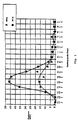
- Fig. 1 is a diagram showing the relationship between the crystal grain size and the frequency.
- Fig. 2 is a diagram showing the relationship between the heating temperature and DSC.
- Fig. 3 is a view showing the mechanism of preventing the damage by neutron irradiation.
- Fig. 4 is a typical view showing the relationship between the neutron irradiation rate and the critical crystal grain size.
- Figs. 5a and 5b show the effect of Fe and Ni exerted on the corrosion resistance of a Zr alloy.
- Fig. 6 is a diagram showing the relationship between the water-fuel volume ratio and the neutron absorption ratio.
- Fig. 7 is a sectional view of a fuel rod.
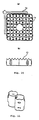
- Figs. 8a and 8b show a perspective view of a channel box.
- Figs. 9a-c show a perspective view of a channel box.
- Figs. 10a and 10b show a plan view of a spacer and a control rod.
- Fig. 11 is a perspective view showing cells in a spacer.
- Fig. 12 is a plan view of a spacer.
- Fig. 13 is a partial sectional view of a water rod.
- Fig. 14 is a partial sectional view of a water rod.
- Fig. 15 is a plan view of a fuel assembly for a high conversion reactor.
- Fig. 16 is a plan view showing a control rod and a fuel assembly in a high conversion reactor.
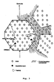
- Fig. 17 is a sectional view showing the structure of the core of a high conversion reactor.
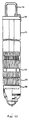
- Fig. 18 is a perspective view of a control rod for a high conversion reactor.
- each of a fuel sheath tube (1), a spacer (13) and channel box (11) constituting a fuel assembly (10) for a nuclear reactor is formed of a Zr alloy; the Zr alloy is refined into an ultra-fine crystal particle size; and the Zr alloy contains alloy elements of Sn, Fe, Ni and Cr mostly dissolved in solid in amounts larger than those in a conventional alloy.
- the Zr alloy contains alloy elements of Sn, Fe, Ni and Cr mostly dissolved in solid in amounts larger than those in a conventional alloy.
- the Zr alloy is added to enhance the strength and corrosion resistance.
- the crystal grain size of a Zr alloy of the present invention is in the range of 1000 nm or less, preferably, in the range of 300 nm or less, particularly, in the range from 10 to 100 nm.
- Sn is added in an amount of 15 wt% or less. It may be added in an amount of 1 to 2 wt% like a conventional Zr alloy; however, the added amount larger than 1 to 2 wt% gives a large effect, and is preferably in the range of from 3 to 7 wt%.
- Fe is added in an amount of 0.05 to 30 wt%. It may be added in an amount of 0.1 to 0.5% like a conventional Zr alloy.
- a conventional Zr alloy precipitations of Fe are formed by the repeating of cold-working and annealing, resulting in the reduced corrosion resistance.
- precipitations of Fe are difficult to be formed and are dissolved in solid, thus increasing the corrosion resistance.
- the content of Fe is in range of 0.5% or more, preferably, in the range of from 1 to 5%.
- Ni is added in an amount of 5 wt% or less. Ni has a high hydrogen absorption property. However, since the Zr alloy of the present invention has an ultra-fine crystal grain size, Ni can be added in an amount of from 0.2% or more. Additionally, at least one kind of Cr, Nb, Mo, Te, Bi and Si may be added in an amount of 5 wt% or less for increasing the strength. In particular, there may be added at least one kind of 0.05 ⁇ 3% of Cr, 0.2 ⁇ 2.5% of Nb, 0.2 ⁇ 1 % of Mo, 0.1 ⁇ 1% of Te, 1 ⁇ 2% of Bi and 0.1 ⁇ 0.5% of Si. Oxygen (O) is added in the alloying of the present invention. The addition of oxygen is effective to suppress the crystal grain growth due to the heating at a high temperature, which leads to the generation of ultra-fine crystal grains.
- Oxygen (O) is added in the alloying of the present invention. The addition of oxygen is effective to suppress the crystal grain growth due to the heating at a high temperature, which leads to the generation of ultra
- the example of the Zr alloy composition (wt%) of an embodiment of the present invention is as follows: (1) A Zr alloy containing 1 ⁇ 5% of Sn and one kind of 0.1 ⁇ 30% of Fe, 0.01 ⁇ 5% of Ni and 0.1 ⁇ 5% of Te. (2) A Ze alloy containing the alloy elements shown in (1) and further 0.1 ⁇ 5% of Cr. (3) A Zr alloy containing 0.5 ⁇ 5% of Nb. (4) A Zr alloy containing the alloy element shown in (3) and further 0.1 ⁇ 5% of Bi. (5) A Zr alloy containing the alloy element shown in (3), and further 0.1 ⁇ 5% of Sn and one kind of 0.2 ⁇ 5% of Mo, 0.1 ⁇ 5% of Fe, 0.01 ⁇ 5% of Ni, and 0.1 ⁇ 5% of Te.
- the Zr alloy having such a metal structure is brittle and is extremely difficult to be worked.
- the Zr alloy can ensure a high ductility.
- the feature of the present invention lies in manufacturing a structural member having an ultra-fine crystal state by working and heat-treatment by use of a material in an ultra-fine crystal state in which such an alloy element is dissolved in solid in Zr.
- a pure Zr powder and alloy powders are mechanically mixed and crushed, to form an alloy powder in a non-equilibrium state (super-saturated solid-solution).
- the pure metal powder may be replaced by a metal powder containing oxygen of 1,000 to 10,000 ppm.
- an oxide powder such as ZrO2 may be added and mixed. The addition of the oxide powder is effective to enhance the crystallization temperature at the time of the subsequent HIP (hot isostatic pressing) for preventing the coarsening of crystal grains during HIP, hot-working and final annealing.
- the alloy powder thus obtained is sintered by HIP, to form a bulk material of a Zr alloy.
- the sintering may be performed at a temperature ( ⁇ 800 degrees C) lower than a re-crystallization temperature for keeping at least part of the alloy powder in a non-equilibrium state after HIP and for preventing the coarsening of an intermetallic compound.
- the sintering may be performed at a temperature lower than the temperature higher than a crystallization temperature of the alloy by about 100 degrees C for preventing the coarsening of crystals and the coarsening of the precipitated intermetallic compound.
- the solution treatment after HIP is not required and it may be omitted.
- the hot-plastic working may be performed at a temperature lower than a re-crystallization temperature, 650 degrees C.
- the cold-plastic working is performed at a draft of 80% or less, and the final annealing is performed at a temperature lower than 800 degrees C.
- Sn and O are elements for increasing the strength
- Fe is an element for reducing the resonance neutron capture cross-section
- Fe, Cr and Ni are elements for increasing the corrosion resistance.
- the composition of each alloy powder after alloying was shown as an MA alloy powder in Table 1.
- the vessel and balls are made of AISI 304 steel.
- Each of the alloy powder No. 1 and the Zr powder contains oxygen of about 900 ppm.
- the alloy powder after mechanical alloying contained oxygen in an amount of about 4,000 ppm.
- the reason why the contents of Sn, Fe, Cr and Ni in the MA alloy powder are higher than those in the raw powder lies in that Zr is stuck on the wall of the vessel of the planetary ball mill, and in that the alloy elements are supplied from the vessel and balls.
- the MA alloy powder No. 1 was observed for the fine structure using a transmission electron microscope, which gave the result that the matrix of the MA alloy powder is made of amorphous crystal surrounding ultra-fine crystals having a crystal grain size of 10 nm or less, and that any dislocation does not exist in the crystal grains although the alloy powder is applied with a forcible work at room temperature.
- Fig. 1 is a graph showing the result of measuring the distribution of the crystal particle size of the MA alloy powder.
- the crystal structure was contained in the alloy powder only in an amount of about 5 vol%, and 90% or more of the crystal grain sizes were in the range of 2 to 10 nm.
- MA mechanical alloying
- the crystallized portion in the alloy powder is reduced, and the whole alloy powder becomes amorphous by the MA for about 200 hr.
- Fig. 2 is a diagram showing the result in which the alloy powder No. 1 is subjected to scanning differential thermal analysis and the re-crystallization temperature is measured.
- the peak of the heat-generation appears at 719 degrees C, which shows a possibility that the holding of the alloy powder for a long period of time at the temperature higher than 719 degrees C causes the re-crystallization of the above-described amorphous structure, leading to the growth of crystal grains.
- the MA alloy powder No. 1 was heated for 5 hr at 800 degrees C, it kept the ultra-fine structure yet while the crystal grains were slightly grown into a size of about 50 nm. Accordingly, it is revealed that the alloy powder No. 1 can keep the ultra-fine structure even by setting the powder processing (solidifying) temperature after MA at a temperature near 800 degrees C.
- the alloy powder No. 1 When being actually heated at 800 degrees C, the alloy powder No. 1 was present substantially as a super-saturated solid-solution without any precipitation phase.
- Fig. 3 shows a damage preventive mechanism for ultra-fine crystals against neutron irradiation.
- atoms are repelled by neutrons and a pair of an interstitial atom and a vacancy are formed.
- the interstitial atoms are bonded to each other to form a loop of a dislocation, which causes the irradiation embrittlement, irradiation growth and the like.
- interstitial atoms and vacancies are present near the crystal boundaries, and accordingly they move and disappear.
- Fig. 4 shows the relationship between the neutron irradiation rate and the critical crystal grain size for preventing the irradiation damage. From the figure, it becomes apparent that in a light water reactor, the irradiation damage can be prevented by setting the crystal grain size to be in the rage of 100 nm or less. Moreover, in a high conversion reactor, the same effect can be obtained by setting the crystal grain size to be in the range of 50 nm or less.
- the neutron irradiation rate is 5x10 ⁇ 8 (dpa/s) and the quantity of irradiation is 7 dpa; and in a high conversion reactor, the former is 3x10 ⁇ 7 dpa/s and the latter is 20 dpa.
- Figs. 5a and 5b show the result of the effect of Fe, Ni and Cr exerted on the corrosion resistance.
- Each of these elements exists at the position of Zr by the replacement with Zr in the oxide film.
- Fe, Ni, and Cr act to trap these conductive electrons thereby lowering the electronic conductivity of the oxide film, resulting in the improved corrosion resistance.
- the probability of replacement of Zr by Fe, Ni, and Cr is significantly increased in a super-saturated solid-solution. Accordingly, in terms of corrosion resistance, the member of a fuel assembly (10), as shown in Fig. 17, of the present invention is extremely excellent.
- Nb having five valence electrons, and Mo and Te having six valence electrons increase the electronic conductivity, so that it seems to lower the corrosion resistance.
- the movement of electrons in the oxide film rate-determines the corrosion of Zr.
- Fig. 6 shows the relationship of a water-fuel volume ratio exerting an effect on the neutron absorption rate (%) represented by the resonance neutron capture cross-section based on the whole neutron generation rate.
- the line shows the state that the resonance neutron capture cross-section of the Zr alloy is reduced by the change in the alloy composition and the strength.
- the resonance neutron capture cross-section is reduced, thus realizing the member of a fuel assembly (10) which has the same characteristics as those of stainless steel.
- the water-fuel volume ratio is set to be in the range of 1.5 or less.
- the ultra-fine crystal powder was subjected to electron irradiation for examining the irradiation resistance. Electron beams of imparting damages equivalent to those obtained by imparting the quality of neutron irradiation of 10 dpa were irradiated, and the fine structure was examined.
- the irradiation temperature was set at 280 degrees C which was equivalent to the water temperature in a nuclear reactor. As a result, the ultra-fine crystal powder showed the very excellent irradiation resistance without any irradiation defect.
- a fuel structural member was manufactured using the alloy powder No. 1 subjected to mechanical alloying for 155 hr in the manner described in Example 1.
- the MA alloy powder was formed and sintered in a cylindrical shape by a hot-isostatic pressing (HIP) at about 800 degrees C. The density was about 98% of the theoretical density.
- the sintered cylindrical body was perforated at the center, to form a hollow billet.
- a pure Zr tube was then inserted in the hollow billet and the end surfaces thereof were welded, thus integrating the alloy hollow billet and the pure Zr tube.
- the integrated tube was subjected to hot-extrusion at 650 degrees C, to form a raw tube. The density of the raw tube almost equals the theoretical density.
- the raw tube was repeatedly and alternately subjected to cold-rolling by a pilger mill and annealing by three times.
- the draft was set at 70%, and the final annealing temperature was set at 600 degrees C, thus obtaining a finished fuel sheath tube having an outside diameter of 12.3 mm and a wall thickness of 0.86 mm.
- an average crystal grain size was smaller than 100 nm, and any precipitation was not recognized and all of the alloy elements are substantially dissolved in solid in the matrix.
- the pure Zr liner layer may be set at a desirable thickness in the range of from 10 to 100 ⁇ m.
- the above-described billet may be set to have an outside diameter of 60 to 70 mm and a thickness of 10 to 12 mm.
- the pure Zr liner layer of the sheath tube was removed by mechanical grinding.
- the resultant sheath tube was kept for 50 hr in steam of 10.3 MPa at 500 degrees C for examining the corrosion resistance.
- the increment by the corrosion was 40 mg/dm2 or less, which showed the very good corrosion resistance.
- a conventional fuel sheath tube was also subjected to the corrosion test under the same condition, which gave the result of the increment of about 50 mg/dm2.
- a fuel rod, shown in Fig. 7 was manufactured using the above sheath tube (1) welded with end plugs made of the same alloy.
- the fuel rod includes an MA alloy sheath tube (1), a pure Zr liner (2), an upper end plug (3), a nuclear fuel pellet (4), a plenum spring (5), a welding portion (6), and a lower end portion (7).
- the welding was performed by a TIG welding method.
- the pure Zr liner (2) had a wall thickness of about 100 ⁇ m.
- the sheath tube (1) is thinned by repeating cold-working and annealing, the orientation of the crystal face of (0002) of Zr having the hexagonal crystal structure tends to be directed at right angles to the planar surface; however, the orientation is difficult to be generated because of the ultra-fine crystal grains. As a result, it seems that the crystal grains are distributed at random to the extent of a Fr value of about 0.25 to 0.35.
- the alloy powder No. 1 (MA: 155 hr) in Example 1 was formed and sintered by HIP, to manufacture a slab.
- the slab was hot-rolled, to enhance the density of the material substantially up to the theoretical value.
- the hot-rolled sheet was repeatedly and alternately subjected to cold-working at a draft of about 30% and vacuum annealing at 600 degrees C, to form a sheet having a thickness of 2 mm.
- the resultant sheet was bent in a U-shape. Two of these sheets were welded to each other, to form an angular cylinder.
- the angular cylinder was shaped in specified dimensions, to form a channel box. In the alloy of this example, any precipitation was not recognized, and alloy elements were dissolved in solid. Figs.
- FIGS. 8a-b and 9a-c are perspective views, wherein Figs. 8a-b shows a straight structure having a constant thickness, and Figs. 9a-c show a structure in which a corner (20) is thicker than that of a side (21). In Fig. 9b, the outside is thicker; and in Fig. 9c, the inside is thicker.
- the shaping was performed by suitably masking the channel box, followed by chemical etching by mixed acid solution of hydrogen fluoride and nitric acid or machining.
- a hexagonal channel box may be obtained.
- the wall thickness may be made constant or corner portions may be made thicker.
- An alloy powder No. 3 of Table 1 in Example 1 was mechanically alloyed in the same manner as in Example 1, and was subjected to HIP, hot-working and cold-working, like the sheath tube, into a shape of a spacer.
- the inside diameter of the tubular spacer was larger than the outside of the sheath tube, and the inside diameter portion of the tubular spacer was not provided the pure Zr liner. It was subjected to hot-extrusion in the state where the pure Zr inner tube was not inserted.
- Fig. 10a shows a plan view
- Fig. 10b shows a side view of a spacer (13) of 8x8 type.
- the spacer (13) is intended to regularly arrange fuel rods as an assembly.
- the spacers (13) in the number of seven pieces or more are disposed in the assembly, and control rods (16) are disposed between the assemblies so as to crossed to each other as shown in the figures.
- the spacer (13) includes 8 ⁇ 10 pieces of cylindrical circular cells (14) for one row, for example, in the arrangement of 8x8, 9x9, and 10x10 (pieces).
- the cell (14) may be formed of the same material as in this example. It can be manufactured in the same process as that of the sheath tube in Example 1 except that the pure Zr was not provided in the hollow billet.
- the spacer (13) and the cell (14) are formed of a high strength material having the above-described composition, either of the spacer (13) and the cell (14) can be thinned to a wall thickness of 0.35 to 0.6 mm. This reduces the average interval between fuels, thus achieving a high conversion reactor.
- Fig. 12 is a plan view of a spacer (13) of 9x9 type and cells (14) disposed therein.
- the average interval between the sheath tubes of 8x8 type shown in Figs. 10a-b can be set at about 3.0 to 4.5 mm; and the average interval for the sheath tube of 9x9 type shown in Fig. 12 can be set at 1.0 to 2.5 mm.
- spacer (13) and cell (14) using an alloy containing alloy elements in increased amounts, the integration of the sheath tube of 9x9 type or 10x10 type can be further increased, and the average interval can be further reduced to be 1 to 2.0 mm.
- the circular cells (14) are welded to each other or fixed on the outer frame of the spacer (13), and spring made holding members are mounted to form a slight space between the sheath tubes.
- the spring made holding member can be also formed of a sheet of the Zr alloy or Ni alloy of the present invention.
- Figs. 13 and 14 are partially sectional plan views each showing a water rod.
- the water rod in this example was manufactured by forming a hollow billet without a pure Zr liner tube by use of each of the alloy Nos. 1 and 2 shown in Table 1 of Example 1 in the same manner as in Example 1; and repeatedly applying, to the hollow billet, the cold-working by the pilger mill and annealing in the same manner as in Example 1.
- a small diameter portion (28) and a large diameter portion (29) shown in Fig. 14, were separately manufactured, and they were integrated with each other by welding.
- Reference numeral (30) designates an end plug.
- Fig. 15 is a sectional view of a fuel assembly for a boiling water type high conversion nuclear reactor according to the present invention.
- the fuel assembly includes a large number of fuel rods (31); seven steps or more of spacers (13) for holding the fuel rods (31) at specified intervals; an angular cylindrical channel box (11) for containing the fuel rods (31) held by the spacers (13); an upper end tie plate (15) and a lower end tie plate (36) for holding both the ends of the fuel rods (31) containing fuel pellets in the fuel sheath tubes (1); and a hanging handle (12) for carrying the whole assembly.
- the fuel channel box (11) contains the fuel rods (31) integrated with each other by the fuel spacers (13).
- the fuel channel box (11) is obtained by joining two-divided U-shaped plates manufactured in Example 2 by plasma welding into an angular cylindrical shape.
- the member acts to regularly run both steam generated on the surfaces of fuel rods (31) and high temperature water flowing between the fuel rods (31), and to forcibly introduce them upward. Since the channel box (11) has the internal pressure being slightly higher than the external pressure, it can be used for a long period in the state that a stress is applied so as to expand the angular cylinder outward.
- the channel box (11) in this example shows the arrangement in which 247 pieces of fuel rods (31) are disposed held by the spacers (13) as shown in Fig. 16.
- the circular cell (14) in the spacer (13) is the same as that in Example 4.
- a high conversion type BWR fuel there is used an MOX fuel in which plutonium is added to enrich depleted uranium or natural uranium.
- plutonium is added to enrich depleted uranium or natural uranium.
- it is required to lower the water-fuel ratio. This can be achieved by disposing fuel rods in a fuel assembly in a closed-pack manner for lowering the amount of a moderator to the fuel.
- the water density can be simply reduced by steam voids in the reactor core, so that the interval between fuel rods can be made large as compared with a pressurized water reactor. This is advantageous not only in cooling fuel but also in manufacturing the assembly.
- the reactor core uses a fuel assembly having a square section and a cross-shaped control rod for minimizing the modification of the nuclear reactor structure.
- a closed-pack triangular arrangement shown in Fig. 16 for lowering the water-fuel ratio.
- the enlargement of the fuel assembly reduces the area of the water gap portion between fuel assemblies.
- the thermal output of the fuel rod per unit length can be made to be similar to that of a conventional reactor core.
- the pressure loss in the reactor core can be reduced by the shortening of the effective length of the fuel rod.
- the water-fuel ratio can be further reduced by adoption of a control rod with a follower (25) in which a zirconium made follower (25), shown in Fig. 18, is provided at the leading edge of an absorption material of the control rod, in addition of the arrangement of the fuel rods.
- a control rod with a follower (25) in which a zirconium made follower (25), shown in Fig. 18, is provided at the leading edge of an absorption material of the control rod, in addition of the arrangement of the fuel rods.
- 247 pieces of the fuel rods are arranged in one channel box.
- Fig. 17 is a sectional view showing the structure of a high conversion reactor.
- the pressure vessel used in the nuclear reactor is not required to be changed in design from that used in a conventional type BWR; but the fuel assembly (10) loaded in the pressure vessel and a control rod guide tube, reactor core supporting plate (19) and an upper grating plate (18) in association with the enlarged control rod must be changed.
- the other parts such as an internal pump system and a steam separator (17)
- the existing structures may be used.
- the high conversion reactor shortens the fuel effective length.
- the control rod is provided with a follower and has the same length as conventional. Accordingly, the fuel channel box is set at the conventional length used for the supporting and guiding the control rod
- the channel box can be supported by the upper end grating plate as in a conventional type BWR, and is not required to be changed in design.
Landscapes
- Chemical & Material Sciences (AREA)
- Engineering & Computer Science (AREA)
- Materials Engineering (AREA)
- Mechanical Engineering (AREA)
- Metallurgy (AREA)
- Organic Chemistry (AREA)
- Physics & Mathematics (AREA)
- Dispersion Chemistry (AREA)
- Plasma & Fusion (AREA)
- General Engineering & Computer Science (AREA)
- High Energy & Nuclear Physics (AREA)
- Powder Metallurgy (AREA)
Applications Claiming Priority (3)
| Application Number | Priority Date | Filing Date | Title |
|---|---|---|---|
| JP06048266A JP3094778B2 (ja) | 1994-03-18 | 1994-03-18 | 軽水炉用燃料集合体とそれに用いられる部品及び合金並びに製造法 |
| JP48266/94 | 1994-03-18 | ||
| JP4826694 | 1994-03-18 |
Publications (2)
| Publication Number | Publication Date |
|---|---|
| EP0674322A1 true EP0674322A1 (fr) | 1995-09-27 |
| EP0674322B1 EP0674322B1 (fr) | 1999-08-11 |
Family
ID=12798643
Family Applications (1)
| Application Number | Title | Priority Date | Filing Date |
|---|---|---|---|
| EP95103966A Expired - Lifetime EP0674322B1 (fr) | 1994-03-18 | 1995-03-17 | Assemblage combustible pour réacteur nucléaire et méthode de fabrication |
Country Status (4)
| Country | Link |
|---|---|
| US (1) | US5596615A (fr) |
| EP (1) | EP0674322B1 (fr) |
| JP (1) | JP3094778B2 (fr) |
| DE (1) | DE69511306T2 (fr) |
Cited By (2)
| Publication number | Priority date | Publication date | Assignee | Title |
|---|---|---|---|---|
| EP0964406A1 (fr) * | 1998-06-12 | 1999-12-15 | Siemens Power Corporation | Alliages de zirconium à haute résistance contenant du bismuth et du niobium |
| EP0964407A1 (fr) * | 1998-06-12 | 1999-12-15 | Siemens Power Corporation | Alliages de zirconium à haute résistance contenant du bismuth, de l'étain et du niobium |
Families Citing this family (25)
| Publication number | Priority date | Publication date | Assignee | Title |
|---|---|---|---|---|
| FR2706066B1 (fr) * | 1993-06-04 | 1995-07-07 | Commissariat Energie Atomique | Combustible nucléaire ayant des propriétés améliorées de rétention des produits de fission. |
| US6221286B1 (en) | 1996-08-09 | 2001-04-24 | Framatome | Nuclear fuel having improved fission product retention properties |
| US5772798A (en) * | 1997-03-25 | 1998-06-30 | Siemens Power Corporation | High strength zirconium alloys containing bismuth |
| US5790623A (en) * | 1997-03-25 | 1998-08-04 | Siemens Power Corporation | Composite cladding for nuclear fuel rods |
| US5768332A (en) * | 1997-03-27 | 1998-06-16 | Siemens Power Corporation | Nuclear fuel rod for pressurized water reactor |
| US5787142A (en) * | 1997-04-29 | 1998-07-28 | Siemens Power Corporation | Pressurized water reactor nuclear fuel assembly |
| GB9926674D0 (en) * | 1999-11-12 | 2000-01-12 | British Nuclear Fuels Plc | Encapsulation of waste |
| KR100441562B1 (ko) * | 2001-05-07 | 2004-07-23 | 한국수력원자력 주식회사 | 우수한 내식성과 기계적 특성을 갖는 지르코늄 합금핵연료 피복관 및 그 제조 방법 |
| JP2003149369A (ja) * | 2001-11-08 | 2003-05-21 | Mitsubishi Nuclear Fuel Co Ltd | 燃料集合体支持格子の製造方法 |
| FR2910912B1 (fr) * | 2006-12-29 | 2009-02-13 | Areva Np Sas | Procede de traitement thermique de desensibilisation a la fissuration assistee par l'environnement d'un alliage a base nickel, et piece realisee en cet alliage ainsi traitee |
| US8116423B2 (en) | 2007-12-26 | 2012-02-14 | Thorium Power, Inc. | Nuclear reactor (alternatives), fuel assembly of seed-blanket subassemblies for nuclear reactor (alternatives), and fuel element for fuel assembly |
| JP5585883B2 (ja) | 2007-12-26 | 2014-09-10 | トリウム・パワー、インク | 核燃料集合体、核燃料集合体を含む軽水炉、及び核燃料集合体の使用方法 |
| CA2748367C (fr) | 2008-12-25 | 2016-11-29 | Thorium Power, Inc. | Assemblage combustible de reacteur a eau legere et element combustible associe |
| JP5430993B2 (ja) * | 2009-03-27 | 2014-03-05 | 株式会社日立製作所 | ジルコニウム材料 |
| US9281083B2 (en) * | 2009-04-06 | 2016-03-08 | Terrapower, Llc | Traveling wave nuclear fission reactor, fuel assembly, and method of controlling burnup therein |
| US8942338B2 (en) * | 2009-04-06 | 2015-01-27 | TerraPower, LLC. | Traveling wave nuclear fission reactor, fuel assembly, and method of controlling burnup therein |
| US10192644B2 (en) | 2010-05-11 | 2019-01-29 | Lightbridge Corporation | Fuel assembly |
| US10170207B2 (en) | 2013-05-10 | 2019-01-01 | Thorium Power, Inc. | Fuel assembly |
| WO2011143172A1 (fr) | 2010-05-11 | 2011-11-17 | Thorium Power, Inc. | Assemblage de combustible à noyau d'alliage de combustibles métalliques et son procédé de fabrication |
| US8774344B1 (en) | 2011-02-10 | 2014-07-08 | Neucon Technology, Llc | Tri-isotropic (TRISO) based light water reactor fuel |
| US9941025B2 (en) * | 2011-04-08 | 2018-04-10 | Terrapower, Llc | Nuclear fuel and method of fabricating the same |
| KR101378066B1 (ko) | 2012-02-28 | 2014-03-28 | 한국수력원자력 주식회사 | 합금원소의 첨가량을 낮추어 부식저항성을 향상시킨 핵연료 피복관용 지르코늄 합금 조성물 및 이를 이용한 지르코늄 합금 핵연료 피복관의 제조방법 |
| CN102925749B (zh) * | 2012-10-16 | 2016-05-04 | 常州大学 | 一种环保型高强度易切削钢用铋锆铁合金及其制备方法 |
| GB2531009A (en) * | 2014-10-07 | 2016-04-13 | Vectura Ltd | Spray Drier Apparatus |
| CN105803263A (zh) * | 2016-02-19 | 2016-07-27 | 西部新锆核材料科技有限公司 | 一种核反应堆燃料包壳用锆合金 |
Citations (5)
| Publication number | Priority date | Publication date | Assignee | Title |
|---|---|---|---|---|
| BE644267A (fr) * | 1963-02-26 | 1964-08-24 | ||
| BE666176A (fr) * | 1964-07-01 | 1965-12-30 | ||
| US3545966A (en) * | 1968-02-27 | 1970-12-08 | Etude La Realisation De Combus | Manufacture of improved nuclear fuels |
| FR2058426A6 (fr) * | 1969-09-02 | 1971-05-28 | Commissariat Energie Atomique | |
| JPS6318030A (ja) * | 1986-07-11 | 1988-01-25 | Nippon Nuclear Fuel Dev Co Ltd | ジルコニウム及びジルコニウム合金並びにその製造方法 |
Family Cites Families (12)
| Publication number | Priority date | Publication date | Assignee | Title |
|---|---|---|---|---|
| US4116682A (en) * | 1976-12-27 | 1978-09-26 | Polk Donald E | Amorphous metal alloys and products thereof |
| US4260416A (en) * | 1979-09-04 | 1981-04-07 | Allied Chemical Corporation | Amorphous metal alloy for structural reinforcement |
| US4391657A (en) * | 1981-07-17 | 1983-07-05 | Bell Telephone Laboratories, Incorporated | Manufacture of niobium-aluminum superconducting material |
| DE3278571D1 (en) * | 1981-07-29 | 1988-07-07 | Hitachi Ltd | Process for producing zirconium-based alloy |
| JPS59179256A (ja) * | 1983-03-31 | 1984-10-11 | Toshiba Corp | 巻鉄心用金属薄帯の製造方法 |
| DE3571096D1 (en) * | 1984-03-09 | 1989-07-20 | Nippon Nuclear Fuel Dev Co | Cladding tube for nuclear fuel and nuclear fuel element having this cladding tube |
| DE3428954A1 (de) * | 1984-08-06 | 1986-02-13 | Kraftwerk Union AG, 4330 Mülheim | Huellrohr aus einer zirkoniumlegierung insbesondere fuer einen kernreaktorbrennstab und verfahren zum herstellen dieses huellrohres |
| JPH0625389B2 (ja) * | 1985-12-09 | 1994-04-06 | 株式会社日立製作所 | 高耐食低水素吸収性ジルコニウム基合金及びその製造法 |
| US5245645A (en) * | 1991-02-04 | 1993-09-14 | Siemens Aktiengesellschaft | Structural part for a nuclear reactor fuel assembly and method for producing this structural part |
| JP2638351B2 (ja) * | 1991-09-20 | 1997-08-06 | 株式会社日立製作所 | 燃料集合体 |
| US5310431A (en) * | 1992-10-07 | 1994-05-10 | Robert F. Buck | Creep resistant, precipitation-dispersion-strengthened, martensitic stainless steel and method thereof |
| US5341407A (en) * | 1993-07-14 | 1994-08-23 | General Electric Company | Inner liners for fuel cladding having zirconium barriers layers |
-
1994
- 1994-03-18 JP JP06048266A patent/JP3094778B2/ja not_active Expired - Fee Related
-
1995
- 1995-03-14 US US08/404,041 patent/US5596615A/en not_active Expired - Fee Related
- 1995-03-17 DE DE69511306T patent/DE69511306T2/de not_active Expired - Fee Related
- 1995-03-17 EP EP95103966A patent/EP0674322B1/fr not_active Expired - Lifetime
Patent Citations (5)
| Publication number | Priority date | Publication date | Assignee | Title |
|---|---|---|---|---|
| BE644267A (fr) * | 1963-02-26 | 1964-08-24 | ||
| BE666176A (fr) * | 1964-07-01 | 1965-12-30 | ||
| US3545966A (en) * | 1968-02-27 | 1970-12-08 | Etude La Realisation De Combus | Manufacture of improved nuclear fuels |
| FR2058426A6 (fr) * | 1969-09-02 | 1971-05-28 | Commissariat Energie Atomique | |
| JPS6318030A (ja) * | 1986-07-11 | 1988-01-25 | Nippon Nuclear Fuel Dev Co Ltd | ジルコニウム及びジルコニウム合金並びにその製造方法 |
Non-Patent Citations (1)
| Title |
|---|
| PATENT ABSTRACTS OF JAPAN vol. 01, no. 2223 (C - 507) 24 June 1988 (1988-06-24) * |
Cited By (3)
| Publication number | Priority date | Publication date | Assignee | Title |
|---|---|---|---|---|
| EP0964406A1 (fr) * | 1998-06-12 | 1999-12-15 | Siemens Power Corporation | Alliages de zirconium à haute résistance contenant du bismuth et du niobium |
| EP0964407A1 (fr) * | 1998-06-12 | 1999-12-15 | Siemens Power Corporation | Alliages de zirconium à haute résistance contenant du bismuth, de l'étain et du niobium |
| US6511556B1 (en) | 1998-06-12 | 2003-01-28 | Siemens Power Corporation | High strength zirconium alloys containing bismuth and niobium |
Also Published As
| Publication number | Publication date |
|---|---|
| JPH07260972A (ja) | 1995-10-13 |
| DE69511306T2 (de) | 1999-12-30 |
| DE69511306D1 (de) | 1999-09-16 |
| EP0674322B1 (fr) | 1999-08-11 |
| US5596615A (en) | 1997-01-21 |
| JP3094778B2 (ja) | 2000-10-03 |
Similar Documents
| Publication | Publication Date | Title |
|---|---|---|
| EP0674322B1 (fr) | Assemblage combustible pour réacteur nucléaire et méthode de fabrication | |
| EP0353733B1 (fr) | Assemblage de combustible pour un réacteur, procédé pour fabrication et membre de structure à cet effet | |
| JP2638351B2 (ja) | 燃料集合体 | |
| DE69405911T2 (de) | Zirkaloy-Hüllrohr mit hoher Risswachstumsfestigkeit | |
| US4810461A (en) | Zirconium-based alloy with high corrosion resistance | |
| JP3218779B2 (ja) | 耐中性子照射脆化に優れた構造部材及びそれに用いるオーステナイト鋼とその用途 | |
| EP0622470A1 (fr) | Procédé pour la fabrication d'un tubage en zircaloy à haute résistance à la propagation des criques | |
| JPH11109072A (ja) | 核燃料棒を被覆する管の製造法、核燃料棒を被覆する管、ジルコニウム合金の製造法および構造部材の製造法 | |
| DE19509257B4 (de) | Verbesserte Kernbrennstoffhülle aus Zirkoniumlegierung | |
| US7127024B2 (en) | Fuel element for a pressurized water reactor | |
| EP1730318A2 (fr) | Alliages au zirconium a capacite anticorrosion amelioree et procede d'elaboration | |
| US4918710A (en) | Fabrication procedure for a cross-bracing grid for a fuel assembly of a nuclear reaction | |
| JPH11148990A (ja) | 核燃料棒を被覆する管の製造法、核燃料被覆管、ジルコニウム合金の製造法および構造部材の製造法 | |
| EP1627090A2 (fr) | Alliage au zirconium et composants pour le coeur de reacteurs nucleaires refroidis a l'eau legere | |
| DE3703168A1 (de) | Brennstoffelement fuer einen atomkernreaktor | |
| DE3248235A1 (de) | Verbundbehaelter fuer kernreaktoren | |
| Meyer et al. | Research reactor fuels | |
| JP3501106B2 (ja) | 軽水炉用燃料集合体とそれに用いられる部品及び合金並びに製造法 | |
| WO1995001639A1 (fr) | Element combustible pour reacteur a eau sous pression possedant des tubes de guidage traites thermiquement en deux etapes | |
| EP0937575A1 (fr) | Elément stratifié et assemblage combustible, utilisant ledit élément | |
| US6690759B1 (en) | Zirconium-base alloy and nuclear reactor component comprising the same | |
| JPH08285975A (ja) | 軽水炉用燃料集合体 | |
| JP2814981B2 (ja) | 燃料集合体 | |
| EP0745258B1 (fr) | Element combustible nucleaire pour reacteur a eau pressurisee et son procede de production | |
| JP2600057B2 (ja) | 高耐食原子燃料用被覆管、スペーサ及びチャンネルボックスとその燃料集合体並びにその製造法 |
Legal Events
| Date | Code | Title | Description |
|---|---|---|---|
| PUAI | Public reference made under article 153(3) epc to a published international application that has entered the european phase |
Free format text: ORIGINAL CODE: 0009012 |
|
| 17P | Request for examination filed |
Effective date: 19950317 |
|
| AK | Designated contracting states |
Kind code of ref document: A1 Designated state(s): DE FR GB SE |
|
| 17Q | First examination report despatched |
Effective date: 19971010 |
|
| GRAG | Despatch of communication of intention to grant |
Free format text: ORIGINAL CODE: EPIDOS AGRA |
|
| GRAG | Despatch of communication of intention to grant |
Free format text: ORIGINAL CODE: EPIDOS AGRA |
|
| GRAH | Despatch of communication of intention to grant a patent |
Free format text: ORIGINAL CODE: EPIDOS IGRA |
|
| GRAH | Despatch of communication of intention to grant a patent |
Free format text: ORIGINAL CODE: EPIDOS IGRA |
|
| GRAA | (expected) grant |
Free format text: ORIGINAL CODE: 0009210 |
|
| AK | Designated contracting states |
Kind code of ref document: B1 Designated state(s): DE FR GB SE |
|
| REF | Corresponds to: |
Ref document number: 69511306 Country of ref document: DE Date of ref document: 19990916 |
|
| ET | Fr: translation filed | ||
| PLBE | No opposition filed within time limit |
Free format text: ORIGINAL CODE: 0009261 |
|
| STAA | Information on the status of an ep patent application or granted ep patent |
Free format text: STATUS: NO OPPOSITION FILED WITHIN TIME LIMIT |
|
| 26N | No opposition filed | ||
| REG | Reference to a national code |
Ref country code: GB Ref legal event code: IF02 |
|
| PGFP | Annual fee paid to national office [announced via postgrant information from national office to epo] |
Ref country code: FR Payment date: 20020319 Year of fee payment: 8 |
|
| PGFP | Annual fee paid to national office [announced via postgrant information from national office to epo] |
Ref country code: SE Payment date: 20020325 Year of fee payment: 8 |
|
| PGFP | Annual fee paid to national office [announced via postgrant information from national office to epo] |
Ref country code: DE Payment date: 20020426 Year of fee payment: 8 |
|
| PGFP | Annual fee paid to national office [announced via postgrant information from national office to epo] |
Ref country code: GB Payment date: 20030307 Year of fee payment: 9 |
|
| PG25 | Lapsed in a contracting state [announced via postgrant information from national office to epo] |
Ref country code: SE Free format text: LAPSE BECAUSE OF NON-PAYMENT OF DUE FEES Effective date: 20030318 |
|
| PG25 | Lapsed in a contracting state [announced via postgrant information from national office to epo] |
Ref country code: DE Free format text: LAPSE BECAUSE OF NON-PAYMENT OF DUE FEES Effective date: 20031001 |
|
| EUG | Se: european patent has lapsed | ||
| PG25 | Lapsed in a contracting state [announced via postgrant information from national office to epo] |
Ref country code: FR Free format text: LAPSE BECAUSE OF NON-PAYMENT OF DUE FEES Effective date: 20031127 |
|
| REG | Reference to a national code |
Ref country code: FR Ref legal event code: ST |
|
| PG25 | Lapsed in a contracting state [announced via postgrant information from national office to epo] |
Ref country code: GB Free format text: LAPSE BECAUSE OF NON-PAYMENT OF DUE FEES Effective date: 20040317 |
|
| GBPC | Gb: european patent ceased through non-payment of renewal fee |
Effective date: 20040317 |