EP0675252A1 - Vorrichtung zur Führung von verschiebbaren Elementen - Google Patents
Vorrichtung zur Führung von verschiebbaren Elementen Download PDFInfo
- Publication number
- EP0675252A1 EP0675252A1 EP95810186A EP95810186A EP0675252A1 EP 0675252 A1 EP0675252 A1 EP 0675252A1 EP 95810186 A EP95810186 A EP 95810186A EP 95810186 A EP95810186 A EP 95810186A EP 0675252 A1 EP0675252 A1 EP 0675252A1
- Authority
- EP
- European Patent Office
- Prior art keywords
- guide
- base plate
- groove
- additional guide
- wing
- Prior art date
- Legal status (The legal status is an assumption and is not a legal conclusion. Google has not performed a legal analysis and makes no representation as to the accuracy of the status listed.)
- Granted
Links
Images




Classifications
-
- E—FIXED CONSTRUCTIONS
- E05—LOCKS; KEYS; WINDOW OR DOOR FITTINGS; SAFES
- E05D—HINGES OR SUSPENSION DEVICES FOR DOORS, WINDOWS OR WINGS
- E05D15/00—Suspension arrangements for wings
- E05D15/06—Suspension arrangements for wings for wings sliding horizontally more or less in their own plane
- E05D15/0621—Details, e.g. suspension or supporting guides
- E05D15/0626—Details, e.g. suspension or supporting guides for wings suspended at the top
- E05D15/0656—Bottom guides
-
- E—FIXED CONSTRUCTIONS
- E05—LOCKS; KEYS; WINDOW OR DOOR FITTINGS; SAFES
- E05Y—INDEXING SCHEME ASSOCIATED WITH SUBCLASSES E05D AND E05F, RELATING TO CONSTRUCTION ELEMENTS, ELECTRIC CONTROL, POWER SUPPLY, POWER SIGNAL OR TRANSMISSION, USER INTERFACES, MOUNTING OR COUPLING, DETAILS, ACCESSORIES, AUXILIARY OPERATIONS NOT OTHERWISE PROVIDED FOR, APPLICATION THEREOF
- E05Y2201/00—Constructional elements; Accessories therefor
- E05Y2201/40—Motors; Magnets; Springs; Weights; Accessories therefor
- E05Y2201/47—Springs
-
- E—FIXED CONSTRUCTIONS
- E05—LOCKS; KEYS; WINDOW OR DOOR FITTINGS; SAFES
- E05Y—INDEXING SCHEME ASSOCIATED WITH SUBCLASSES E05D AND E05F, RELATING TO CONSTRUCTION ELEMENTS, ELECTRIC CONTROL, POWER SUPPLY, POWER SIGNAL OR TRANSMISSION, USER INTERFACES, MOUNTING OR COUPLING, DETAILS, ACCESSORIES, AUXILIARY OPERATIONS NOT OTHERWISE PROVIDED FOR, APPLICATION THEREOF
- E05Y2201/00—Constructional elements; Accessories therefor
- E05Y2201/60—Suspension or transmission members; Accessories therefor
- E05Y2201/622—Suspension or transmission members elements
- E05Y2201/684—Rails; Tracks
-
- E—FIXED CONSTRUCTIONS
- E05—LOCKS; KEYS; WINDOW OR DOOR FITTINGS; SAFES
- E05Y—INDEXING SCHEME ASSOCIATED WITH SUBCLASSES E05D AND E05F, RELATING TO CONSTRUCTION ELEMENTS, ELECTRIC CONTROL, POWER SUPPLY, POWER SIGNAL OR TRANSMISSION, USER INTERFACES, MOUNTING OR COUPLING, DETAILS, ACCESSORIES, AUXILIARY OPERATIONS NOT OTHERWISE PROVIDED FOR, APPLICATION THEREOF
- E05Y2600/00—Mounting or coupling arrangements for elements provided for in this subclass
- E05Y2600/10—Adjustable
- E05Y2600/13—Adjustable by motors, magnets, springs or weights
-
- E—FIXED CONSTRUCTIONS
- E05—LOCKS; KEYS; WINDOW OR DOOR FITTINGS; SAFES
- E05Y—INDEXING SCHEME ASSOCIATED WITH SUBCLASSES E05D AND E05F, RELATING TO CONSTRUCTION ELEMENTS, ELECTRIC CONTROL, POWER SUPPLY, POWER SIGNAL OR TRANSMISSION, USER INTERFACES, MOUNTING OR COUPLING, DETAILS, ACCESSORIES, AUXILIARY OPERATIONS NOT OTHERWISE PROVIDED FOR, APPLICATION THEREOF
- E05Y2600/00—Mounting or coupling arrangements for elements provided for in this subclass
- E05Y2600/40—Mounting location; Visibility of the elements
- E05Y2600/452—Mounting location; Visibility of the elements in or on the floor or wall
-
- E—FIXED CONSTRUCTIONS
- E05—LOCKS; KEYS; WINDOW OR DOOR FITTINGS; SAFES
- E05Y—INDEXING SCHEME ASSOCIATED WITH SUBCLASSES E05D AND E05F, RELATING TO CONSTRUCTION ELEMENTS, ELECTRIC CONTROL, POWER SUPPLY, POWER SIGNAL OR TRANSMISSION, USER INTERFACES, MOUNTING OR COUPLING, DETAILS, ACCESSORIES, AUXILIARY OPERATIONS NOT OTHERWISE PROVIDED FOR, APPLICATION THEREOF
- E05Y2600/00—Mounting or coupling arrangements for elements provided for in this subclass
- E05Y2600/40—Mounting location; Visibility of the elements
- E05Y2600/46—Mounting location; Visibility of the elements in or on the wing
-
- E—FIXED CONSTRUCTIONS
- E05—LOCKS; KEYS; WINDOW OR DOOR FITTINGS; SAFES
- E05Y—INDEXING SCHEME ASSOCIATED WITH SUBCLASSES E05D AND E05F, RELATING TO CONSTRUCTION ELEMENTS, ELECTRIC CONTROL, POWER SUPPLY, POWER SIGNAL OR TRANSMISSION, USER INTERFACES, MOUNTING OR COUPLING, DETAILS, ACCESSORIES, AUXILIARY OPERATIONS NOT OTHERWISE PROVIDED FOR, APPLICATION THEREOF
- E05Y2800/00—Details, accessories and auxiliary operations not otherwise provided for
- E05Y2800/34—Form stability
- E05Y2800/342—Deformable
-
- E—FIXED CONSTRUCTIONS
- E05—LOCKS; KEYS; WINDOW OR DOOR FITTINGS; SAFES
- E05Y—INDEXING SCHEME ASSOCIATED WITH SUBCLASSES E05D AND E05F, RELATING TO CONSTRUCTION ELEMENTS, ELECTRIC CONTROL, POWER SUPPLY, POWER SIGNAL OR TRANSMISSION, USER INTERFACES, MOUNTING OR COUPLING, DETAILS, ACCESSORIES, AUXILIARY OPERATIONS NOT OTHERWISE PROVIDED FOR, APPLICATION THEREOF
- E05Y2900/00—Application of doors, windows, wings or fittings thereof
- E05Y2900/10—Application of doors, windows, wings or fittings thereof for buildings or parts thereof
- E05Y2900/13—Type of wing
- E05Y2900/132—Doors
-
- E—FIXED CONSTRUCTIONS
- E05—LOCKS; KEYS; WINDOW OR DOOR FITTINGS; SAFES
- E05Y—INDEXING SCHEME ASSOCIATED WITH SUBCLASSES E05D AND E05F, RELATING TO CONSTRUCTION ELEMENTS, ELECTRIC CONTROL, POWER SUPPLY, POWER SIGNAL OR TRANSMISSION, USER INTERFACES, MOUNTING OR COUPLING, DETAILS, ACCESSORIES, AUXILIARY OPERATIONS NOT OTHERWISE PROVIDED FOR, APPLICATION THEREOF
- E05Y2900/00—Application of doors, windows, wings or fittings thereof
- E05Y2900/10—Application of doors, windows, wings or fittings thereof for buildings or parts thereof
- E05Y2900/13—Type of wing
- E05Y2900/148—Windows
-
- Y—GENERAL TAGGING OF NEW TECHNOLOGICAL DEVELOPMENTS; GENERAL TAGGING OF CROSS-SECTIONAL TECHNOLOGIES SPANNING OVER SEVERAL SECTIONS OF THE IPC; TECHNICAL SUBJECTS COVERED BY FORMER USPC CROSS-REFERENCE ART COLLECTIONS [XRACs] AND DIGESTS
- Y10—TECHNICAL SUBJECTS COVERED BY FORMER USPC
- Y10S—TECHNICAL SUBJECTS COVERED BY FORMER USPC CROSS-REFERENCE ART COLLECTIONS [XRACs] AND DIGESTS
- Y10S16/00—Miscellaneous hardware, e.g. bushing, carpet fastener, caster, door closer, panel hanger, attachable or adjunct handle, hinge, window sash balance
- Y10S16/06—Anti-rattle
Definitions
- the present invention relates to a device for guiding displaceable elements, in particular laterally displaceable doors, windows, partitions, shutters and covers, according to the preamble of patent claim 1.
- Sliding doors that can be operated using minimal space are increasingly used in private, industrial and commercial areas.
- the assembled sliding doors are usually in a guide on the top, e.g. a track, slidably mounted. So that the sliding door when opening without hitting the side, e.g. can be moved into an opening provided for this purpose, a further guide element or an additional guide is often provided on the underside of the door.
- Known additional guides have the shape of a metal wing which rigidly projects into a guide groove provided in the underside of the door.
- the present invention is therefore based on the object of providing a device for guiding displaceable elements, in particular by means of which the noises which occur when the sliding elements are at a standstill are eliminated.
- the device according to the invention eliminates the noises caused by the displaceable elements when stationary. Furthermore, the device, which is inexpensive to produce and can be assembled without additional effort, further improves the smoothness of the displacement of the elements. Material shrinkage occurring in the sliding elements is compensated for by the device according to the invention, as a result of which the clamping and blocking known with rigid guide elements is avoided.
- Fig. 1 shows a sliding door TB, which is slidably mounted in an upper guide.
- the upper guide consists of a guide rail FS on which a roller R is guided, which is connected to the sliding door TB via an axis and a connecting element VE.
- the sliding door TB has a guide groove FN on the underside, into which an additional guide BF connected to the floor projects.
- the known additional guide BF prevents the sliding door TB from tilting down and hanging out of the upper guide or from hitting an adjacent wall. As described at the outset, however, this device has the problem that the sliding door TB strikes the additional guide BF when air movements occur and causes disturbing noises.
- FIGS. 2 to 9 show an additional guide BF1, which consists of a base plate BP which can be connected to the floor or a side wall and a U-shaped element UP which is connected to the base plate BP, the two wings UFF1, UFF2 and an intermediate piece UF connecting the wings UFF1, UFF2 having.
- the wings UFF1, UFF2 are close to the Base plate BP is connected to one another by an axis AX1, on which a tilting element KE is mounted such that it can be tilted into or out of the opening of the U-shaped element UP.
- a stop is preferably provided, against which the tilting element KE is pressed by means of an elastic element FE1, as long as the additional guide BF1 is not mounted.
- a leaf or spiral spring FE1 is suitable as an elastic element, for example, which presses on the one hand against the intermediate piece UF and on the other hand against the tilting element KE.
- the additional guide BF1 is shown in the assembled state in FIG. 2a.
- the U-shaped element UP and the tilting element KE protrude into the U-shaped guide groove FN provided on the underside of the sliding door TB in such a way that the intermediate piece UF and the tilting element KE bear in parallel on the groove sides NS1 and NS2 of the guide groove FN. Due to the force exerted by the spring FE1, the tilting element KE pushes the groove side NS2 outwards until the groove side NS1 bears against the intermediate piece UF.
- the groove sides NS1 and NS2 are therefore in constant contact with the additional guide BF1, so that mutual contact of the groove sides NS1 and NS2 on the additional guide BF1 is prevented both when the door is at a standstill and when the door TB is moved. The occurrence of disturbing noises is therefore avoided.
- the base plate BP and the U-shaped element UP are preferably produced in one casting.
- the additional guide BF1 shown in FIG. 2 could also be expanded by using an H-shaped element (instead of the U-shape) in which a tilting element KE is provided on each groove side NS1 or NS2.
- a tilting element KE is provided on each groove side NS1 or NS2.
- a hardwood or plastic insert KEL is also provided in the guide groove FN, which is selected in accordance with the material used for the additional guide BF1 in such a way that only slight frictional forces occur when the door TB is moved.
- the length of the wings UFF1, UFF2 of the U-shaped element UP is preferably chosen such that the additional guide BF1 still has the function of the additional guide BF not shown in FIG. 1 in the event of failure of one of the movable parts FE1, KE, AX1.
- This measure is preferably also applied analogously to the additional guides BF2, ..., BF7 described below.
- FIG. 3 shows an additional guide BF2, which consists of a base plate BP and a wing FL1 connected to it and standing perpendicularly thereon, which is enclosed by a leaf spring BLF1, which is curved outwards on the wing sides.
- a sectional view of the mounted additional guide BF2 is shown in Fig. 3b.
- the wing FL1 runs within the guide groove FN of the sliding door TB.
- the curvatures BWR, BWF of the leaf spring BLF1 are in contact with the groove sides NS1 and NS2 and press them elastically outwards so that the sliding door TB is guided without play both when it is at a standstill and when it is being moved.
- the ends FLE of the wing FL1 have a larger cross section, so that the leaf spring BLF1 is held immovably on both sides. Further the wing ends FLE are dimensioned such that, in the event of failure of the leaf spring BLF1, the function of the additional guide BF not shown in FIG. 1 remains guaranteed.
- This minimal function is to be performed in the additional guide BF3 shown in FIG. 4 by wing parts FLT which are connected to the base plate BP.
- the base plate BP is also connected via an axis AX2 to a rotary wing DFL, the ends of which are each connected to a roller ADR via further axes AX3.
- the additional guide BF3 is also provided with an elastic element, e.g. a spiral spring FE2 connected, which rotates the rotary wing DFL relative to the base plate BP about the axis AX2.
- the rotary movement is preferably limited by a stop.
- 4b shows a sectional illustration of the mounted additional guide BF3.
- rollers ADR are pressed by the force of the spring FE2 against the groove sides NS1 or NS2 of the guide groove FN, as a result of which the sliding door TB is held or guided free of play and noise both when it is at a standstill and when it is being moved.
- FIG. 5 shows a further additional guide BF4 provided with a wing FL2, which is connected at least on one side of the wing FL2 to a curved leaf spring BLF2a or BLF2b, which is held on one side by a fastening element SRW.
- the leaf spring BLF2a has a slot SL into which a cam NK connected to the wing FL2 projects. When the leaf spring BLF2 is pressed on, it is therefore guided through the cam NK.
- the hatched curvature BW of the leaf spring BLF2a presses after mounting the additional guide BF4 against the groove sides NS1 or NS2 of the guide groove FN, whereby the sliding door TB is again held or guided without noise.
- leaf springs BLF2a, BLF2b are provided on both sides of the wing FL2, their curvatures are preferably provided opposite one another. This prevents torque from being exerted on the mounted additional guide BF4 by the sliding door TB.
- FIG. 6 shows a further additional guide BF5, which has a base plate BP, a wing IFL and two elastic elements or spring elements FF1, FF2, which are provided for pressing against the groove sides NS1 and NS2 of the guide groove FN.
- the spring elements FF1, FF2 can preferably only be pressed against the wing IFL until they strike a stop AS. It is particularly advantageous with this additional guide BF5 that the base plate BP, the wing IFL and the spring elements FF1, FF2 are manufactured in one piece with little manufacturing effort. The purchase and installation of e.g. Leaf springs BLF shown in FIG. 5 are therefore omitted.
- FIG. 7 shows an additional guide BF6, which has a roller ADR2, which is pressed into an approximately V-shaped lower guide groove FNV of a sliding door TB.
- the roller ADR2 is connected to the base plate BP via a lever AH via a joint (axis AX4, wing FL3).
- the lever AH is pressed vertically upwards by an elastic element, for example a spiral spring FE3, so that the roller ADR2 contacted both sides NS1, NS2 of the guide groove FNV.
- an elastic element for example a spiral spring FE3
- FIG. 8 shows a further additional guide BF7 with a guide element SCH which can be displaced vertically into an approximately V-shaped lower guide groove FNV of a sliding door TB.
- the guide element SCH is held by an axis AX5, which is guided at the ends in slots SFR, which are provided in a U-shaped holder H connected to the base plate BP.
- an elastic element e.g. a coil spring FE4 is provided. Vibrations of the sliding door TB are transmitted to and absorbed by the elastic element FE4, as in the previously described additional guides BF1, ..., BF6.
- Elastic elements which have a high absorption capacity are therefore preferably chosen.
- springs e.g. known hydraulic dampers are used.
- a hydraulic damper DE is arranged in FIG. 7 parallel to the spiral spring FE3.
- the additional guide BF1, ..., BF7 can also be arranged on the outside of the sliding door TB.
- elastic elements which preferably act against the sliding door TB from both sides, vibrations could be dissipated to the additional guide BF and an impact on the latter could be prevented.
- 9 shows a U-shaped additional guide BF8, in which a sliding door TB is guided and held.
- Two additional guides BF known from FIG. 7 form the wing parts USL, USR of the additional guide BF8, which are connected to one another via an intermediate piece UB.
- this additional guide BF8 requires more space, is more complex to manufacture and leaves traces on the underside of the sliding door TB.
- the device according to the invention can be used for any sliding elements such as doors, windows, partitions, covers, etc.
- the additional guides BF1, ..., BF8 are therefore either mounted on the floor or on a wall.
- the elements provided on the base plates BP (the U-shaped element UP in FIG. 2, the wings FL1, FL2 in FIGS. 3 and 5, the rotating wing DFL in FIG. 4, the rocker arm AH in FIG. 7, and the holder H in Fig. 8) arranged transversely to the running direction of the sliding door TB and locked. This makes it easier to adjust the additional guides BF1, ..., BF8 according to the course of the sliding door TB or the guide groove FN, FNV.
- the device according to the invention can also be used advantageously if the sliding element (TB) is to be guided on the underside by a running rail and on the top by an additional guide BF1, ..., BF8.
Landscapes
- Engineering & Computer Science (AREA)
- Mechanical Engineering (AREA)
- Feeding Of Articles By Means Other Than Belts Or Rollers (AREA)
- Moving Of Heads (AREA)
- Casings For Electric Apparatus (AREA)
- Support Devices For Sliding Doors (AREA)
- Wing Frames And Configurations (AREA)
- Closing And Opening Devices For Wings, And Checks For Wings (AREA)
- Knitting Machines (AREA)
- Magnetic Bearings And Hydrostatic Bearings (AREA)
Abstract
Description
- Die vorliegende Erfindung betrifft eine Vorrichtung zur Führung von verschiebbaren Elementen, insbesondere von seitlich verschiebbaren Türen, Fenstern, Trennwänden, Läden und Abdeckungen, nach dem Oberbegriff des Patentanspruchs 1.
- Schiebetüren, die unter Inanspruchnahme von minimalem Platzbedarf bedient werden können, kommen heute in privaten, industriellen und gewerblichen Bereichen vermehrt zur Anwendung. Die montierten Schiebetüren sind dabei normalerweise an der Oberseite in einer Führung, z.B. einer Laufschiene, verschiebbar gelagert. Damit die Schiebetür beim Öffnen, ohne seitlich anzustossen, z.B. in eine dafür vorgesehene Öffnung verschiebbar ist, ist auf der Türunterseite oft ein weiteres Führungselement bzw. eine Zusatzführung vorgesehen. Bekannte Zusatzführungen weisen die Form eines Metallflügels auf, der starr in eine in der Türunterseite vorgesehene Führungsnut hineinragt. Diese oben beschriebenen Vorrichtungen, die zum Öffnen und Schliessen von Fenstern dienen, werden allgemein als Beschläge bezeichnet.
- Bei der Konstruktion von Beschlägen, die zur Führung der Schiebetüren dienen, wird darauf geachtet, dass eine einfache Montierbarkeit, eine zuverlässige Funktion und ein ruhiger Lauf der Türen gewährleistet ist. Aus der EP 0 312 777 A1 ist z.B. ein von koaxialen Rollen getragenes Schiebetor bekannt, das schwingungsarm verschiebbar ist.
- Obwohl die mit bekannten Beschlägen versehenen Schiebetüren gute Laufeigenschaften aufweisen, macht sich nachteilig bemerkbar, dass sie im Stillstand nach wie vor störende Geräusche verursachen können. Diese Geräusche werden durch das Anschlagen des Türblattes gegen die auf der Türunterseite vorgesehene Zusatzführung verursacht, wenn Luftbewegungen auftreten, welche die Schiebetür erfassen. Die dadurch entstehenden Klapper- und Schlaggeräusche werden insbesondere bei allgemein niedrigem Geräuschpegel, z.B. in der Nacht, als störend empfunden.
- Der vorliegenden Erfindung liegt daher die Aufgabe zugrunde, eine Vorrichtung zur Führung von verschiebbaren Elementen zu schaffen, durch die insbesondere die beim Stillstand der Schiebeelemente auftretenden Geräusche beseitigt werden.
- Diese Aufgabe wird durch die im kennzeichnenden Teil des Patentanspruchs 1 angegebenen Massnahmen gelöst. Vorteilhafte Ausgestaltungen der Erfindung sind in weiteren Ansprüchen angegeben.
- Durch die erfindungsgemässe Vorrichtung werden die beim Stillstand durch die verschiebbaren Elemente verursachten Geräusche beseitigt. Ferner wird durch die Vorrichtung, die kostengünstig herstellbar und ohne zusätzlichen Aufwand montierbar ist, eine weitere Verbesserung der Laufruhe bei der Verschiebung der Elemente erzielt. In den Schiebeelementen auftretender Materialschwund wird durch die erfindungsgemässe Vorrichtung kompensiert, wodurch das bei starren Führungselementen bekannte Klemmen und Blockieren vermieden wird.
- Die Erfindung wird nachfolgend anhand einer Zeichnung beispielsweise näher erläutert. Dabei zeigt:
- Fig. 1 ein in einer oberen und unteren Führung verschiebbar gelagertes Element
- Fig. 2 eine untere Führung (Zusatzführung), die ein seitlich kippbares Element aufweist
- Fig. 3 eine Zusatzführung mit einer Blattfeder
- Fig. 4 eine Zusatzführung mit einem Drehflügel und Rollen
- Fig. 5 eine Zusatzführung, die beidseitig mit je einer Blattfeder versehen ist
- Fig. 6 eine Zusatzführung mit zwei durchgehend verbundenen Federelementen
- Fig. 7 eine Zusatzführung mit einem vertikal verschiebbaren Hebel und einer Rolle
- Fig. 8 eine Zusatzführung mit einem vertikal verschiebbaren Element
- Fig. 9 eine U-förmige Zusatzführung, in der das Schiebeelement führbar ist
- Fig. 1 zeigt eine Schiebetür TB, die in einer oberen Führung verschiebbar gelagert ist. Die obere Führung besteht dabei aus einer Führungsschiene FS auf der eine Rolle R geführt ist, die über eine Achse und ein Verbindungselement VE mit der Schiebetür TB verbunden ist. Die Schiebetür TB weist auf der Unterseite eine Führungsnut FN auf, in die eine mit dem Boden verbundene Zusatzführung BF hineinragt. Durch die bekannte Zusatzführung BF wird verhindert, dass die Schiebetür TB unten wegkippen und aus der oberen Führung aushängen oder an eine angrenzende Wand anschlagen kann. Wie eingangs beschrieben, besteht bei dieser Vorrichtung jedoch das Problem, dass die Schiebetür TB bei auftretenden Luftbewegungen gegen die Zusatzführung BF anschlägt und störende Geräusche verursacht. Das in der Führungsnut FN vorhandene Spiel, das diese Bewegungen zulässt, ist jedoch notwendig, um ein Verklemmen der Zusatzführung BF innerhalb der Führungsnut FN zu verhindern. Dieses Spiel wird ferner immer genügend gross gewählt, um auftretenden Änderungen des Materials (Temperaturdehnungen, Dehnungen aufgrund wechselnder Feuchtigkeit, etc.) zu begegnen.
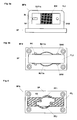
- Mittels der in den Figuren 2 bis 9 beschriebenen erfindungsgemässen Zusatzführungen BF1,..., BF8 gelingt die Beseitigung der oben beschriebenen Probleme. Fig. 2 zeigt eine Zusatzführung BF1, die aus einer mit dem Boden oder einer Seitenwand verbindbaren Basisplatte BP und einem mit der Basisplatte BP verbundenen U-förmigen Element UP besteht, das zwei Flügel UFF1, UFF2 und ein die Flügel UFF1, UFF2 verbindendes Zwischenstück UF aufweist. Die Flügel UFF1, UFF2 sind nahe der Basisplatte BP durch eine Achse AX1 miteinander verbunden, auf welcher ein Kippelement KE derart gelagert ist, dass es in die Öffnung des U-förmigen Elements UP hinein- oder aus dieser hinausgekippt werden kann. Vorzugsweise ist zur Begrenzung der Auslenkung des Kippelementes KE nach aussen ein Anschlag vorgesehen, gegen den das Kippelement KE mittels einem elastischen Element FE1 gedrückt wird, solange die Zusatzführung BF1 nicht montiert ist. Als elastisches Element ist beispielsweise eine Blatt- oder Spiralfeder FE1 geeignet, welche einerseits gegen das Zwischenstück UF und andererseits gegen das Kippelement KE drückt. In Fig. 2a ist die Zusatzführung BF1 in montiertem Zustand dargestellt. Das U-förmige Element UP und das Kippelement KE ragen dabei derart in die an der Unterseite der Schiebetür TB vorgesehene U-förmige Führungsnut FN hinein, dass das Zwischenstück UF und das Kippelement KE parallel an den Nutseiten NS1 bzw. NS2 der Führungsnut FN anliegen. Durch die von der Feder FE1 ausgeübte Kraft drückt das Kippelement KE die Nutseite NS2 nach aussen, bis die Nutseite NS1 am Zwischenstück UF anliegt. Die Nutseiten NS1 und NS2 sind daher andauernd mit der Zusatzführung BF1 in Kontakt, so dass ein gegenseitiges Anschlagen der Nutseiten NS1 und NS2 an die Zusatzführung BF1 sowohl im Stillstand als auch beim Verschieben der Tür TB verhindert wird. Das Auftreten von störenden Geräuschen wird daher vermieden.
- Vorzugsweise werden die Basisplatte BP und das U-förmige Element UP in einem Guss gefertigt. Die in Fig. 2 gezeigte Zusatzführung BF1 könnte ferner durch die Verwendung eines H-förmigen Elements (anstatt der U-Form) erweitert werden, in dem auf jeder Nutseite NS1 bzw. NS2 ein Kippelement KE vorgesehen ist. Dabei wird vorzugsweise nur ein elastisches Element FE1 verwendet, das die beiden Kippelemente KE nach aussen gegen die Nutseiten NS1 und NS2 stösst. In Fig. 2b ist in der Führungsnut FN ferner ein Hartholz- oder Kunststoffeinleger KEL vorgesehen, der entsprechend dem für die Zusatzführung BF1 verwendeten Material so gewählt ist, dass nur geringe Reibungskräfte beim Verschieben der Tür TB auftreten. Die Länge der Flügel UFF1, UFF2 des U-förmigen Elements UP ist vorzugsweise derart gewählt, dass die Zusatzführung BF1 beim Ausfall eines der beweglichen Teile FE1, KE, AX1, noch die Funktion der nichterfindungsgemässen in Fig. 1 gezeigten Zusatzführung BF aufweist. Diese Massnahme wird vorzugsweise auch bei den nachfolgend beschriebenen Zusatzführungen BF2, ..., BF7 sinngemäss angewendet.
- In Fig. 3 ist eine Zusatzführung BF2 gezeigt, die aus einer Basisplatte BP und einem damit verbundenen und senkrecht darauf stehenden Flügel FL1 besteht, der von einer Blattfeder BLF1 umschlossen ist, die auf den Flügelseiten nach aussen gewölbt ist. Eine Schnittdarstellung der montierten Zusatzführung BF2 ist in Fig. 3b gezeigt. Der Flügel FL1 verläuft dabei innerhalb der Führungsnut FN der Schiebetür TB. Die Wölbungen BWR, BWF der Blattfeder BLF1 sind in Kontakt mit den Nutseiten NS1 bzw. NS2 und drücken diese elastisch nach aussen, so dass die Schiebetür TB sowohl im Stillstand aus auch beim Verschieben spielfrei geführt ist. Die Enden FLE des Flügels FL1 weisen einen grösseren Querschnitt auf, so dass die Blattfeder BLF1 beidseitig unverschiebbar gehalten ist. Ferner sind die Flügelenden FLE derart dimensioniert, dass beim Ausfall der Blattfeder BLF1 noch die Funktion der nichterfindungsgemässen in Fig. 1 gezeigten Zusatzführung BF gewährleistet bleibt.
- Diese Minimalfunktion soll in der in Fig. 4 gezeigten Zusatzführung BF3 durch Flügelteile FLT wahrgenommen werden, die mit der Basisplatte BP verbunden sind. Die Basisplatte BP ist ferner über eine Achse AX2 mit einem Drehflügel DFL verbunden, dessen Enden über weitere Achsen AX3 je mit einer Rolle ADR verbunden sind. Die Zusatzführung BF3 ist ferner mit einem elastischen Element, z.B. einer Spiralfeder FE2 verbunden, welche den Drehflügel DFL relativ zur Basisplatte BP um die Achse AX2 dreht. Vorzugsweise ist die Drehbewegung durch einen Anschlag begrenzt. Fig. 4b zeigt eine Schnittdarstellung der montierten Zusatzführung BF3. Daraus ist ersichtlich, dass die Rollen ADR durch die Kraft der Feder FE2 gegen die Nutseiten NS1 bzw. NS2 der Führungsnut FN gedrückt werden, wodurch die Schiebetür TB sowohl im Stillstand, als auch beim Verschieben spiel- und geräuschfrei gehalten bzw. geführt wird.
- Fig. 5 zeigt eine weitere mit einem Flügel FL2 versehene Zusatzführung BF4, die zumindest an einer Seite des Flügels FL2 mit einer gewölbten Blattfeder BLF2a bzw. BLF2b verbunden ist, die auf einer Seite von einem Befestigungselement SRW gehalten wird. Auf der anderen Seite weist die Blattfeder BLF2a einen Schlitz SL auf, in den ein mit dem Flügel FL2 verbundener Nocken NK hineinragt. Beim Andrücken der Blattfeder BLF2 wird diese daher durch den Nocken NK geführt. Die schraffiert gezeichnete Wölbung BW der Blattfeder BLF2a drückt nach Montage der Zusatzführung BF4 gegen die Nutseiten NS1 bzw. NS2 der Führungsnut FN, wodurch die Schiebetür TB wiederum geräuschfrei gehalten bzw. geführt wird. Falls, wie in Fig. 5b gezeigt, beidseits des Flügels FL2 Blattfedern BLF2a, BLF2b vorgesehen sind, werden deren Wölbungen vorzugsweise einander gegenüberliegend vorgesehen. Dadurch wird verhindert, dass durch die Schiebetür TB ein Drehmoment auf die montierte Zusatzführung BF4 ausgeübt wird.
- Fig. 6 zeigt eine weitere Zusatzführung BF5, die eine Basisplatte BP, einen Flügel IFL und zwei elastische Elemente bzw. Federelemente FF1, FF2 aufweist, die zum Andrücken gegen die Nutseiten NS1 bzw. NS2 der Führungsnut FN vorgesehen sind. Die Federelemente FF1, FF2 lassen sich vorzugsweise nur soweit gegen den Flügel IFL drücken, bis sie auf einen Anschlag AS auftreffen. Besonders vorteilhaft bei dieser Zusatzführung BF5 ist, dass die Basisplatte BP, der Flügel IFL und die Federelemente FF1, FF2 mit geringem Herstellungsaufwand aus einem Stück gefertigt sind. Die Anschaffung und die Montage der z.B. in Fig. 5 gezeigten Blattfedern BLF entfällt daher.
- Fig. 7 zeigt eine Zusatzführung BF6, die eine Rolle ADR2 aufweist, welche in eine annähernd V-förmige untere Führungsnut FNV einer Schiebetür TB gedrückt wird. Die Rolle ADR2 ist über einen Hebel AH über ein Gelenk (Achse AX4, Flügel FL3) mit der Basisplatte BP verbunden. Der Hebel AH wird von einem elastischen Element, z.B. einer Spiralfeder FE3 vertikal nach oben gedrückt, so dass die Rolle ADR2 beide Seiten NS1, NS2 der Führungsnut FNV kontaktiert. Dadurch wird die Schiebetür TB wiederum gehalten oder geführt, ohne dass die Tür gegen die Zusatzführung BF6 anschlägt und Geräusche verursacht.
- Fig. 8 zeigt eine weitere Zusatzführung BF7 mit einem Führungselement SCH, das vertikal in eine annähernd V-förmige untere Führungsnut FNV einer Schiebetür TB verschiebbar ist. Das Führungselement SCH ist von einer Achse AX5 gehalten, die an den Enden in Schlitzen SFR geführt ist, die in einer U-förmigen, mit der Basisplatte BP verbundenen Halterung H vorgesehen sind. Zur vertikalen Verschiebung des Führungselementes SCH ist ein elastisches Element. z.B. eine Spiralfeder FE4 vorgesehen. Vibrationen der Schiebetür TB werden dadurch, wie bei den vorgängig beschriebenen Zusatzführungen BF1, ..., BF6 auf das elastische Element FE4 übertragen und von diesem absorbiert. Vorzugsweise werden daher elastische Elemente gewählt, die über ein hohes Absorptionsvermögen verfügen. Zusätzlich zu Federn könnten z.B. bekannte hydraulische Dämpfer eingesetzt werden. In Fig. 7 ist zu diesem Zweck ein hydraulischer Dämpfer DE parallel zur Spiralfeder FE3 angeordnet.
- Falls genügend Platz vorhanden ist und eine Führungsnut an der Unterseite der Schiebetür TB zu vermeiden ist, so können die Zusatzführung BF1, ..., BF7 auch auf der Aussenseite der Schiebetür TB angeordnet sein. Durch elastische Elemente, die gegen die Schiebetür TB vorzugsweise von beiden Seiten einwirken, könnten Vibrationen an die Zusatzführung BF abgeführt und ein Anschlagen an dieselbe verhindert werden. In Fig. 9 ist eine U-förmige Zusatzführung BF8 dargestellt, in der eine Schiebetür TB geführt und gehalten ist. Zwei aus Fig. 7 bekannte Zusatzführungen BF bilden dabei die Flügelteile USL, USR der Zusatzführung BF8, die über ein Zwischenstück UB miteinander verbunden sind. Diese Zusatzführung BF8 benötigt jedoch mehr Platz, ist aufwendiger in der Herstellung und hinterlässt allenfalls Spuren an der Unterseite der Schiebetür TB.
- Obwohl in den Beschreibungen zu den erfindungsgemässen Gegenständen meistens auf eine Schiebetür TB bezug genommen wurde, kann die erfindungsgemässe Vorrichtung für beliebige Schiebeelemente wie Türen, Fenster, Trennwände, Abdeckungen, etc. eingesetzt werden. Die Zusatzführungen BF1, ..., BF8 werden daher entweder am Boden oder an einer Wand montiert. Vorteilhafterweise werden die auf den Basisplatten BP vorgesehenen Elemente (das U-förmige Element UP in Fig. 2, die Flügel FL1, FL2 in den Fig. 3 und 5, der Drehflügel DFL in Fig. 4, der Kipphebel AH in Fig. 7, und die Halterung H in Fig. 8) quer zur Laufrichtung der Schiebetür TB verschiebbar und arretierbar angeordnet. Dadurch lassen sich die Zusatzführungen BF1, ..., BF8 entsprechend dem Verlauf der Schiebetür TB bzw. der Führungsnut FN, FNV leichter justieren.
- Natürlich ist die erfindungsgemässe Vorrichtung auch vorteilhaft anwendbar, falls das Schiebeelement (TB) auf der Unterseite durch eine Laufschiene und auf der Oberseite durch eine Zusatzführung BF1, ..., BF8 geführt werden soll.
Claims (11)
- Vorrichtung zur Führung von Schiebeelementen (TB), insbesondere von Türen, Fenstern, Trennwänden, Schiebeläden und Abdeckungen, die an einer Seite in einer ersten Führung verschiebbar gelagert und an der gegenüberliegenden Seite durch eine mit dem Boden oder einer Seitenwand verbundene Zusatzführung (BF) geführt sind, dadurch gekennzeichnet, dass die Zusatzführung (BF1, ..., BF8) mindestens ein elastisches Element (FE, BLF, FF, )aufweist, das direkt oder über Mittel (KE; DFL, ADR; AH, ADR2; SCH), die zur Kraftübertragung vorgesehen sind, derart gegen die zugehörige Seite des Schiebeelementes (TB) andrückt, dass das Schiebeelement (TB) von der Zusatzführung (BF1, ..., BF8) spielfrei gehalten wird.
- Vorrichtung nach Anspruch 1, dadurch gekennzeichnet, dass in der der Zusatzführung (BF1, ..., BF8) zugewandten Seite des Schiebeelementes (TB) eine zumindest annähernd U- oder V-förmige Führungsnut (FN; FNV) mit einander gegenüberliegenden Nutseiten (NS1, NS2) vorgesehen ist und dass durch das elastische Element (FE, BLF, FF, ) direkt oder über Mittel (KE; DFL, ADR; AH, ADR2; SCH) an zumindest eine der Nutseiten (NS1, NS2) angedrückt wird.
- Vorrichtung nach Anspruch 1 oder 2, dadurch gekennzeichnet, dass die Zusatzführung (BF1) mit einer zur Montage dienenden Basisplatte BP versehen ist, die mit einem annähernd U-förmigen Element (UP) verbunden ist, dessen Flügel UFF durch eine Achse (AX1) miteinander verbunden sind, auf der ein abkippbares Kippelement (KE) gelagert ist, das über das elastische Element (FE1) mit dem U-förmigen Element (UP) derart verbunden ist, dass das Kippelement (KE) gegen die Nutseite (NS1; NS2) gedrückt wird, oder dass die Basisplatte BP mit einem annähernd H-förmigen Element (UP) in dem zwei Kippelemente (KE) vorgesehen sind, die vorzugsweise von einem einzigen elastischen Element (FE 1) gegen die Nutseiten (NS1, NS2) gedrückt werden.
- Vorrichtung nach Anspruch 1 oder 2, dadurch gekennzeichnet, dass die Zusatzführung (BF2; BF4) mit einer zur Montage dienenden Basisplatte (BP) versehen ist, die mit einem annähernd senkrecht zur Basisplatte (BP) stehenden Flügel (FL1) versehen ist, der in die Führungsnut (FN) hineinragt und der von einer Blattfeder (BLF1) umschlossen ist, die auf den Flügelseiten nach aussen gegen die Nutseiten (NS1, NS2) gewölbt ist oder dass auf zumindest einer Flügelseite eine Blattfeder (BLF2a bzw. BLF2b) gehalten und geführt ist, die nach aussen gegen die Nutseite (NS1 bzw. NS2) gewölbt ist.
- Vorrichtung nach Anspruch 1 oder 2, dadurch gekennzeichnet, dass die Zusatzführung (BF5) mit einer zur Montage dienenden Basisplatte (BP) versehen ist, die mit einem annähernd senkrecht zur Basisplatte (BP) stehenden Flügel (IFL) versehen ist, der in die Führungsnut (FN) hineinragt und der zumindest ein elastisches Element (FF1, FF2) aufweist, dass nach aussen gegen die Nutseite (NS1 bzw. NS2) gewölbt ist und dass die Basisplatte (BP), der Flügel (IFL) und das elastische Element (FF1, FF2) aus einem Stück gefertigt sind.
- Vorrichtung nach Anspruch 1 oder 2, dadurch gekennzeichnet, dass die Zusatzführung (BF3) mit einer zur Montage dienenden Basisplatte (BP) versehen ist, die mit einer annähernd senkrecht zur Basisplatte (BP) stehenden Achse (AX2) verbunden ist, die in die Führungsnut (FN) hineinragt und auf der ein Drehflügel (DFL) gelagert ist, von dem zumindest ein Ende über eine weiter Achse (AX3) mit einer Rolle (ADR) verbunden ist und dass das mit der Basisplatte (BP) verbundene elastische Element (FE2) zur Drehung des Drehflügels (DFL) gegen die Nutseite (NS1 bzw. NS2) vorgesehen ist.
- Vorrichtung nach Anspruch 1 oder 2, dadurch gekennzeichnet, dass die Zusatzführung (BF6) mit einer zur Montage dienenden Basisplatte (BP) versehen ist, die über eine Achse (AX4) mit einem Kipphebel (AH) verbunden ist, dessen Ende mit einer weiteren Achse (RAX) versehen ist, die zur Lagerung einer Rolle (ADR2) dient, dass ein elastisches Element (FE3) vorgesehen ist, welches den Kipphebel (AH) vertikal nach oben derart in die annähernd V-förmige Führungsnut (FNV) drückt, dass die Rolle auf beiden Seiten (NS1, NS2) der Führungsnut (FNV) anstösst.
- Vorrichtung nach Anspruch 1 oder 2, dadurch gekennzeichnet, dass die Zusatzführung (BF7) mit einer zur Montage dienenden Basisplatte (BP) versehen ist, die mit einer Halterung (H) verbunden ist, in der ein Führungselement (SCH) derart in die V-förmige Führungsnut (FNV) hinein verschiebbar gelagert ist, dass das Führungselement (SCH) von einem elastischen Element (FE4) nach oben gestossen auf beiden Seiten (NS1, NS2) der Führungsnut (FNV) anstösst.
- Vorrichtung nach einem der Ansprüche 1 - 8, dadurch gekennzeichnet, dass die Basisplatte (BP) oder die auf der Basisplatte (BP) vorgesehenen Elemente (UP, FL, DFL, AH, H) quer zur Laufrichtung des Schiebeelementes (TB) verschieb- und arretierbar sind.
- Vorrichtung nach einem der Ansprüche 1 - 9, dadurch gekennzeichnet, dass die zur Halterung der verschiebbaren bzw. elastischen Teile vorgesehenen Elemente (UP, FL, IFL, FLT, H) zur Führung des Schiebeelementes (TB) geeignet sind, falls ein elastisches Element (FE, BLF, FF, ) oder ein davon bewegtes Teil (AH, SCH, DFL, KE, ADR) ausfällt und/oder dass die elastischen Elemente (FE, BLF, FF,) vorzugsweise Blattfedern oder Spiralfedern sind.
- Vorrichtung nach einem der Ansprüche 1 - 10, dadurch gekennzeichnet, dass die U- oder V-förmige Führungsnut (FN; FNV) mit einem Hartholz- oder einem Kunststoffeinleger (KFL) versehen ist.
Applications Claiming Priority (3)
| Application Number | Priority Date | Filing Date | Title |
|---|---|---|---|
| CH92294 | 1994-03-28 | ||
| CH92294 | 1994-03-28 | ||
| CH922/94 | 1994-03-28 |
Publications (2)
| Publication Number | Publication Date |
|---|---|
| EP0675252A1 true EP0675252A1 (de) | 1995-10-04 |
| EP0675252B1 EP0675252B1 (de) | 2001-03-28 |
Family
ID=4198294
Family Applications (1)
| Application Number | Title | Priority Date | Filing Date |
|---|---|---|---|
| EP95810186A Expired - Lifetime EP0675252B1 (de) | 1994-03-28 | 1995-03-20 | Vorrichtung zur Führung von verschiebbaren Elementen |
Country Status (5)
| Country | Link |
|---|---|
| US (1) | US5678280A (de) |
| EP (1) | EP0675252B1 (de) |
| AT (1) | ATE200133T1 (de) |
| DE (1) | DE59509120D1 (de) |
| ES (1) | ES2155878T3 (de) |
Cited By (11)
| Publication number | Priority date | Publication date | Assignee | Title |
|---|---|---|---|---|
| EP0972901A1 (de) * | 1998-07-13 | 2000-01-19 | Inventio Ag | Führungseinrichtung für eine Aufzugstür |
| DE19856618A1 (de) * | 1998-12-08 | 2000-06-15 | Herbert Eder | Vorrichtung zum Führen eines verschiebbaren Verschlußelements |
| EP1394347A1 (de) | 2002-09-02 | 2004-03-03 | Hawa Ag | Vorrichtung zur Führung von verschiebbaren Trennelementen und elastisches Führungselement |
| DE102007030082B3 (de) * | 2007-06-28 | 2008-09-18 | Geze Gmbh | Führungsvorrichtung für einen Schiebeflügel |
| EP2085551A2 (de) | 2008-01-30 | 2009-08-05 | GEZE GmbH | Führungsvorrichtung für einen Schiebeflügel |
| EP2093364A1 (de) * | 2008-02-22 | 2009-08-26 | Orchidées Constructions S.A. | Vorrichtung zur Führung von Schiebeglasfenster oder -tür |
| EP2248978A3 (de) * | 2009-05-08 | 2013-08-28 | Eku Ag | Vorrichtung zum Führen der Unterkante einer oben in einer Führungsschiene aufgehängten Schiebetür |
| ITMI20130433A1 (it) * | 2013-03-21 | 2014-09-22 | Terno Scorrevoli Srl | Guida regolabile in altezza per porte scorrevoli |
| DE102016101869A1 (de) * | 2016-02-03 | 2017-08-03 | Maco Technologie Gmbh | Beschlaganordnung |
| DE102016003099B3 (de) * | 2016-03-15 | 2017-08-31 | Woelm Gmbh | Führungseinrichtung für flächige, verschiebbare Gebäudeelemente |
| US12480344B2 (en) | 2022-06-10 | 2025-11-25 | Roto Frank Fenster—und Türtechnologie GmbH | Fitting assembly for arranging between a fixed frame and a leaf of a window or door |
Families Citing this family (11)
| Publication number | Priority date | Publication date | Assignee | Title |
|---|---|---|---|---|
| US6370734B1 (en) * | 2000-10-23 | 2002-04-16 | Pennsylvania Rail Car Company | Shoe insert for rail car sliding doors |
| DE10212011C1 (de) * | 2002-03-18 | 2003-10-09 | Dorma Gmbh & Co Kg | Mittels Tragrollen an einer Laufschiene hängend geführtes Schiebeelement |
| US6729380B2 (en) * | 2002-06-03 | 2004-05-04 | Overhead Door Corporation | Guide member silencers for track guided doors |
| US20060277850A1 (en) * | 2005-06-08 | 2006-12-14 | Gravel Donald P | Partition panel assembly |
| DE202010012064U1 (de) | 2010-09-01 | 2010-11-11 | Kreß, Frank | Schiebetürführung |
| GB2526574A (en) * | 2014-05-28 | 2015-12-02 | Linear Building Innovations Ltd | Support frame for sliding door systems |
| ES2922204T3 (es) * | 2014-11-14 | 2022-09-09 | Dorma Glas Gmbh | Carro rodante para el alojamiento de una puerta corredera con un dispositivo antidesencaje |
| DE102017100250A1 (de) * | 2017-01-09 | 2018-07-12 | Hettich-Heinze Gmbh & Co. Kg | Schiebetürbeschlag |
| EP3379012A1 (de) | 2017-03-23 | 2018-09-26 | Hawa Sliding Solutions AG | Justierbare führungsvorrichtung für ein schiebeelement |
| US10760314B1 (en) * | 2018-07-16 | 2020-09-01 | Adam Stryffeler | Boxcar plug door roller alignment system |
| CN116950521A (zh) * | 2023-07-06 | 2023-10-27 | 九牧厨卫股份有限公司 | 一种导向机构、滑动装置和滑动门 |
Citations (6)
| Publication number | Priority date | Publication date | Assignee | Title |
|---|---|---|---|---|
| US1983959A (en) * | 1932-05-26 | 1934-12-11 | Harry B Wuebling | Stabilizer for sliding closures |
| US2015269A (en) * | 1931-02-11 | 1935-09-24 | Henrite Products Corp | Elevator door guide |
| USRE23576E (en) * | 1952-11-11 | Sliding panel | ||
| US2659939A (en) * | 1950-05-18 | 1953-11-24 | Woodall Industries Inc | Sliding door assembly |
| US4072179A (en) * | 1976-12-23 | 1978-02-07 | Naito Han Ichiro | Structure adapted to be successively drawn and telescoped |
| DE9010154U1 (de) * | 1990-07-04 | 1990-10-04 | Geze GmbH & Co, 7250 Leonberg | Bodenführung |
Family Cites Families (12)
| Publication number | Priority date | Publication date | Assignee | Title |
|---|---|---|---|---|
| CA675312A (en) * | 1963-12-03 | T. Proud Norman | Anti-rattle device for sliding windows and doors | |
| US23576A (en) * | 1859-04-12 | Horse-collak | ||
| US1214602A (en) * | 1916-03-14 | 1917-02-06 | Norman H Smith | Automatic sash-holder. |
| US2023873A (en) * | 1930-05-19 | 1935-12-10 | Chicago Railway Equipment Co | Railway car door track |
| US2027920A (en) * | 1933-12-20 | 1936-01-14 | Otis Elevator Co | Door guiding equipment |
| US2026955A (en) * | 1934-02-08 | 1936-01-07 | Nat Pneumatic Co | Antirattler door guide |
| US2209041A (en) * | 1939-06-27 | 1940-07-23 | Awksenty J Sinchuk | Antirattling attachment for windows |
| US2709107A (en) * | 1952-04-18 | 1955-05-24 | Matthew W Hoffman | Rattle eliminating device for vehicle windows |
| US2835539A (en) * | 1953-11-23 | 1958-05-20 | Polymer Processes Inc | Continuous bearing track construction |
| US2939167A (en) * | 1955-11-25 | 1960-06-07 | Acme Appliance Mfg Company | Sliding door guide |
| US2946098A (en) * | 1959-05-04 | 1960-07-26 | Migneault Romuald | Panel protective device for sashless windows |
| EP0312666A1 (de) * | 1987-10-23 | 1989-04-26 | Jean-Pierre Denis | Projektil |
-
1995
- 1995-03-20 AT AT95810186T patent/ATE200133T1/de active
- 1995-03-20 DE DE59509120T patent/DE59509120D1/de not_active Expired - Lifetime
- 1995-03-20 ES ES95810186T patent/ES2155878T3/es not_active Expired - Lifetime
- 1995-03-20 EP EP95810186A patent/EP0675252B1/de not_active Expired - Lifetime
- 1995-03-24 US US08/409,521 patent/US5678280A/en not_active Expired - Lifetime
Patent Citations (6)
| Publication number | Priority date | Publication date | Assignee | Title |
|---|---|---|---|---|
| USRE23576E (en) * | 1952-11-11 | Sliding panel | ||
| US2015269A (en) * | 1931-02-11 | 1935-09-24 | Henrite Products Corp | Elevator door guide |
| US1983959A (en) * | 1932-05-26 | 1934-12-11 | Harry B Wuebling | Stabilizer for sliding closures |
| US2659939A (en) * | 1950-05-18 | 1953-11-24 | Woodall Industries Inc | Sliding door assembly |
| US4072179A (en) * | 1976-12-23 | 1978-02-07 | Naito Han Ichiro | Structure adapted to be successively drawn and telescoped |
| DE9010154U1 (de) * | 1990-07-04 | 1990-10-04 | Geze GmbH & Co, 7250 Leonberg | Bodenführung |
Cited By (17)
| Publication number | Priority date | Publication date | Assignee | Title |
|---|---|---|---|---|
| EP0972901A1 (de) * | 1998-07-13 | 2000-01-19 | Inventio Ag | Führungseinrichtung für eine Aufzugstür |
| DE19856618A1 (de) * | 1998-12-08 | 2000-06-15 | Herbert Eder | Vorrichtung zum Führen eines verschiebbaren Verschlußelements |
| DE19856618C2 (de) * | 1998-12-08 | 2003-07-31 | Herbert Eder | Vorrichtung zum Führen eines verschiebbaren Verschlußelements |
| EP1394347A1 (de) | 2002-09-02 | 2004-03-03 | Hawa Ag | Vorrichtung zur Führung von verschiebbaren Trennelementen und elastisches Führungselement |
| DE102007030082B3 (de) * | 2007-06-28 | 2008-09-18 | Geze Gmbh | Führungsvorrichtung für einen Schiebeflügel |
| DE102008006800B4 (de) * | 2008-01-30 | 2010-04-15 | Geze Gmbh | Führungsvorrichtung für einen Schiebeflügel |
| DE102008006800A1 (de) | 2008-01-30 | 2009-08-27 | Geze Gmbh | Führungsvorrichtung für einen Schiebeflügel |
| EP2085551A2 (de) | 2008-01-30 | 2009-08-05 | GEZE GmbH | Führungsvorrichtung für einen Schiebeflügel |
| EP2085551A3 (de) * | 2008-01-30 | 2012-11-28 | GEZE GmbH | Führungsvorrichtung für einen Schiebeflügel |
| EP2093364A1 (de) * | 2008-02-22 | 2009-08-26 | Orchidées Constructions S.A. | Vorrichtung zur Führung von Schiebeglasfenster oder -tür |
| EP2248978A3 (de) * | 2009-05-08 | 2013-08-28 | Eku Ag | Vorrichtung zum Führen der Unterkante einer oben in einer Führungsschiene aufgehängten Schiebetür |
| ITMI20130433A1 (it) * | 2013-03-21 | 2014-09-22 | Terno Scorrevoli Srl | Guida regolabile in altezza per porte scorrevoli |
| WO2014146746A1 (en) | 2013-03-21 | 2014-09-25 | Terno Scorrevoli Srl | Width-adjustable guide for sliding doors |
| DE102016101869A1 (de) * | 2016-02-03 | 2017-08-03 | Maco Technologie Gmbh | Beschlaganordnung |
| DE102016003099B3 (de) * | 2016-03-15 | 2017-08-31 | Woelm Gmbh | Führungseinrichtung für flächige, verschiebbare Gebäudeelemente |
| EP3222803A1 (de) | 2016-03-15 | 2017-09-27 | Woelm Gesellschaft mit beschränkter Haftung | Führungseinrichtung für flächige, verschiebbare gebäudeelemente |
| US12480344B2 (en) | 2022-06-10 | 2025-11-25 | Roto Frank Fenster—und Türtechnologie GmbH | Fitting assembly for arranging between a fixed frame and a leaf of a window or door |
Also Published As
| Publication number | Publication date |
|---|---|
| ES2155878T3 (es) | 2001-06-01 |
| US5678280A (en) | 1997-10-21 |
| EP0675252B1 (de) | 2001-03-28 |
| DE59509120D1 (de) | 2001-05-03 |
| ATE200133T1 (de) | 2001-04-15 |
Similar Documents
| Publication | Publication Date | Title |
|---|---|---|
| EP0675252A1 (de) | Vorrichtung zur Führung von verschiebbaren Elementen | |
| DE69800576T2 (de) | Fensterhebermechanismus | |
| EP3973126A1 (de) | Möbelbeschlag | |
| DE102020125605A1 (de) | Mehrgelenkscharnier | |
| EP2057333A1 (de) | Möbelscharnier | |
| WO2020236098A1 (de) | Möbelbeschlag | |
| EP1433630A2 (de) | Lamellenbetätigungssystem, insbesondere für einen Luftausströmer | |
| DE102020210444A1 (de) | Laufwagen mit Höhenverstellung sowie Fenster oder Tür mit einem solchen Laufwagen | |
| EP3825503A1 (de) | Dichtungsvorrichtung einer schiebetür | |
| DE102019211794A1 (de) | Baukasten für einen Laufwagen für einen Beschlag eines Schiebefensters oder einer Schiebetür | |
| DE102011085177B4 (de) | Antriebssystem für ein KFZ-Dachsystem | |
| EP3175068B1 (de) | Beschlaganordnung | |
| DE19954111A1 (de) | Schiebetürführung | |
| EP1893834A1 (de) | Elektrischer türöffner für türen aus glas | |
| DE2727608A1 (de) | Tuerfeststeller fuer fahrzeugtueren | |
| DE102010018867B4 (de) | Fahrzeugdach und Verfahren zum Öffnen und Schließen eines Fahrzeugdachs | |
| DE2653106A1 (de) | Klappenhalter | |
| DE3341350A1 (de) | Weitwinkelscharnier | |
| DE102005027428B4 (de) | Schwimmerbetätigte Schließvorrichtung zum Abschotten einer Gebäudeöffnung | |
| DE10107696A1 (de) | Bahngesteuerter Fensterheber eines Kraftfahrzeugs | |
| DE202005003872U1 (de) | Führungssystem zum Führen von Schiebetüren oder Schiebefenstern | |
| EP1733113A1 (de) | Kassette zur kraft bertragung in einem fensterheber | |
| DE102016108676B4 (de) | Scharniereinrichtung und Gargerät mit wenigstens einer Scharniereinrichtung | |
| EP3770370B1 (de) | Türdichtungsanordnung | |
| WO1994024395A1 (de) | Ausstelleinrichtung für kipp- und schwenkbare fenster |
Legal Events
| Date | Code | Title | Description |
|---|---|---|---|
| PUAI | Public reference made under article 153(3) epc to a published international application that has entered the european phase |
Free format text: ORIGINAL CODE: 0009012 |
|
| 17P | Request for examination filed |
Effective date: 19950412 |
|
| AK | Designated contracting states |
Kind code of ref document: A1 Designated state(s): AT CH DE ES FR IT LI |
|
| 17Q | First examination report despatched |
Effective date: 19990416 |
|
| GRAG | Despatch of communication of intention to grant |
Free format text: ORIGINAL CODE: EPIDOS AGRA |
|
| GRAH | Despatch of communication of intention to grant a patent |
Free format text: ORIGINAL CODE: EPIDOS IGRA |
|
| GRAH | Despatch of communication of intention to grant a patent |
Free format text: ORIGINAL CODE: EPIDOS IGRA |
|
| GRAA | (expected) grant |
Free format text: ORIGINAL CODE: 0009210 |
|
| AK | Designated contracting states |
Kind code of ref document: B1 Designated state(s): AT CH DE ES FR IT LI |
|
| REF | Corresponds to: |
Ref document number: 200133 Country of ref document: AT Date of ref document: 20010415 Kind code of ref document: T |
|
| REG | Reference to a national code |
Ref country code: CH Ref legal event code: NV Representative=s name: PETER RUTZ EUROPEAN PATENT ATTORNEY Ref country code: CH Ref legal event code: EP |
|
| ITF | It: translation for a ep patent filed | ||
| REF | Corresponds to: |
Ref document number: 59509120 Country of ref document: DE Date of ref document: 20010503 |
|
| REG | Reference to a national code |
Ref country code: ES Ref legal event code: FG2A Ref document number: 2155878 Country of ref document: ES Kind code of ref document: T3 |
|
| ET | Fr: translation filed | ||
| PLBQ | Unpublished change to opponent data |
Free format text: ORIGINAL CODE: EPIDOS OPPO |
|
| PLBI | Opposition filed |
Free format text: ORIGINAL CODE: 0009260 |
|
| PLBF | Reply of patent proprietor to notice(s) of opposition |
Free format text: ORIGINAL CODE: EPIDOS OBSO |
|
| 26 | Opposition filed |
Opponent name: HESPE & WOELM GMBH & CO. KG Effective date: 20011228 |
|
| PLBP | Opposition withdrawn |
Free format text: ORIGINAL CODE: 0009264 |
|
| PLBL | Opposition procedure terminated |
Free format text: ORIGINAL CODE: EPIDOS OPPC |
|
| PLBM | Termination of opposition procedure: date of legal effect published |
Free format text: ORIGINAL CODE: 0009276 |
|
| STAA | Information on the status of an ep patent application or granted ep patent |
Free format text: STATUS: OPPOSITION PROCEDURE CLOSED |
|
| 27C | Opposition proceedings terminated |
Effective date: 20020718 |
|
| PGFP | Annual fee paid to national office [announced via postgrant information from national office to epo] |
Ref country code: IT Payment date: 20120329 Year of fee payment: 18 |
|
| PGFP | Annual fee paid to national office [announced via postgrant information from national office to epo] |
Ref country code: ES Payment date: 20130326 Year of fee payment: 19 Ref country code: CH Payment date: 20130322 Year of fee payment: 19 Ref country code: DE Payment date: 20130321 Year of fee payment: 19 Ref country code: FR Payment date: 20130408 Year of fee payment: 19 |
|
| PGFP | Annual fee paid to national office [announced via postgrant information from national office to epo] |
Ref country code: AT Payment date: 20130313 Year of fee payment: 19 |
|
| REG | Reference to a national code |
Ref country code: DE Ref legal event code: R119 Ref document number: 59509120 Country of ref document: DE |
|
| REG | Reference to a national code |
Ref country code: CH Ref legal event code: PL |
|
| REG | Reference to a national code |
Ref country code: AT Ref legal event code: MM01 Ref document number: 200133 Country of ref document: AT Kind code of ref document: T Effective date: 20140320 |
|
| REG | Reference to a national code |
Ref country code: FR Ref legal event code: ST Effective date: 20141128 |
|
| REG | Reference to a national code |
Ref country code: DE Ref legal event code: R119 Ref document number: 59509120 Country of ref document: DE Effective date: 20141001 |
|
| PG25 | Lapsed in a contracting state [announced via postgrant information from national office to epo] |
Ref country code: LI Free format text: LAPSE BECAUSE OF NON-PAYMENT OF DUE FEES Effective date: 20140331 Ref country code: CH Free format text: LAPSE BECAUSE OF NON-PAYMENT OF DUE FEES Effective date: 20140331 Ref country code: FR Free format text: LAPSE BECAUSE OF NON-PAYMENT OF DUE FEES Effective date: 20140331 Ref country code: DE Free format text: LAPSE BECAUSE OF NON-PAYMENT OF DUE FEES Effective date: 20141001 |
|
| PG25 | Lapsed in a contracting state [announced via postgrant information from national office to epo] |
Ref country code: AT Free format text: LAPSE BECAUSE OF NON-PAYMENT OF DUE FEES Effective date: 20140320 |
|
| PG25 | Lapsed in a contracting state [announced via postgrant information from national office to epo] |
Ref country code: IT Free format text: LAPSE BECAUSE OF NON-PAYMENT OF DUE FEES Effective date: 20140320 |
|
| REG | Reference to a national code |
Ref country code: ES Ref legal event code: FD2A Effective date: 20150424 |
|
| PG25 | Lapsed in a contracting state [announced via postgrant information from national office to epo] |
Ref country code: ES Free format text: LAPSE BECAUSE OF NON-PAYMENT OF DUE FEES Effective date: 20140321 |