EP0676804A1 - Wärmeableitungsvorrichtung zur Kühlung von elektronischen Bausteinen - Google Patents
Wärmeableitungsvorrichtung zur Kühlung von elektronischen Bausteinen Download PDFInfo
- Publication number
- EP0676804A1 EP0676804A1 EP95105377A EP95105377A EP0676804A1 EP 0676804 A1 EP0676804 A1 EP 0676804A1 EP 95105377 A EP95105377 A EP 95105377A EP 95105377 A EP95105377 A EP 95105377A EP 0676804 A1 EP0676804 A1 EP 0676804A1
- Authority
- EP
- European Patent Office
- Prior art keywords
- liquid
- thermal transfer
- heat source
- heat
- thermal
- Prior art date
- Legal status (The legal status is an assumption and is not a legal conclusion. Google has not performed a legal analysis and makes no representation as to the accuracy of the status listed.)
- Withdrawn
Links
Images


Classifications
-
- H—ELECTRICITY
- H10—SEMICONDUCTOR DEVICES; ELECTRIC SOLID-STATE DEVICES NOT OTHERWISE PROVIDED FOR
- H10W—GENERIC PACKAGES, INTERCONNECTIONS, CONNECTORS OR OTHER CONSTRUCTIONAL DETAILS OF DEVICES COVERED BY CLASS H10
- H10W40/00—Arrangements for thermal protection or thermal control
- H10W40/70—Fillings or auxiliary members in containers or in encapsulations for thermal protection or control
- H10W40/73—Fillings or auxiliary members in containers or in encapsulations for thermal protection or control for cooling by change of state
-
- F—MECHANICAL ENGINEERING; LIGHTING; HEATING; WEAPONS; BLASTING
- F28—HEAT EXCHANGE IN GENERAL
- F28D—HEAT-EXCHANGE APPARATUS, NOT PROVIDED FOR IN ANOTHER SUBCLASS, IN WHICH THE HEAT-EXCHANGE MEDIA DO NOT COME INTO DIRECT CONTACT
- F28D15/00—Heat-exchange apparatus with the intermediate heat-transfer medium in closed tubes passing into or through the conduit walls ; Heat-exchange apparatus employing intermediate heat-transfer medium or bodies
- F28D15/02—Heat-exchange apparatus with the intermediate heat-transfer medium in closed tubes passing into or through the conduit walls ; Heat-exchange apparatus employing intermediate heat-transfer medium or bodies in which the medium condenses and evaporates, e.g. heat pipes
Definitions
- the present invention relates to a flexible thermal transfer apparatus for cooling electronic components.
- the present invention relates to a two-phase, flexible thermal transfer bag containing a low boiling point thermal transfer liquid which vaporizes and then condenses in response to heat flux from a heat source.
- Heat transfer techniques have conventionally employed fans, heat sinks or both. Fans dissipate thermal energy from components by forced air convection. Passive heat sinks dissipate thermal energy by natural air convection.
- the circulating liquid In a circulating liquid cooling system, the circulating liquid is in thermal communication with the heat source and transfers heat to a remote heat sink, such as a chilled water supply, a refrigeration system or a liquid-to-air heat exchanger.
- a remote heat sink such as a chilled water supply, a refrigeration system or a liquid-to-air heat exchanger.
- a rigid container is mounted to a substrate having a plurality of microelectronic components to be cooled.
- the container encloses the heat generating components and includes a sufficient volume of low boiling point, dielectric liquid to partially fill the container and immerse the components.
- the container further includes a vapor space located above the liquid.
- a plurality of internal fins extend inward into the vapor space, which serve as a condenser for the dielectric vapors.
- a plurality of external fins extend outward from the container, which serve as an air-cooled heat sink for the internal fin condenser.
- the low boiling point dielectric liquid can include one of the fluorocarbon liquids FCTM-78 or FCTM-88.
- FCTM-78 or FCTM-88 fluorocarbon liquids
- Aakalu et al. suggest that since the container is sealed, a binary mixture of fluids having different characteristics can be selected to give the minimum amount of pressure buildup in the container.
- the low boiling point dielectric fluorocarbon liquids give rise to various types of boiling at relatively low temperature.
- the mode of boiling and the resulting heat transfer are dependent on the heat flux at the interface between the component to be cooled and the coolant liquid.
- For a small heat flux that results in a temperature below the boiling point of the liquid natural convection takes place.
- the temperature increases beyond the boiling point of the liquid which causes nucleate boiling.
- Nucleate boiling causes the liquid to vaporize immediately adjacent the heat source. As vapor bubbles form and grow on the heated surface, they cause intense microconvection currents and remove heat by the latent heat of vaporization of the liquid.
- nucleate boiling increases convection within the liquid and improves heat transfer between the heat source and the liquid.
- the system disclosed by Aakalu et al. operates similar to a rigid heat pipe.
- a disadvantage of the rigid container disclosed in the Aakalu et al. '292 patent and of rigid heat pipes in general is that the boiling point of the heat transfer liquid in the container varies with the internal pressure of the container. As the power dissipated from the heat generating component increases, the heat flux from the component increases which increases vaporization. Since the container has fixed, rigid walls, the internal pressure of the container increases which causes the boiling point of the heat transfer liquid to increase. As a result, the operating temperature of the component increases with the internal pressure of the container.
- Another disadvantage of fixed, rigid containers and of heat pipes in general is that they consume a substantial amount of space and are relatively heavy.
- the thermal transfer bag is made of a sheet of flexible, durable, air-impermeable material.
- the bag is filled with a thermally conductive, chemically inert, essentially gas-free fluorochemical liquid.
- the bag is placed within an internal cavity of the electronic system, between a surface of a heat generating component and a heat dissipating surface. Conduction through the liquid as well as some movement of liquid within the bag due to convection currents transfer heat from the heat generating component to the heat dissipating surface.
- the liquid has a boiling point which is high enough that the liquid will not boil at the highest operating temperature of the heat generating component.
- the thermal transfer bag readily conforms to the internal cavity and comes into intimate contact with the heat generating component and the heat dissipating surface.
- the thermal transfer bag does not require additional battery power to cool the heat generating components.
- the inherent shock-absorbing nature of the filled bag protects the components from physical shock.
- the bag can easily be removed and replaced in the field during repair, and may optionally be provided with an adhesive to hold the bag in place.
- U.S. Patent No. 4,997,032 (Danielson et al.) describes the thermal transfer bag in greater detail.
- U.S. Patent No. 5,000,256 discloses a thermal transfer bag having a metallic thermal via.
- the metallic thermal via extends through an aperture in the bag for contact with an external heat generating component.
- a portion of the via extends into the bag and functions as a heat radiating fin to enhance heat transfer from the heat generating component to the liquid within the bag.
- U.S. Patent No. 5,046,552 discloses a heat transfer apparatus having a frame with a channel for the flow of heat transfer liquid.
- the apparatus further includes a flexible sheet connected to the frame and a thermal via coupled to the sheet. As fluid flows through the channel, the sheet and via move outwardly and contact the component to be cooled.
- a cover structure extends across the frame adjacent the via and limits outward movement of the sheet. The cover structure also prevents damage to the sheet when the apparatus is handled.
- Australian Patent No. 75381/91 discloses a heat pipe in the form of a panel comprising an enclosed chamber having opposing, generally planar, parallel wall portions.
- the chamber is filled with a liquid and a vapor of the liquid, with the liquid and the vapor being in equilibrium. When one of the wall portions is heated, the vapor transfers heat from the wall portion being heated to the other wall portion where the vapor condenses. Both walls portions may be rigid or flexible.
- the chamber is also filled with particulate matter, such as glass beads, to prevent deformation when the vapor pressure is less than atmospheric or less than the surrounding atmosphere.
- U.S. Patent No. 4,092,697 discloses cooling an integrated circuit package through a liquid contained in a film mounted on the underside of a cover enclosing the integrated circuit.
- the cover, film and liquid form a formable pillow such that when the cover is sealed to the package, the pillow contacts the top of the integrated circuits mounted within the package.
- U.S. Patent No. 4,155,402 (Just) discloses a means of packaging a printed circuit board. Circuit components are cooled by a liquid-cooled cold plate having a compliant mat interface. The interface is made of a film bonded to the underside of a liquid cold plate. Contained between the cold plate and the film is a paste such as thermal grease which can contain metal particles.
- U.S. Patent No. 4,563,375 discloses a flat bag made of foils, such as aluminum, filled to only part of its maximum available volume with a thermally conductive paste without the presence of gas.
- the bag is disposed between substantially planar surfaces or vertical slats as a means of heat transfer.
- Increasing the rate of heat transfer becomes even more important in instances where the components produce relatively large amounts of heat or where there is a need to reduce the overall size of the device.
- heat generating components may be spaced closer together with other components while still enabling each component to function properly within a stable, desired temperature range of operation.
- the present invention is a thermal transfer apparatus adapted for conducting heat from a heat source.
- the thermal transfer apparatus includes a container which is substantially impermeable to fluid and forms at least one expandable compartment which is expandable between a first volume and a second volume.
- a thermal transfer liquid is positioned within the expandable compartment for thermal connection to the heat source.
- the thermal transfer liquid has a boiling point that is at or below an operating temperature of the heat source such that the liquid is compressed when the heat source is in an operating state and is saturated when the heat source is in a non-operating state.
- the thermal transfer apparatus of the present invention operates as a two-phase heat sink since it uses both the liquid and gaseous forms of the thermal transfer liquid.
- the thermal transfer liquid substantially fills the first volume of the expandable compartment.
- heat flux from the heat source causes the thermal transfer liquid to boil.
- the liquid vaporizes and forms a vapor which rises and causes the expandable compartment to expand from the first volume toward the second volume and create a vapor space above the thermal transfer liquid.
- the thermal transfer liquid and the vapor maintain a liquid-vapor equilibrium at approximately ambient pressure.
- the rising vapor carries heat away from the heat source to a remote, cooler location where the vapor condenses into a condensate. Gravity returns the condensate to the body of thermal transfer liquid for additional cooling of the heat source and for completing a cooling cycle.
- the expandable compartment maintains the thermal transfer liquid at ambient pressure substantially independent of changes in heat flux from the heat source. Therefore, the boiling point of the thermal transfer liquid remains substantially constant such that the operating temperature of the heat source does not rise significantly above the boiling point of the liquid with increasing heat flux.
- the container includes a flexible bag made of a multi-layer thermoplastic film.
- the heat source can be positioned external to the flexible bag or internal to the flexible bag. If the heat source is positioned external to the bag, the bag itself can conduct heat from the heat source to the thermal transfer liquid or the bag can include a thermal via extending through a aperture in the bag. A first portion of the thermal via is positioned external to the bag for thermal connection to the heat source. A second portion of the thermal via is positioned within the bag and is submerged in the thermal transfer liquid for thermal communication with the liquid.
- the bag can include communication and power leads extending from the heat source through an aperture in the bag, with the aperture being sealed about the leads.
- the heat source is submerged in the thermal transfer liquid such that it is direct contact with the liquid.
- the thermal transfer apparatus further includes a condenser.
- the condenser increases the rate of vapor condensation and the rate of heat dissipation from the bag.
- the condenser has a condensing surface which is positioned at least partially within the vapor space of the expandable compartment and above the liquid.
- the condensing surface can include a plurality of fins or other surface irregularities which provide an extended condensing surface.
- the condenser also has a heat dissipating surface positioned external to the bag, which is thermally connected to the condensing surface. As the vapor condenses on the condensing surface, the condenser conducts heat from the condensing surface to the heat dissipating surface where the heat is dissipated to the surrounding environment.
- the heat dissipating surface dissipates heat through natural or forced air convection.
- the thermal transfer apparatus includes a condenser which is positioned remote from the bag ad is connected to the expadable compartment through one or more tubes.
- the vapor travels through the tubes to the condenser where the vapor condenses and forms a condensate.
- the condensate returns to the expandable compartment through the tubes for additional cooling of the heat source.
- the thermal transfer apparatus further includes a wick connected between the condenser ad the liquid which assists in returning the condensate to the liquid.
- the wick allows greater flexibility in the design and use of the thermal transfer apparatus since gravity is no longer required to return the condensate to the liquid.
- the wick may be used in low gravity space applications or in applications that require various orientations of the bag and condenser.
- the thermal transfer apparatus of the present invention is particularly useful as a heat sink for microelectronic components.
- the thermal transfer apparatus draws no additional power from the system and is efficient enough to cool high-power integrated circuits such as the PentiumTM microprocessor which is manufactured by Intel Corporation.
- the thermal transfer apparatus can simply be placed in the component housing, adjacent the integrated circuits that require cooling.
- the flexible nature of the bag allows the bag to conform to the interior of the housing and to act as a shock absorber for the integrated circuits.
- the thermal transfer apparatus of the present invention provides a low-profile, efficient liquid cooling technique that can be used in smaller systems such as desktop and notebook computers.
- the thermal transfer apparatus of the present invention maintains the integrated circuits at a stable operating temperature which does not vary with the heat flux dissipated from the circuits.
- Figures 1(a), 1(b) and 1(c) are cross sectional views of a two-phase thermal transfer apparatus in thermal communication with an exterior heat source which is in various states of operation, in accordance with the present invention.
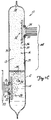
- Figure 2 is a cross sectional view of a thermal via in accordance with the present invention.
- Figure 3 is a cross sectional view of a condenser in accordance with the present invention.
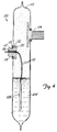
- Figure 4 is a cross sectional view of an alternative, two-phase thermal transfer apparatus in which the heat source is positioned within the bag and is submerged in a thermal transfer liquid.
- Figure 5 is a diagrammatic view of an alternative, thermal transfer apparatus having a condener positioned external to the bag, in accordance with the present invention.
- the present invention is a two-phase, flexible thermal transfer apparatus adapted for thermal connection to a heat source for conducting heat away from the heat source.
- Figures 1(a), 1(b), and 1(c) are cross sectional views of a two-phase, flexible thermal transfer apparatus 10 in communication with an external heat source 11 which is in various states of operation.
- Figure 1(a) illustrates thermal transfer apparatus 10 when heat source 11 is in a non-operating state.
- Figures 1(b) and 1(c) illustrate thermal transfer apparatus 10 when heat source 11 is in an operating state.
- Thermal transfer apparatus 10 expands or "puffs-up" with increasing heat flux from heat source 11 and with an increasing volume of liquid vapor 13, as shown in the progression through Figures 1(a) to 1(c).
- Heat source 11 can be any electronic device or heat generating component, such as an integrated circuit mounted on a circuit board 20.
- Thermal transfer apparatus 10 includes a flexible bag 12 containing a thermal transfer liquid 14.
- Flexible bag 12 is substantially impermeable to fluid and forms at least one expandable compartment 16.
- Compartment 16 is expandable between a first volume (Figure 1(a)) and a second volume ( Figure 1(c)) in response to changes in heat flux from heat source 11.
- Heat source 11 is positioned external to compartment 16 and is in thermal communication with the thermal transfer liquid 14.
- Thermal transfer apparatus 10 further includes a thermal via 22 and a condenser 24.
- Thermal via 22 extends through an aperture 26 in flexible bag 12 and has an extended heat dissipating surface 28.
- Thermal via 22 has a high thermal conductivity for conducting heat from heat source 11 to thermal transfer liquid 14.
- Thermal via 22 is optional in the present invention.
- flexible bag 12 is in direct contact with heat source 11 and conducts heat through its side walls.
- thermal via 22 is preferred since it provides greater heat flux from heat source 11 to the thermal transfer liquid 14.
- Condenser 24 extends through an aperture 30 in flexible bag 12 and has an extended condensing surface 32. Condenser 24 is also optional but is preferred since it assists in dissipating heat to the surrounding environment.
- Thermal transfer apparatus 10 operates as a two-phase heat sink since it uses both the liquid and gaseous forms of thermal transfer liquid 14.
- thermal transfer liquid 14 is compressed at ambient pressure and substantially fills the first volume of expandable compartment 16 such that expandable compartment 16 is essentially gas-free.
- a compressed liquid is a liquid that is below its boiling point at the existing pressure.
- Ambient pressure is the pressure of the environment in which thermal transfer apparatus 10 operates.
- Vapor level 38 defines a vapor reflux zone 44 where the vapor condenses and returns to liquid 14.
- Flexible bag 12 and condenser 24 conduct heat carried by the vapor to the exterior of the bag where the heat is dissipated to the external environment.
- Liquid 14 and the vapor maintain a liquid-vapor equilibrium at approximately ambient pressure within expandable compartment 16. Since bag 12 is flexible and has an expandable compartment, the liquid and vapor in the bag remain at approximately ambient pressure substantially independent of changes in heat flux from heat source 11. Therefore, the boiling point of thermal transfer liquid 14 remains substantially constant such that the operating temperature of heat source 11 does not rise significantly above the boiling point of the liquid with increasing heat flux from heat source 11.
- Thermal via 22 is shown in greater detail in Figure 2.
- Thermal via 22 has a first cylindrical portion 50 which extends through aperture 26 in a direction away from flexible bag 12 and liquid 14.
- the first portion 50 has a planar top 52 for direct, abutting contact with a flat external surface of heat source 11. Since bag 12 is flexible, thermal via 22 will self-shift due to internal pressures or weight of thermal transfer apparatus 10 until top 52 of thermal via 22 is in flat, planar contact with heat source 11.
- Thermal via 22 further includes a second cylindrical portion 54 which is remote from the first portion 50.
- Second portion 54 is connected to the first portion 50 and is located within flexible bag 12 such that the second portion 54 is submerged in thermal transfer liquid 14.
- Second portion 54 has an array of small stubs or fins 56 which provide the extended heat dissipating surface 28 for intimate contact and heat exchange with thermal transfer liquid 14. Fins 56 are optional.
- Thermal via 22 has an intermediate cylindrical portion 58 located between the first portion 50 and the second portion 54.
- Intermediate portion 58 is coaxial with portions 50 and 54 and has a cylindrical shape having a diameter larger than the diameter of the first portion 50 and smaller than the diameter of the second portion 54.
- An annular groove 60 is formed on intermediate portion 58, which receives an O-ring 62.
- An annular lock ring 64 together with O-ring 62, comprise a means for sealingly connecting thermal via 22 to flexible bag 12 in an area adjacent aperture 26.
- Lock ring 64 is flexible and has an inner diameter slightly smaller than the outer diameter of the first portion 50 in order to establish a self-sustaining, interference fit relationship when lock ring 64 is pressed over the first portion 50.
- lock ring 64 presses bag 12 against O-ring 62 in order to seal thermal via 22 to bag 12.
- lock ring 64 is made of a plastic material.
- Lock ring 64 includes threaded holes (not shown) for coupling lock ring 64 to a pressing tool for detaching the lock ring from thermal via 22 if maintenance or repair of apparatus 10 is desired.
- the second portion 54 of thermal via 22 has a larger surface area than the exposed external surface area of the first portion 50, such that the second portion 54 functions as a heat-radiating body to quickly dissipate thermal energy conducted from heat source 11.
- Intermediate portion 58, being of smaller diameter than the second portion 54 serves as a stand-off in order to space the second portion 54 away from flexible bag 12 and thereby enable thermal transfer liquid 14 to contact a top wall 66 of the second portion 54 as well as the extended heat dissipating surface 28.
- Thermal via 22 is made of a material, preferably aluminum, having a high thermal conductivity that may exceed the thermal conductivity of flexible bag 12.
- Thermal transfer apparatus 10 can also include multiple thermal vias, with each via being similar to via 22. With multiple vias, a single bag can be used to cool a number of electrical components, with each component simultaneously contacting a respective via.
- Thermal via 22 is described in greater detail in U.S. Patent No, 5,046,552 (Tousignant) and in U.S. Patent No. 5,000,256 (Tousignant).
- Flexible bag 12 can be made of a single or multi-layer plastic film.
- Thermal plastic films are preferred since they are readily available and many are heat sealable. If the film is of multi-layer construction, the layers or plies must be bonded so that they cannot be mechanically separated.
- the film can be chosen from the family of single or multi-layer films that have properties of durability, flexibility and low permeabilities to air and to the thermal transfer liquid 14. Multi-layer films are preferred because each film layer can contribute its best characteristics, like heat sealability or fluid impermeability, to the overall film characteristics while a particular film's weaknesses, such as low durability or air permeability, can be compensated for by other film layers.
- a representative range of film durability can be described by a tensile strength, M.D. Break (as measured per ASTM D882 Method A) of 2.69 kgf/cm, by an elongation, M.D. Break (as measured per ASTM D882 Method A) of about 100% by an Elmendorf tear strength (as measured per ASTM D1922) of 32-no tear gm/ply, and by a Mullen burst strength range (as measured per ASTM D744) of 2.8-3.5 kgf/cm2.
- a representative range of film air-permeability can be expressed as oxygen permeability (as measured per ASTM D3985) of 0.4-7.0 cc/100 in2/24hr, at 760 torr.
- a representative range of film permeability to thermally conductive liquid is 0-1 gram of bag weight lost after heating, per 100 grams of bag weight as measured before heating.
- Film permeability to thermally conductive liquid was measured by determining weight loss from a sealed bag filled with helium de-gassed FluorinertTM FCTM-77 liquid (available from 3M Company, Saint Paul, Minnesota, U.S.A.) after heating said bag in a horizontal position in an oven or like device held at 50° C., for 70 hours.
- the bag was 8.23 ⁇ 0.08 cm wide, and 12.06 ⁇ 0.08 cm long before filling with about 56 ml of FCTM-77 liquid.
- the liquid volume gave the sealed bag a thickness of 0.69 ⁇ 0.08 cm prior to heating the bag.
- FCTM-77 liquid for filling the bag, helium gas was bubbled or sparged through the liquid at a rate of 250 cc/min for 20 minutes, at normal ambient conditions. After heating the bag in the oven it was cooled to room temperature before weighing. The liquid can also be de-gassed by boiling the liquid prior to sealing the bag.
- Three-layer films are available from C & H Packaging Co., Merrill, Wis.
- One example of a three-layer film has a nominal 8.9 ⁇ 10 ⁇ 3 cm (3.5 mil) thickness, has a heat-sealable layer of polyethylene-co-vinyl acetate about 2 mils thick, laminated by adhesive to a layer of polyvinylidene chloride bonded to a layer of about 1 mil of polyamide.
- Pantry Pack No. 50 is another suitable film which is available from American National Can Company.
- the film includes a 0.48 mil layer of polyethylene terephthalate (PET) which is laminated by an adhesive to a 0.50 mil layer of aluminum foil.
- PET polyethylene terephthalate
- the layer of aluminum foil is laminated by an adhesive to a 3.0 mil layer of modified polypropylene.
- thermal transfer bag and the preferred methods of fabricating and filling the thermal transfer bag are described in greater detail in U.S. Patent No. 4,997,032 (Danielson et al.), which is hereby incorporated by reference.
- any suitable container may be used which has at least one flexible surface to allow for expansion and contraction of expandable compartment 16.
- the thermal transfer liquid 14 is preferably thermally conductive, chemically inert, essentially gas-tree, and thermally stable.
- Thermal transfer liquid 14 has a boiling point that is at or below the operating temperature of heat source 11 such that portions of the liquid adjacent the extended heat dissipating surface 28 of thermal via 22 will vaporize when conducting heat from heat source 11.
- the thermal transfer liquid can be selected from the representative class of fluorinated linear, branched or cyclic alkanes, ethers, tertiary amines, and aminoethers. and mixtures thereof.
- perfluorinated chemicals are used in this invention, though partially fluorinated chemicals can also be used.
- the perfluorinated chemicals can be straight chain, branched chain, cyclic, or a combination thereof such as alkylcycloaliphatic, and are saturated, that is, tree of ethylenic, acetylenic, and aromatic unsaturation.
- the skeletal chain can include catenary oxygen and/or trivalent nitrogen heteroatoms providing stable links between fluorocarbon groups and not interfering with the inert character of the compound.
- liquids examples include CFCl2CFCl2, C8F18, C8F17Br, C8F17Cl, C5F11OC6F13, (C4F9)3N, [(CF3)2NC2F4]2O, perfluorodecalin, C6F13C6H13, C3F7O[CF(CF3)CF2O] n C2F5, c-C8F16O, 1,3-c-C6F10-(COOCH3)2, CF3SO2N(C2H5)2, 1,3,-C6H4(CH3)(OSO2CF3), and C3F7COO-t-C4H9.
- fluorinertTM liquid FCTM-75 which is a mixture of C8F18 and c-C8F16O
- FluorinertTM liquid FCTM-77 which has a composition like FCTM-75 but has a broader boiling point range.
- Other commercially available fluorochemicals are those available from Montedison S.p.A as GALDENTM Perfluorinated Fluid described in the trade bulletin "GaldenTM Perfluorinated Fluids"; those from Daikin Industries, Ltd. as DemnumTM fluids described in product bulletin No. ECC-5c(003)YW issued January, 1987; those from Air Products Co, as MULTI-FLUORTM; those from ISC, Ltd.; and those from Ashai Glass Company.
- the thermal transfer liquid 14 is preferably essentially gas-free.
- One method of purging gas from liquid 14 prior to sealing the bag comprises heating the liquid in a vessel until the temperature of the liquid is sufficiently high to expel air from the liquid and holding the liquid at this temperature until the air is expelled from the liquid. While the liquid is still hot, the bag is filled, remaining gas bubbles are displaced from the bag, and the bag is sealed.
- Another method of expelling gas from the liquid comprises bubbling or sparging the liquid with a gas having low solubility in the liquid.
- gases having low solubilities in the thermal transfer liquid are hydrogen and preferably helium.
- Condenser 24 is shown in greater detail in Figure 3.
- Condenser 24 includes a first portion 72 which extends into expandable compartment 16 at least partially within vapor reflux zone 44 and above liquid level 35.
- the first portion 72 includes and array of small stubs or fins 74 which provide the extended condensing surface 32 for efficient heat exchange with the vapor within vapor reflux zone 44.
- Condenser 24 further includes a second portion 78 which extends outward from flexible bag 12 and is in thermal communication with the first portion 72.
- the second portion 78 includes a plurality of fins 80 which provide an extended heat dissipating surface 81 for condenser 24.
- Condenser 24 can be attached to bag 12 by any known means of attachment which sealably connects the condenser to the bag.
- Condenser 24 is attached to bag 12 in a similar manner as thermal via 22 is attached to bag 12.
- Condenser 24 includes an annular flange 82 having an annular groove 84 formed adjacent to bag 12. Groove 84 receives an O-ring 86.
- An annular lock ring 88, together with O-ring 86, comprise a means for sealingly connecting condenser 24 to bag 12 within aperture 30.
- Lock ring 88 has an inner diameter slightly smaller than the outer diameter of the second portion 78 in order to establish a self-sustaining, interference fit relationship when lock ring 88 is pressed over the second portion 78.
- lock ring 88 is made of a plastic material.
- Condenser 24 increases condensation and increases the rate at which heat is dissipated to the surrounding environment. As the vapor condenses on condensing surface 32, condenser 24 conducts heat from the first portion 72 to the second portion 78 where the heat is dissipated to the surrounding environment.
- the heat can be dissipated by natural or forced air convection or by liquid convection.
- Condenser 24 dissipates heat at a rate which is proportional to the heat flux from heat source 11. As mentioned above, condenser 24 is positioned such that condensing surface 32 is positioned at least partially within vapor reflux zone 44. As the heat flux from heat source 11 increases ( Figures 1(b) and 1(c)), vapor space 36 expands and vapor level 38 rises along condensing surface 32 which exposes more of condensing surface 32 to the vapor and increases the rate of condensation. As the temperature of condenser 24 increases, the rate of heat transfer into the surrounding air increases. Therefore, condenser 24 efficiently transfers heat into the surrounding environment in proportion to the heat flux from heat source 11 such that expandable compartment 16 operates with minimum volume.
- condenser 24 provides several advantages, it should be noted that condenser 24 is optional in thermal transfer apparatus 10 since the vapor also condenses on the interior surfaces of bag 12. In certain applications, condensation on the interior surfaces of bag 12 provides sufficient heat dissipation. In one embodiment (not shown), bag 12 includes one or more pleats or folds which allow greater expansion of expandable compartment 16 and provide additional surface area for condensation within compartment 16.
- FIG. 4 is a cross sectional view of an alternative, two-phase thermal transfer bag apparatus in which the heat source is positioned internal to the flexible bag and is submerged in the thermal transfer liquid.
- Thermal transfer apparatus 100 includes flexible bag 102, thermal transfer liquid 104 and condenser 106.
- Heat source 108 is positioned internal to bag 102 and is submerged in thermal transfer liquid 104.
- heat source 108 includes a circuit board with a plurality of heat generating components.
- Communication and power leads 110 extend from heat source 108 through an aperture or umbilicus 112 in bag 102.
- An aluminum plug 114 similar to thermal via 22 (shown in Figure 2) and condenser 24 (shown in Figure 3) is sealed to bag 102 within aperture 112.
- the aluminum plug 114 includes an aperture 116 to allow leads 110 to pass through the plug.
- Leads 110 can be sealed to aluminum plug 114 with quick setting epoxy.
- Aluminum plug 114 further includes an annular groove 120 which receives an O-ring 122.
- An annular lock ring 124, together with O-ring 122, comprise a means for sealingly attaching aluminum plug 114 to bag 102 in a similar manner as thermal via 22 (Figure 2) is attached to bag 12.
- Figure 4 illustrates a embodiment in which an aluminum plug is used to pass communication and power leads to and from heat source 108, any other method or apparatus for providing communication and power leads to heat source 108 can be used with the present invention.
- FIG. 5 is a diagrammatic view of an embodiment in which the thermal transfer apparatus of the present invention includes a remote condenser which is positioned external to the bag and the expandable compartment.
- Thermal transfer apparatus 150 includes heat source 152, thermal transfer bag 154 and remote condenser 156.
- Remote condenser 156 is connected to thermal transfer bag 154 through tubes 158 and 162.
- thermal transfer bag 154 conducts heat 163 from heat source 152 causing the thermal transfer liquid within bag 154 to vaporize and form a vapor within the bag.
- the vapor travels through tube 158 in a direction indicated by arrow 160 to remote condenser 156 where the vapor condenses and forms a condensate.
- the condensate returns to thermal transfer bag 154 through tube 158 or through optional return tube 162 in a direction indicated by arrow 164 for additional cooling of heat source 152.
- Thermal transfer apparatus 150 can further include a wick 166 extending between remote condenser 156 and the thermal transfer liquid to assist in returning the condensate to bag 154.
- Wick 166 allows greater flexibility in the design and use of thermal transfer apparatus 150 since gravity is no longer required to return the condensate to bag 154.
- the wick may be used in low gravity space applications or in applications that require various physical orientations of the bag and condenser. Without wick 166, thermal transfer apparatus 150 requires condenser 156 to be positioned above the thermal transfer liquid or requires a pump (not shown) between condenser 156 and the liquid such that the condensate will return to bag 154.
- the flexible, two-phase thermal transfer apparatus of the present invention is particularly useful as a heat sink for microelectronic components.
- the thermal transfer bag draws no additional power from the system and is efficient enough to cool high-power integrated circuits such as the PentiumTM microprocessor which is manufactured by Intel Corporation.
- the thermal transfer bag can simply be placed in the system housing, adjacent the integrated circuits that require cooling.
- the flexible nature of the bag allows the bag to conform to the interior of the housing and to act as a shock absorber for the integrated circuits.
- the bag provides a low-profile, efficient liquid cooling technique that can be used in smaller systems such as desktop and notebook computers.
- the flexible, two-phase thermal transfer apparatus of the present invention offers important advantages over the performance of a single phase system.
- the operating temperature of the heat source in a two-phase system is dependent on the boiling point of the liquid that is used as a heat transfer fluid. Provided the heat flux at the heat source does not exceed the critical heat flux of the liquid, and as long as the heat supplied to the liquid is removed, the heat source operates at a fairly uniform temperature. Further, the flexible nature of the bag allows the boiling point of the liquid to remain constant, which maintains the integrated circuits at a stable operating temperature. As heat flux from the integrated circuits increases, the volume of the bag increases to maintain ambient pressure within the bag and thus maintain a constant boiling point.
- An added benefit of a two-phase system is that the condenser dissipates heat more efficiently than a single phase system dissipates heat.
- the expandable compartment may be formed by a rigid container having at least one flexible surface or joint.
- the heat source can be positioned internal to the container, external to the container, or as part of the hermetic seal of the container.
- Various other changes can also be made without departing from the spirit and scope of the present invention.
Landscapes
- Engineering & Computer Science (AREA)
- Life Sciences & Earth Sciences (AREA)
- Sustainable Development (AREA)
- Physics & Mathematics (AREA)
- Thermal Sciences (AREA)
- Mechanical Engineering (AREA)
- General Engineering & Computer Science (AREA)
- Cooling Or The Like Of Electrical Apparatus (AREA)
- Cooling Or The Like Of Semiconductors Or Solid State Devices (AREA)
Applications Claiming Priority (2)
| Application Number | Priority Date | Filing Date | Title |
|---|---|---|---|
| US226272 | 1994-04-11 | ||
| US08/226,272 US5411077A (en) | 1994-04-11 | 1994-04-11 | Flexible thermal transfer apparatus for cooling electronic components |
Publications (1)
| Publication Number | Publication Date |
|---|---|
| EP0676804A1 true EP0676804A1 (de) | 1995-10-11 |
Family
ID=22848241
Family Applications (1)
| Application Number | Title | Priority Date | Filing Date |
|---|---|---|---|
| EP95105377A Withdrawn EP0676804A1 (de) | 1994-04-11 | 1995-04-10 | Wärmeableitungsvorrichtung zur Kühlung von elektronischen Bausteinen |
Country Status (7)
| Country | Link |
|---|---|
| US (1) | US5411077A (de) |
| EP (1) | EP0676804A1 (de) |
| JP (1) | JPH07318271A (de) |
| KR (1) | KR100336187B1 (de) |
| CA (1) | CA2144143A1 (de) |
| MY (1) | MY121913A (de) |
| TW (1) | TW280088B (de) |
Cited By (2)
| Publication number | Priority date | Publication date | Assignee | Title |
|---|---|---|---|---|
| RU2142660C1 (ru) * | 1996-10-04 | 1999-12-10 | Мордовский государственный университет им.Н.П.Огарева | Силовой полупроводниковый блок с испарительным охлаждением |
| CN107979948A (zh) * | 2017-11-08 | 2018-05-01 | 深圳市共进电子股份有限公司 | 散热系统及网络通讯设备 |
Families Citing this family (70)
| Publication number | Priority date | Publication date | Assignee | Title |
|---|---|---|---|---|
| US5768906A (en) * | 1996-01-16 | 1998-06-23 | Borst, Inc. | Electrochemical heat exchanger |
| US5642776A (en) * | 1996-02-27 | 1997-07-01 | Thermacore, Inc. | Electrically insulated envelope heat pipe |
| US5930117A (en) * | 1996-05-07 | 1999-07-27 | Sheldahl, Inc. | Heat sink structure comprising a microarray of thermal metal heat channels or vias in a polymeric or film layer |
| US5829515A (en) * | 1996-05-10 | 1998-11-03 | Dell U.S.A., L.P. | Heat dissipator with multiple thermal cooling paths |
| US5969944A (en) * | 1996-12-31 | 1999-10-19 | Intel Corporation | Method and apparatus for mounting a very large scale integration (VLSI) chip package to a computer chasis for cooling |
| US5978228A (en) * | 1996-12-31 | 1999-11-02 | Intel Corporation | Apparatus for mounting a very large scale integration (VLSI) chip to a computer chassis for cooling |
| US6137688A (en) | 1996-12-31 | 2000-10-24 | Intel Corporation | Apparatus for retrofit mounting a VLSI chip to a computer chassis for current supply |
| US6018465A (en) * | 1996-12-31 | 2000-01-25 | Intel Corporation | Apparatus for mounting a chip package to a chassis of a computer |
| US6019167A (en) * | 1997-12-19 | 2000-02-01 | Nortel Networks Corporation | Liquid immersion cooling apparatus for electronic systems operating in thermally uncontrolled environments |
| US6021844A (en) * | 1998-06-03 | 2000-02-08 | Batchelder; John Samuel | Heat exchange apparatus |
| US5940270A (en) * | 1998-07-08 | 1999-08-17 | Puckett; John Christopher | Two-phase constant-pressure closed-loop water cooling system for a heat producing device |
| JP3948642B2 (ja) * | 1998-08-21 | 2007-07-25 | 信越化学工業株式会社 | 熱伝導性グリース組成物及びそれを使用した半導体装置 |
| US6260613B1 (en) * | 1999-01-05 | 2001-07-17 | Intel Corporation | Transient cooling augmentation for electronic components |
| US6085831A (en) * | 1999-03-03 | 2000-07-11 | International Business Machines Corporation | Direct chip-cooling through liquid vaporization heat exchange |
| US6283201B1 (en) * | 2000-09-22 | 2001-09-04 | Sui Yung Lee | Heat-radiating structure |
| EP1202344A1 (de) * | 2000-10-09 | 2002-05-02 | Lee, Siu-yung | Wärmesenke |
| US20030080839A1 (en) * | 2001-10-31 | 2003-05-01 | Wong Marvin Glenn | Method for improving the power handling capacity of MEMS switches |
| US6820684B1 (en) * | 2003-06-26 | 2004-11-23 | International Business Machines Corporation | Cooling system and cooled electronics assembly employing partially liquid filled thermal spreader |
| US20050039888A1 (en) * | 2003-08-21 | 2005-02-24 | Pfahnl Andreas C. | Two-phase cooling apparatus and method for automatic test equipment |
| US20050094706A1 (en) * | 2003-10-30 | 2005-05-05 | International Business Machines Corporation | Transparent cooling duct |
| TWI235817B (en) * | 2004-03-26 | 2005-07-11 | Delta Electronics Inc | Heat-dissipating module |
| US20060088746A1 (en) * | 2004-10-25 | 2006-04-27 | 3M Innovative Properties Company | Passive dual-phase cooling for fuel cell assemblies |
| US20060090881A1 (en) * | 2004-10-29 | 2006-05-04 | 3M Innovative Properties Company | Immersion cooling apparatus |
| US7581585B2 (en) * | 2004-10-29 | 2009-09-01 | 3M Innovative Properties Company | Variable position cooling apparatus |
| JP2006261457A (ja) * | 2005-03-17 | 2006-09-28 | Fujitsu Ltd | 受熱体、受熱装置及び電子機器 |
| US20070034360A1 (en) * | 2005-06-08 | 2007-02-15 | Hall Jack P | High performance cooling assembly for electronics |
| US20070178255A1 (en) * | 2006-01-31 | 2007-08-02 | Farrow Timothy S | Apparatus, system, and method for thermal conduction interfacing |
| EP1892810B1 (de) * | 2006-08-25 | 2011-05-18 | Abb Research Ltd. | Kühleinrichtung für ein elektrisches Betriebsmittel |
| US20090287263A1 (en) * | 2008-05-14 | 2009-11-19 | Cardiac Pacemakers, Inc. | Medical device with liquid filled housing |
| TW201019431A (en) * | 2008-11-03 | 2010-05-16 | Wen-Qiang Zhou | Insulating and heat-dissipating structure of an electronic component |
| US8910706B2 (en) * | 2009-02-05 | 2014-12-16 | International Business Machines Corporation | Heat sink apparatus with extendable pin fins |
| US8215377B1 (en) * | 2009-05-06 | 2012-07-10 | Lockheed Martin Corporation | Heat transfer device with flexible cooling layer |
| US8490679B2 (en) * | 2009-06-25 | 2013-07-23 | International Business Machines Corporation | Condenser fin structures facilitating vapor condensation cooling of coolant |
| US8018720B2 (en) * | 2009-06-25 | 2011-09-13 | International Business Machines Corporation | Condenser structures with fin cavities facilitating vapor condensation cooling of coolant |
| US8059405B2 (en) * | 2009-06-25 | 2011-11-15 | International Business Machines Corporation | Condenser block structures with cavities facilitating vapor condensation cooling of coolant |
| US8014150B2 (en) * | 2009-06-25 | 2011-09-06 | International Business Machines Corporation | Cooled electronic module with pump-enhanced, dielectric fluid immersion-cooling |
| AU2010300549B2 (en) | 2009-09-30 | 2014-09-11 | Ge Healthcare Bio-Sciences Corp | Disposable bioreactor condenser bag and filter heater |
| US8455242B2 (en) * | 2010-02-22 | 2013-06-04 | Hyclone Laboratories, Inc. | Mixing system with condenser |
| JPWO2011145618A1 (ja) * | 2010-05-19 | 2013-07-22 | 日本電気株式会社 | 沸騰冷却器 |
| US8619425B2 (en) * | 2011-10-26 | 2013-12-31 | International Business Machines Corporation | Multi-fluid, two-phase immersion-cooling of electronic component(s) |
| EP2848101B1 (de) | 2012-05-07 | 2019-04-10 | Phononic Devices, Inc. | Thermoelektrische wärmetauscherkomponente mit wärmeverteilungsschutzklappe und optimalem thermischem grenzflächenwiderstand |
| US20130291555A1 (en) | 2012-05-07 | 2013-11-07 | Phononic Devices, Inc. | Thermoelectric refrigeration system control scheme for high efficiency performance |
| US11788797B2 (en) | 2012-07-18 | 2023-10-17 | University Of Virginia Patent Foundation | Heat transfer device for high heat flux applications and related methods thereof |
| US10217692B2 (en) | 2012-07-18 | 2019-02-26 | University Of Virginia Patent Foundation | Heat transfer device for high heat flux applications and related methods thereof |
| JP5782496B2 (ja) * | 2013-11-07 | 2015-09-24 | 山崎産業株式会社 | 袋入り液体冷却装置及び冷却体 |
| BR122022000294B1 (pt) | 2014-03-21 | 2022-08-16 | Life Technologies Corporation | Montagem de filtragem e método para filtrar um gás |
| JP6585615B2 (ja) | 2014-03-21 | 2019-10-02 | ライフ テクノロジーズ コーポレイション | 流体処理システムのための凝縮器システム |
| US9593871B2 (en) | 2014-07-21 | 2017-03-14 | Phononic Devices, Inc. | Systems and methods for operating a thermoelectric module to increase efficiency |
| US10458683B2 (en) | 2014-07-21 | 2019-10-29 | Phononic, Inc. | Systems and methods for mitigating heat rejection limitations of a thermoelectric module |
| US9457306B2 (en) | 2014-10-07 | 2016-10-04 | Life Technologies Corporation | Regulated vacuum off-gassing of gas filter for fluid processing system and related methods |
| US20170321966A1 (en) * | 2014-12-03 | 2017-11-09 | Ge Intelligent Platforms, Inc. | Combined energy dissipation apparatus and method |
| JP6548032B2 (ja) * | 2015-03-19 | 2019-07-24 | 株式会社オートネットワーク技術研究所 | 冷却部材、及び蓄電モジュール |
| CN106155183B (zh) * | 2015-03-30 | 2019-07-19 | 研华股份有限公司 | 动态压力模块及其制造方法 |
| DE112016004166B4 (de) * | 2015-09-14 | 2024-01-18 | Mitsubishi Electric Corporation | Kühlvorrichtung, energieumwandlungs-vorrichtung und kühlsystem |
| WO2017116910A1 (en) | 2015-12-29 | 2017-07-06 | Life Technologies Corporation | Flexible bioprocessing container with partial dividing partition |
| KR20170092982A (ko) * | 2016-02-04 | 2017-08-14 | 삼성전자주식회사 | 배터리 열관리 장치 및 방법 |
| US10934936B2 (en) * | 2017-07-10 | 2021-03-02 | Rolls-Royce North American Technologies, Inc. | Cooling system in a hybrid electric propulsion gas turbine engine for cooling electrical components therein |
| CN109862751B (zh) * | 2019-02-22 | 2020-03-31 | 保定市龙跃电力器材制造有限公司 | 一种无功功率补偿箱 |
| TWM589293U (zh) * | 2019-08-23 | 2020-01-11 | 緯創資通股份有限公司 | 散熱模組與電子裝置 |
| US11178789B2 (en) * | 2020-03-31 | 2021-11-16 | Advanced Energy Industries, Inc. | Combination air-water cooling device |
| US12185511B2 (en) * | 2020-12-16 | 2024-12-31 | Toyota Motor Engineering & Manufacturing North America, Inc. | Power electronics systems comprising a two-phase cold plate housing a vaporization structure |
| GB2605974B (en) * | 2021-04-19 | 2023-05-24 | Katrick Tech Limited | Cooling apparatus, system and method of manufacture |
| WO2023133379A2 (en) | 2022-01-04 | 2023-07-13 | Bluexthermal, Inc. | Ocular region heat transfer devices and associated systems and methods |
| JP7476913B2 (ja) * | 2022-02-01 | 2024-05-01 | 株式会社豊田中央研究所 | ポンプ、ヒートパイプ |
| JP2023180925A (ja) * | 2022-06-10 | 2023-12-21 | レノボ・シンガポール・プライベート・リミテッド | ベーパーチャンバ及び電子機器 |
| WO2024209564A1 (ja) * | 2023-04-04 | 2024-10-10 | 株式会社Zyrq | 電子機器の冷却システム、及び冷却方法 |
| WO2024209558A1 (ja) * | 2023-04-04 | 2024-10-10 | 株式会社Zyrq | 電子機器の冷却システム、及び冷却方法 |
| WO2025069225A1 (ja) * | 2023-09-26 | 2025-04-03 | 株式会社Zyrq | 電子機器の冷却システム、および冷却方法 |
| WO2025099953A1 (ja) * | 2023-11-11 | 2025-05-15 | 株式会社Zyrq | 電子機器の冷却システム、および冷却方法 |
| DE102023212844A1 (de) * | 2023-12-18 | 2025-06-18 | Zf Friedrichshafen Ag | Kühlvorrichtung sowie Steuergerät mit einer solchen Kühlvorrichtung |
Citations (8)
| Publication number | Priority date | Publication date | Assignee | Title |
|---|---|---|---|---|
| US3741292A (en) * | 1971-06-30 | 1973-06-26 | Ibm | Liquid encapsulated air cooled module |
| US4092697A (en) * | 1976-12-06 | 1978-05-30 | International Business Machines Corporation | Heat transfer mechanism for integrated circuit package |
| US4155402A (en) * | 1977-01-03 | 1979-05-22 | Sperry Rand Corporation | Compliant mat cooling |
| US4563375A (en) * | 1982-12-16 | 1986-01-07 | Hasler Ag | Flat bag filled with thermally conducting liquid or paste |
| WO1986005942A1 (en) * | 1985-03-26 | 1986-10-09 | Hughes Aircraft Company | Electronic module with self-activated heat pipe |
| US4997032A (en) * | 1987-09-25 | 1991-03-05 | Minnesota Mining And Manufacturing Company | Thermal transfer bag |
| US5000256A (en) * | 1990-07-20 | 1991-03-19 | Minnesota Mining And Manufacturing Company | Heat transfer bag with thermal via |
| US5046552A (en) * | 1990-07-20 | 1991-09-10 | Minnesota Mining And Manufacturing | Flow-through heat transfer apparatus with movable thermal via |
Family Cites Families (13)
| Publication number | Priority date | Publication date | Assignee | Title |
|---|---|---|---|---|
| US3256703A (en) * | 1965-03-22 | 1966-06-21 | North American Aviation Inc | Compact liquid heat exchanger |
| US3496995A (en) * | 1967-06-23 | 1970-02-24 | Sanders Associates Inc | Furlable heat exchanger |
| US3826957A (en) * | 1973-07-02 | 1974-07-30 | Gen Electric | Double-sided heat-pipe cooled power semiconductor device assembly using compression rods |
| US4072188A (en) * | 1975-07-02 | 1978-02-07 | Honeywell Information Systems Inc. | Fluid cooling systems for electronic systems |
| DE2841051A1 (de) * | 1978-09-21 | 1980-04-03 | Daimler Benz Ag | Waermeuebertragung nach dem prinzip des waermerohres |
| US4381032A (en) * | 1981-04-23 | 1983-04-26 | Cutchaw John M | Apparatus for cooling high-density integrated circuit packages |
| US4646815A (en) * | 1983-12-23 | 1987-03-03 | Matsushita Electric Works, Ltd. | Heat exchange mat |
| JPS6118159A (ja) * | 1984-07-04 | 1986-01-27 | Hitachi Ltd | 半導体装置 |
| US4938279A (en) * | 1988-02-05 | 1990-07-03 | Hughes Aircraft Company | Flexible membrane heat sink |
| US4951740A (en) * | 1988-06-27 | 1990-08-28 | Texas A & M University System | Bellows heat pipe for thermal control of electronic components |
| US5205348A (en) * | 1991-05-31 | 1993-04-27 | Minnesota Mining And Manufacturing Company | Semi-rigid heat transfer devices |
| US5168921A (en) * | 1991-12-23 | 1992-12-08 | Thermacore, Inc. | Cooling plate with internal expandable heat pipe |
| US5249358A (en) * | 1992-04-28 | 1993-10-05 | Minnesota Mining And Manufacturing Company | Jet impingment plate and method of making |
-
1994
- 1994-04-11 US US08/226,272 patent/US5411077A/en not_active Expired - Fee Related
-
1995
- 1995-03-01 TW TW084101904A patent/TW280088B/zh active
- 1995-03-07 CA CA002144143A patent/CA2144143A1/en not_active Abandoned
- 1995-03-28 KR KR1019950006693A patent/KR100336187B1/ko not_active Expired - Fee Related
- 1995-03-31 MY MYPI95000832A patent/MY121913A/en unknown
- 1995-04-05 JP JP7080314A patent/JPH07318271A/ja active Pending
- 1995-04-10 EP EP95105377A patent/EP0676804A1/de not_active Withdrawn
Patent Citations (8)
| Publication number | Priority date | Publication date | Assignee | Title |
|---|---|---|---|---|
| US3741292A (en) * | 1971-06-30 | 1973-06-26 | Ibm | Liquid encapsulated air cooled module |
| US4092697A (en) * | 1976-12-06 | 1978-05-30 | International Business Machines Corporation | Heat transfer mechanism for integrated circuit package |
| US4155402A (en) * | 1977-01-03 | 1979-05-22 | Sperry Rand Corporation | Compliant mat cooling |
| US4563375A (en) * | 1982-12-16 | 1986-01-07 | Hasler Ag | Flat bag filled with thermally conducting liquid or paste |
| WO1986005942A1 (en) * | 1985-03-26 | 1986-10-09 | Hughes Aircraft Company | Electronic module with self-activated heat pipe |
| US4997032A (en) * | 1987-09-25 | 1991-03-05 | Minnesota Mining And Manufacturing Company | Thermal transfer bag |
| US5000256A (en) * | 1990-07-20 | 1991-03-19 | Minnesota Mining And Manufacturing Company | Heat transfer bag with thermal via |
| US5046552A (en) * | 1990-07-20 | 1991-09-10 | Minnesota Mining And Manufacturing | Flow-through heat transfer apparatus with movable thermal via |
Non-Patent Citations (1)
| Title |
|---|
| H.B. PARSAPOUR: "Convection cooling in small terminals", IBM TECHNICAL DISCLOSURE BULLETIN, vol. 24, no. 2, NEW YORK, US, pages 1222 * |
Cited By (2)
| Publication number | Priority date | Publication date | Assignee | Title |
|---|---|---|---|---|
| RU2142660C1 (ru) * | 1996-10-04 | 1999-12-10 | Мордовский государственный университет им.Н.П.Огарева | Силовой полупроводниковый блок с испарительным охлаждением |
| CN107979948A (zh) * | 2017-11-08 | 2018-05-01 | 深圳市共进电子股份有限公司 | 散热系统及网络通讯设备 |
Also Published As
| Publication number | Publication date |
|---|---|
| CA2144143A1 (en) | 1995-10-12 |
| KR100336187B1 (ko) | 2002-09-05 |
| TW280088B (de) | 1996-07-01 |
| US5411077A (en) | 1995-05-02 |
| JPH07318271A (ja) | 1995-12-08 |
| MY121913A (en) | 2006-03-31 |
Similar Documents
| Publication | Publication Date | Title |
|---|---|---|
| US5411077A (en) | Flexible thermal transfer apparatus for cooling electronic components | |
| US5720338A (en) | Two-phase thermal bag component cooler | |
| US5704416A (en) | Two phase component cooler | |
| US4997032A (en) | Thermal transfer bag | |
| US5458189A (en) | Two-phase component cooler | |
| WO1995026125A9 (en) | Two-phase thermal bag component | |
| US5000256A (en) | Heat transfer bag with thermal via | |
| US5412535A (en) | Apparatus and method for cooling electronic devices | |
| JP4309215B2 (ja) | 回路装置冷却装置 | |
| US6256201B1 (en) | Plate type heat pipe method of manufacturing same and cooling apparatus using plate type heat pipe | |
| US7013955B2 (en) | Flexible loop thermosyphon | |
| CN1969382B (zh) | 带有增强的沸腾/冷凝结构的热耗散设备 | |
| US5343940A (en) | Flexible heat transfer device | |
| EP0309279B1 (de) | Wärmeleitfähiger Beutel | |
| US20050111188A1 (en) | Thermal management device for an integrated circuit | |
| US20050088823A1 (en) | Variable density graphite foam heat sink | |
| JP2001165584A (ja) | シート状ヒートパイプ | |
| US20070097640A1 (en) | Liquid cooling device | |
| CN101053289A (zh) | 可变位置冷却设备 | |
| WO2018179162A1 (ja) | 冷却装置 | |
| US20240298426A1 (en) | Device for Dissipating Heat From Electronic Components in an Electronics Housing | |
| WO1996037366A1 (en) | Enclosure material for two-phase component cooler | |
| JP2001055564A (ja) | ヒートパイプ用作動液およびヒートパイプ |
Legal Events
| Date | Code | Title | Description |
|---|---|---|---|
| PUAI | Public reference made under article 153(3) epc to a published international application that has entered the european phase |
Free format text: ORIGINAL CODE: 0009012 |
|
| AK | Designated contracting states |
Kind code of ref document: A1 Designated state(s): DE FR GB IT NL |
|
| 17P | Request for examination filed |
Effective date: 19960404 |
|
| 17Q | First examination report despatched |
Effective date: 19971008 |
|
| GRAG | Despatch of communication of intention to grant |
Free format text: ORIGINAL CODE: EPIDOS AGRA |
|
| GRAG | Despatch of communication of intention to grant |
Free format text: ORIGINAL CODE: EPIDOS AGRA |
|
| GRAG | Despatch of communication of intention to grant |
Free format text: ORIGINAL CODE: EPIDOS AGRA |
|
| GRAH | Despatch of communication of intention to grant a patent |
Free format text: ORIGINAL CODE: EPIDOS IGRA |
|
| STAA | Information on the status of an ep patent application or granted ep patent |
Free format text: STATUS: THE APPLICATION IS DEEMED TO BE WITHDRAWN |
|
| 18D | Application deemed to be withdrawn |
Effective date: 20020508 |