EP0677428B1 - Support d'un rétroviseur interne d'un véhicule automobile - Google Patents
Support d'un rétroviseur interne d'un véhicule automobile Download PDFInfo
- Publication number
- EP0677428B1 EP0677428B1 EP95104265A EP95104265A EP0677428B1 EP 0677428 B1 EP0677428 B1 EP 0677428B1 EP 95104265 A EP95104265 A EP 95104265A EP 95104265 A EP95104265 A EP 95104265A EP 0677428 B1 EP0677428 B1 EP 0677428B1
- Authority
- EP
- European Patent Office
- Prior art keywords
- mirror
- transmitting
- receiving unit
- transmitter
- mirror mounting
- Prior art date
- Legal status (The legal status is an assumption and is not a legal conclusion. Google has not performed a legal analysis and makes no representation as to the accuracy of the status listed.)
- Expired - Lifetime
Links
- 238000005192 partition Methods 0.000 claims description 3
- 230000005540 biological transmission Effects 0.000 description 6
- 238000009434 installation Methods 0.000 description 2
- 230000004308 accommodation Effects 0.000 description 1
- 238000004026 adhesive bonding Methods 0.000 description 1
- 230000005855 radiation Effects 0.000 description 1
- 238000002604 ultrasonography Methods 0.000 description 1
Images
Classifications
-
- H—ELECTRICITY
- H04—ELECTRIC COMMUNICATION TECHNIQUE
- H04B—TRANSMISSION
- H04B1/00—Details of transmission systems, not covered by a single one of groups H04B3/00 - H04B13/00; Details of transmission systems not characterised by the medium used for transmission
- H04B1/38—Transceivers, i.e. devices in which transmitter and receiver form a structural unit and in which at least one part is used for functions of transmitting and receiving
- H04B1/3822—Transceivers, i.e. devices in which transmitter and receiver form a structural unit and in which at least one part is used for functions of transmitting and receiving specially adapted for use in vehicles
-
- B—PERFORMING OPERATIONS; TRANSPORTING
- B60—VEHICLES IN GENERAL
- B60R—VEHICLES, VEHICLE FITTINGS, OR VEHICLE PARTS, NOT OTHERWISE PROVIDED FOR
- B60R1/00—Optical viewing arrangements; Real-time viewing arrangements for drivers or passengers using optical image capturing systems, e.g. cameras or video systems specially adapted for use in or on vehicles
- B60R1/12—Mirror assemblies combined with other articles, e.g. clocks
- B60R2001/1284—Mirror assemblies combined with other articles, e.g. clocks with communication systems other than radio-receivers, e.g. keyless entry systems, navigation systems; with anti-collision systems
Definitions
- the invention relates to a mirror holder for an interior rear view mirror of a motor vehicle according to the preamble of the claim 1.
- Traffic control systems are already in use to help the driver allow a motor vehicle its current position for example recognizable within a city or to a desired one Street or the like.
- the transmitter / receiver unit is on the windshield glued to the motor vehicle.
- the electrical lines for the Transmitter / receiver units must also be on the windshield be attached. This is with a lot of effort connected.
- the invention has for its object a mirror holder of this type so that an optimal functionality of the Transmitter / receiver unit with a small footprint and simple design Design is guaranteed.
- the inventive design of the recording can Transmit signals from the transmitter / receiver unit unhindered enter.
- the inventive design of the recording can Transmitter and receiver in separate rooms, reducing the transmission signals are not affected by the received signals can. This ensures an optimal transmission and reception quality ensures that information from the traffic control system is flawless can be passed on to the driver.
- the sending / receiving unit is housed in the mirror holder, so that additional space for the transmitter / receiver unit is not required becomes. There is also a special constructive design of the unit and / or the mirror mount is not required.
- the transmitting / receiving unit an IR transmitter / receiver unit.
- the transmitter / receiver unit also with other signals, for example work with ultrasound. Basically any suitable one Training possible.
- the mirror holder is included provided at least one receptacle in the at least one transmitting / receiving unit an electronic toll system is.
- This toll system is to be used on motorways, around the freeway tolls for everyone using the freeway Determine motor vehicle.
- the send / receive units required for this can easily be accommodated in the mirror holder and sheltered.
- the mirror holder both with the transmitter / receiver unit for the traffic control system as well as the transmitter / receiver unit for the toll system. Both transmitter / receiver units are advantageously in one Accommodation of the mirror holder housed.
- the transmitter / receiver unit for the electronic toll system is connected to the vehicle battery for power supply.
- the mirror holder according to the invention advantageously has a housing in which the recording for the transmitter / receiver unit located.
- This housing is advantageous with the base of the mirror holder connected, preferably integrally formed with it. Thereby can the mirror holder together with the housing in one Work step can be manufactured and assembled. It is not necessary, to mount the housing separately.
- the housing is over a Intermediate piece connected to the foot.
- the intermediate piece can do so be formed that the housing and the one located therein Transmitter / receiver unit at a suitable one for its function Place on the windshield of the motor vehicle.
- a bracket protrudes from the foot on which the interior rear-view mirror is arranged is.
- the transmitter / receiver unit in the housing has a cover. It is designed so that the transmission / reception signals of the transmission / reception unit by the Cover can pass through unhindered.
- the cover is advantageously detachably connected to the housing.
- the cover is advantageously detachably connected to the housing.
- the circuit board is advantageously also accommodated in the receptacle, on which the transmitter and the receiver of the transmitter / receiver unit to sit.
- the invention is illustrated by one in the drawing Embodiment explained in more detail.
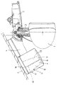
- the Drawing shows partly in side view and partly on average an interior rear view mirror according to the invention.
- the interior rearview mirror 1 is known with a foot 2 Way on the inside of the roof of a motor vehicle attached. From the mirror base 2 stands down a carrier 3 from which the inside rear view mirror 1 is attached is. The foot 2 extends in the direction of travel of the vehicle forwards and backwards over the carrier 3. The part of the foot 2 projecting forward is an intermediate piece 4 that on the inside of a windshield 5 of the motor vehicle is present.
- the intermediate piece 4 connects a housing 6 to the foot 2.
- the housing 6 can be attached to adapter 4 by gluing, locking, screwing, Be stuck or the like. It is also possible, to form the housing 6 in one piece with the intermediate piece 4.
- An infrared transmitter 7 is accommodated in the housing 6, who sits on a circuit board 8. On her also sits an infrared receiver 9, with the in still signals to be described can be received. To impair the IR receiver 9 by the Avoid transmitter 7 is one between the two components Partition 10 provided.
- the transmitter 7 and the receiver 9 are located in a recording room 11 inside the housing 6. This recording space 11 is advantageous in the direction of the windshield 5 extended training.
- the Housing 6 has a cover 14, which is preferably detachable is connected to the housing 6. This is the electronics within the housing 6 easily accessible and can be repaired or replaced if necessary.
- the Cover 14 is for the infrared radiation emitted by transmitter 7 permeable, so that the receiver 9 receives the corresponding infrared signals.
- the transmitter 7 and the receiver 9 form the motor vehicle side Part of a traffic management system with which it is possible corresponding to the motor vehicle or the driver Information while driving or at To bring the motor vehicle to a standstill.
- Traffic control systems are known and are therefore not explained in detail. These traffic control systems rely on that, for example, within a city Markers are provided which are aimed by the transmitter 7 can be. The reflected infrared signals are caught by the receiver 9, whereby the device 7, 9 receives information about where the motor vehicle is located within the urban area.
- the electronics, the transmitter 7 and the receiver 9 within of the housing 6 are housed and this housing Is part of the mirror mount, they must Parts not separately housed in the motor vehicle will.
- the intermediate piece 4 and Foot 2 is the electrical connections to the circuit board 8 simply lay inside the motor vehicle.
- Deviating from the illustrated embodiment can the circuit board 8, the transmitter 7 and the receiver 9 also housed in the intermediate piece 4 of the mirror holder be. In this case, the housing 6 is not necessary.
- An electronic can also be placed in the mirror holder Facility to be associated with an intended toll system is to be used.
- the appropriate facility with which the vehicle over the toll system can be recognized is also advantageous housed in the housing 6 of the mirror holder.
- this facility can also be provided in the intermediate piece 4.
- This facility can also be used together with the traffic control system be provided. Both facilities can housed in the housing 6 or in the intermediate piece 4 be. It is also possible to set up a facility in the housing 6 and the other device in the intermediate piece 4 to arrange. Because the mirror mount anyway is present in the motor vehicle, an additional Installation space for the facility is not required. In addition can be the corresponding via the mirror holder simply lay electrical leads in the motor vehicle.
Landscapes
- Engineering & Computer Science (AREA)
- Multimedia (AREA)
- Mechanical Engineering (AREA)
- Computer Networks & Wireless Communication (AREA)
- Signal Processing (AREA)
- Rear-View Mirror Devices That Are Mounted On The Exterior Of The Vehicle (AREA)
- Fittings On The Vehicle Exterior For Carrying Loads, And Devices For Holding Or Mounting Articles (AREA)
Claims (9)
- Support pour un rétroviseur interne (1) d'un véhicule automobile, comportant un pied (2) qui est relié au rétroviseur interne (1), et au moins une unité émettrice/réceptrice (7, 9) d'un système de guidage de circulation, caractérisé en ce que l'unité émettrice/réceptrice (7, 9) est logée dans une réception (11) prévue dans le support de rétroviseur, qui est subdivisée par une paroi intermédiaire (10) en une chambre de réception (12) pour un émetteur (7) et en une autre chambre de réception (13) pour un récepteur (9) de l'unité émettrice/réceptrice (7, 9).
- Support de rétroviseur selon la revendication 1, caractérisé en ce que l'unité émettrice/réceptrice (7, 9) est une unité émettrice/réceptrice à infrarouge.
- Support de rétroviseur selon l'une ou l'autre des revendications 1 et 2, caractérisé en ce que le support de rétroviseur présente au moins une réception (11) pour au moins une unité émettrice/réceptrice d'un système de péage électronique.
- Support de rétroviseur selon la revendication 3, caractérisé en ce que l'unité émettrice/réceptrice du système de guidage de circulation et du système de péage sont logées dans une réception commune.
- Support de rétroviseur selon l'une quelconque des revendications 1 à 4, caractérisé en ce que la réception (11) est prévue dans un boítier (6) du support de rétroviseur, lequel est relié au pied (2) de préférence au moyen d'une pièce intermédiaire (4).
- Support de rétroviseur selon l'une quelconque des revendications 1 à 5, caractérisé en ce que depuis le pied (2) dépasse un support (3) sur lequel est agencé le rétroviseur interne (1).
- Support de rétroviseur selon l'une ou l'autre des revendications 5 et 6, caractérisé en ce que le boítier (6) est pourvu d'un recouvrement (14) agencé de préférence de façon détachable, à travers lequel passent les signaux d'émission/réception de l'unité émettrice/réceptrice (7, 9).
- Support de rétroviseur selon l'une quelconque des revendications 1 à 7, caractérisé en ce que dans la réception (11) est logée une carte imprimée (8) sur laquelle reposent l'émetteur (7) et le récepteur (9) de l'unité émettrice/réceptrice (7, 9).
- Support de rétroviseur selon l'une quelconque des revendications 1 à 8, caractérisé en ce que la réception (11) est réalisée avec un élargissement en direction d'émission de l'unité émettrice/réceptrice (7, 9).
Applications Claiming Priority (2)
| Application Number | Priority Date | Filing Date | Title |
|---|---|---|---|
| DE9406204U DE9406204U1 (de) | 1994-04-14 | 1994-04-14 | Spiegelhalterung für einen Innenrückblickspiegel eines Kraftfahrzeuges |
| DE9406204U | 1994-04-14 |
Publications (2)
| Publication Number | Publication Date |
|---|---|
| EP0677428A1 EP0677428A1 (fr) | 1995-10-18 |
| EP0677428B1 true EP0677428B1 (fr) | 1998-06-10 |
Family
ID=6907322
Family Applications (1)
| Application Number | Title | Priority Date | Filing Date |
|---|---|---|---|
| EP95104265A Expired - Lifetime EP0677428B1 (fr) | 1994-04-14 | 1995-03-23 | Support d'un rétroviseur interne d'un véhicule automobile |
Country Status (3)
| Country | Link |
|---|---|
| EP (1) | EP0677428B1 (fr) |
| DE (2) | DE9406204U1 (fr) |
| ES (1) | ES2116639T3 (fr) |
Cited By (14)
| Publication number | Priority date | Publication date | Assignee | Title |
|---|---|---|---|---|
| US8710969B2 (en) | 2004-08-18 | 2014-04-29 | Magna Electronics Inc. | Accessory system for vehicle |
| US8749367B2 (en) | 1999-11-04 | 2014-06-10 | Magna Electronics Inc. | Driver assistance system for a vehicle |
| US8818042B2 (en) | 2004-04-15 | 2014-08-26 | Magna Electronics Inc. | Driver assistance system for vehicle |
| US8842176B2 (en) | 1996-05-22 | 2014-09-23 | Donnelly Corporation | Automatic vehicle exterior light control |
| US8917169B2 (en) | 1993-02-26 | 2014-12-23 | Magna Electronics Inc. | Vehicular vision system |
| US8926151B2 (en) | 1997-08-25 | 2015-01-06 | Magna Electronics Inc. | Vehicular accessory system |
| US8993951B2 (en) | 1996-03-25 | 2015-03-31 | Magna Electronics Inc. | Driver assistance system for a vehicle |
| US9035233B2 (en) | 1997-08-25 | 2015-05-19 | Magna Electronics Inc. | Accessory mounting system for mounting an electronic device at a windshield of a vehicle |
| US9090213B2 (en) | 2004-12-15 | 2015-07-28 | Magna Electronics Inc. | Accessory mounting system for a vehicle |
| US9233645B2 (en) | 1999-11-04 | 2016-01-12 | Magna Electronics Inc. | Accessory mounting system for a vehicle |
| US9283900B2 (en) | 1999-08-25 | 2016-03-15 | Magna Electronics Inc. | Accessory mounting system for a vehicle |
| US9436880B2 (en) | 1999-08-12 | 2016-09-06 | Magna Electronics Inc. | Vehicle vision system |
| US9434314B2 (en) | 1998-04-08 | 2016-09-06 | Donnelly Corporation | Electronic accessory system for a vehicle |
| US9555803B2 (en) | 2002-05-03 | 2017-01-31 | Magna Electronics Inc. | Driver assistance system for vehicle |
Families Citing this family (6)
| Publication number | Priority date | Publication date | Assignee | Title |
|---|---|---|---|---|
| DE19602578A1 (de) * | 1996-01-25 | 1997-07-31 | Mekra Lang Gmbh & Co Kg | Außenrückblickspiegel für Kraftfahrzeuge, insbesondere Nutzfahrzeuge |
| US5798882A (en) * | 1996-03-22 | 1998-08-25 | Sabine Lang | Rear-view mirror assembly with internal antenna mount |
| DE29713582U1 (de) * | 1997-07-31 | 1997-10-02 | Leopold Kostal GmbH & Co KG, 58507 Lüdenscheid | Kraftfahrzeug mit einem oder mit mehreren Systemen zum Verarbeiten von Informationen |
| US6824281B2 (en) | 2002-01-31 | 2004-11-30 | Donnelly Corporation | Vehicle accessory module |
| WO2008024639A2 (fr) | 2006-08-11 | 2008-02-28 | Donnelly Corporation | Système de commande automatique de phare de véhicule |
| CN109131094A (zh) * | 2018-10-08 | 2019-01-04 | 潘陈斐 | 一种可快速拆卸安装的汽车反光镜座装置 |
Family Cites Families (3)
| Publication number | Priority date | Publication date | Assignee | Title |
|---|---|---|---|---|
| US4930742A (en) * | 1988-03-25 | 1990-06-05 | Donnelly Corporation | Rearview mirror and accessory mount for vehicles |
| DE69332432T2 (de) * | 1992-06-25 | 2003-07-17 | Denso Corp | Gerät zur identification von beweglichen objekten |
| DE4322937A1 (de) * | 1993-07-09 | 1995-01-12 | Hohe Kg | Informationseinrichtung in einem Kraftfahrzeug |
-
1994
- 1994-04-14 DE DE9406204U patent/DE9406204U1/de not_active Expired - Lifetime
-
1995
- 1995-03-23 ES ES95104265T patent/ES2116639T3/es not_active Expired - Lifetime
- 1995-03-23 EP EP95104265A patent/EP0677428B1/fr not_active Expired - Lifetime
- 1995-03-23 DE DE59502456T patent/DE59502456D1/de not_active Expired - Fee Related
Cited By (24)
| Publication number | Priority date | Publication date | Assignee | Title |
|---|---|---|---|---|
| US8917169B2 (en) | 1993-02-26 | 2014-12-23 | Magna Electronics Inc. | Vehicular vision system |
| US8993951B2 (en) | 1996-03-25 | 2015-03-31 | Magna Electronics Inc. | Driver assistance system for a vehicle |
| US8842176B2 (en) | 1996-05-22 | 2014-09-23 | Donnelly Corporation | Automatic vehicle exterior light control |
| US9035233B2 (en) | 1997-08-25 | 2015-05-19 | Magna Electronics Inc. | Accessory mounting system for mounting an electronic device at a windshield of a vehicle |
| US8926151B2 (en) | 1997-08-25 | 2015-01-06 | Magna Electronics Inc. | Vehicular accessory system |
| US9527445B2 (en) | 1998-01-07 | 2016-12-27 | Magna Electronics Inc. | Accessory mounting system for mounting an accessory at a vehicle such that a camera views through the vehicle windshield |
| US9434314B2 (en) | 1998-04-08 | 2016-09-06 | Donnelly Corporation | Electronic accessory system for a vehicle |
| US9436880B2 (en) | 1999-08-12 | 2016-09-06 | Magna Electronics Inc. | Vehicle vision system |
| US9446715B2 (en) | 1999-08-25 | 2016-09-20 | Magna Electronics Inc. | Vision system for a vehicle |
| US9283900B2 (en) | 1999-08-25 | 2016-03-15 | Magna Electronics Inc. | Accessory mounting system for a vehicle |
| US9539956B2 (en) | 1999-08-25 | 2017-01-10 | Magna Electronics Inc. | Accessory system for a vehicle |
| US8749367B2 (en) | 1999-11-04 | 2014-06-10 | Magna Electronics Inc. | Driver assistance system for a vehicle |
| US9193302B2 (en) | 1999-11-04 | 2015-11-24 | Magna Electronics Inc. | Vision system for a vehicle |
| US9233645B2 (en) | 1999-11-04 | 2016-01-12 | Magna Electronics Inc. | Accessory mounting system for a vehicle |
| US10059265B2 (en) | 2000-03-02 | 2018-08-28 | Magna Electronics Inc. | Vision system for a vehicle |
| US9555803B2 (en) | 2002-05-03 | 2017-01-31 | Magna Electronics Inc. | Driver assistance system for vehicle |
| US9428192B2 (en) | 2004-04-15 | 2016-08-30 | Magna Electronics Inc. | Vision system for vehicle |
| US8818042B2 (en) | 2004-04-15 | 2014-08-26 | Magna Electronics Inc. | Driver assistance system for vehicle |
| US9008369B2 (en) | 2004-04-15 | 2015-04-14 | Magna Electronics Inc. | Vision system for vehicle |
| US9191634B2 (en) | 2004-04-15 | 2015-11-17 | Magna Electronics Inc. | Vision system for vehicle |
| US8710969B2 (en) | 2004-08-18 | 2014-04-29 | Magna Electronics Inc. | Accessory system for vehicle |
| US9266474B2 (en) | 2004-08-18 | 2016-02-23 | Magna Electronics Inc. | Accessory system for vehicle |
| US9090213B2 (en) | 2004-12-15 | 2015-07-28 | Magna Electronics Inc. | Accessory mounting system for a vehicle |
| US10046714B2 (en) | 2004-12-15 | 2018-08-14 | Magna Electronics Inc. | Accessory mounting system for a vehicle |
Also Published As
| Publication number | Publication date |
|---|---|
| ES2116639T3 (es) | 1998-07-16 |
| DE9406204U1 (de) | 1994-06-23 |
| EP0677428A1 (fr) | 1995-10-18 |
| DE59502456D1 (de) | 1998-07-16 |
Similar Documents
| Publication | Publication Date | Title |
|---|---|---|
| EP0677428B1 (fr) | Support d'un rétroviseur interne d'un véhicule automobile | |
| DE19538770B4 (de) | Außenrückblickspiegel für Fahrzeuge, vorzugsweise für Kraftfahrzeuge | |
| DE4201214C1 (fr) | ||
| EP2441623B1 (fr) | Support de charge et dispositif d'accouplement côté véhicule | |
| EP1573679B1 (fr) | Dispositif de communication à infrarouge pour vehicule automobile | |
| DE10035124B4 (de) | Elektronische Abstandswarnanlage | |
| DE102016102904A1 (de) | Fahrzeugkamerasystem, Objektivmodul eines Fahrzeugkamerasystems und Verfahren zur Herstellung eines Fahrzeugkamerasystems | |
| DE102019122184B3 (de) | Dachmodul zur Bildung eines Fahrzeugdachs mit Antennenmodul | |
| DE29709454U1 (de) | Sonnenblende für Fahrzeuge | |
| DE10338756B4 (de) | Scheinwerfersystem eines Kraftfahrzeuges | |
| EP0896906B1 (fr) | Dispositif pour l'alimentation d'une installation électrique dans des vehicules | |
| EP0361104A2 (fr) | Dispositif pour parties extérieures de véhicules | |
| DE3148370A1 (de) | System zur uebertragung von informationen zwischen fahrzeugen | |
| DE202007016780U1 (de) | Rückfahrhilfe, insbesondere für Anhänger | |
| EP1423298B1 (fr) | Systeme de signalisation de distance electronique | |
| DE10050002A1 (de) | Überwachungseinrichtung für ein Kraftfahrzeug | |
| DE10210101A1 (de) | Elektronische Abstandswarnanlage | |
| DE60020769T2 (de) | Fahrzeugantenne | |
| DE3225407A1 (de) | Warngeraet zum anbau an kraftfahrzeuge | |
| DE9308888U1 (de) | Vorrichtung zum Anzeigen des Beginns der Parkzeit | |
| EP1304262A2 (fr) | Eclairage intérieur pour véhicule | |
| EP0757945A2 (fr) | Véhicule agricole | |
| DE60316735T2 (de) | Kraftfahrzeugrückblickspiegel | |
| DE10239840A1 (de) | Vorrichtung zum Befestigen einer Sensoreinrichtung in einem Kraftfahrzeug | |
| DE102020129781B4 (de) | Unterboden-Sensoranordnung mit universell an unterschiedlichen Bauteilen befestigbarem Grundelement mit minimalem Bauraumbedarf zum Tragen einer Sensoreinheit; Kraftfahrzeug; Verfahren |
Legal Events
| Date | Code | Title | Description |
|---|---|---|---|
| PUAI | Public reference made under article 153(3) epc to a published international application that has entered the european phase |
Free format text: ORIGINAL CODE: 0009012 |
|
| AK | Designated contracting states |
Kind code of ref document: A1 Designated state(s): BE DE ES FR GB IT LU NL SE |
|
| 17P | Request for examination filed |
Effective date: 19960417 |
|
| 17Q | First examination report despatched |
Effective date: 19961021 |
|
| GRAG | Despatch of communication of intention to grant |
Free format text: ORIGINAL CODE: EPIDOS AGRA |
|
| GRAH | Despatch of communication of intention to grant a patent |
Free format text: ORIGINAL CODE: EPIDOS IGRA |
|
| ITF | It: translation for a ep patent filed | ||
| GRAH | Despatch of communication of intention to grant a patent |
Free format text: ORIGINAL CODE: EPIDOS IGRA |
|
| GRAA | (expected) grant |
Free format text: ORIGINAL CODE: 0009210 |
|
| AK | Designated contracting states |
Kind code of ref document: B1 Designated state(s): BE DE ES FR GB IT LU NL SE |
|
| PG25 | Lapsed in a contracting state [announced via postgrant information from national office to epo] |
Ref country code: NL Free format text: LAPSE BECAUSE OF FAILURE TO SUBMIT A TRANSLATION OF THE DESCRIPTION OR TO PAY THE FEE WITHIN THE PRESCRIBED TIME-LIMIT Effective date: 19980610 |
|
| GBT | Gb: translation of ep patent filed (gb section 77(6)(a)/1977) |
Effective date: 19980615 |
|
| REF | Corresponds to: |
Ref document number: 59502456 Country of ref document: DE Date of ref document: 19980716 |
|
| REG | Reference to a national code |
Ref country code: ES Ref legal event code: FG2A Ref document number: 2116639 Country of ref document: ES Kind code of ref document: T3 |
|
| PG25 | Lapsed in a contracting state [announced via postgrant information from national office to epo] |
Ref country code: SE Free format text: LAPSE BECAUSE OF FAILURE TO SUBMIT A TRANSLATION OF THE DESCRIPTION OR TO PAY THE FEE WITHIN THE PRESCRIBED TIME-LIMIT Effective date: 19980910 |
|
| ET | Fr: translation filed | ||
| NLV1 | Nl: lapsed or annulled due to failure to fulfill the requirements of art. 29p and 29m of the patents act | ||
| PLBE | No opposition filed within time limit |
Free format text: ORIGINAL CODE: 0009261 |
|
| STAA | Information on the status of an ep patent application or granted ep patent |
Free format text: STATUS: NO OPPOSITION FILED WITHIN TIME LIMIT |
|
| 26N | No opposition filed | ||
| REG | Reference to a national code |
Ref country code: GB Ref legal event code: IF02 |
|
| PGFP | Annual fee paid to national office [announced via postgrant information from national office to epo] |
Ref country code: BE Payment date: 20020328 Year of fee payment: 8 |
|
| PGFP | Annual fee paid to national office [announced via postgrant information from national office to epo] |
Ref country code: LU Payment date: 20020419 Year of fee payment: 8 |
|
| PG25 | Lapsed in a contracting state [announced via postgrant information from national office to epo] |
Ref country code: LU Free format text: LAPSE BECAUSE OF NON-PAYMENT OF DUE FEES Effective date: 20030323 |
|
| PG25 | Lapsed in a contracting state [announced via postgrant information from national office to epo] |
Ref country code: BE Free format text: LAPSE BECAUSE OF NON-PAYMENT OF DUE FEES Effective date: 20030331 |
|
| BERE | Be: lapsed |
Owner name: *REITTER & SCHEFENACKER G.M.B.H. & CO. K.G. Effective date: 20030331 |
|
| PGFP | Annual fee paid to national office [announced via postgrant information from national office to epo] |
Ref country code: ES Payment date: 20040317 Year of fee payment: 10 |
|
| PG25 | Lapsed in a contracting state [announced via postgrant information from national office to epo] |
Ref country code: ES Free format text: LAPSE BECAUSE OF NON-PAYMENT OF DUE FEES Effective date: 20050326 |
|
| REG | Reference to a national code |
Ref country code: ES Ref legal event code: FD2A Effective date: 20050326 |
|
| PGFP | Annual fee paid to national office [announced via postgrant information from national office to epo] |
Ref country code: FR Payment date: 20070301 Year of fee payment: 13 |
|
| PGFP | Annual fee paid to national office [announced via postgrant information from national office to epo] |
Ref country code: GB Payment date: 20080320 Year of fee payment: 14 |
|
| PGFP | Annual fee paid to national office [announced via postgrant information from national office to epo] |
Ref country code: DE Payment date: 20080321 Year of fee payment: 14 |
|
| PGFP | Annual fee paid to national office [announced via postgrant information from national office to epo] |
Ref country code: IT Payment date: 20080328 Year of fee payment: 14 |
|
| REG | Reference to a national code |
Ref country code: FR Ref legal event code: ST Effective date: 20081125 |
|
| REG | Reference to a national code |
Ref country code: GB Ref legal event code: 732E Free format text: REGISTERED BETWEEN 20090326 AND 20090401 |
|
| PG25 | Lapsed in a contracting state [announced via postgrant information from national office to epo] |
Ref country code: FR Free format text: LAPSE BECAUSE OF NON-PAYMENT OF DUE FEES Effective date: 20080331 |
|
| GBPC | Gb: european patent ceased through non-payment of renewal fee |
Effective date: 20090323 |
|
| PG25 | Lapsed in a contracting state [announced via postgrant information from national office to epo] |
Ref country code: DE Free format text: LAPSE BECAUSE OF NON-PAYMENT OF DUE FEES Effective date: 20091001 |
|
| PG25 | Lapsed in a contracting state [announced via postgrant information from national office to epo] |
Ref country code: GB Free format text: LAPSE BECAUSE OF NON-PAYMENT OF DUE FEES Effective date: 20090323 |
|
| PG25 | Lapsed in a contracting state [announced via postgrant information from national office to epo] |
Ref country code: IT Free format text: LAPSE BECAUSE OF NON-PAYMENT OF DUE FEES Effective date: 20090323 |