EP0677437A1 - Verfahren und Vorrichtung gegen die Längsbewegung von Wasserfahrzeugen - Google Patents
Verfahren und Vorrichtung gegen die Längsbewegung von Wasserfahrzeugen Download PDFInfo
- Publication number
- EP0677437A1 EP0677437A1 EP95400778A EP95400778A EP0677437A1 EP 0677437 A1 EP0677437 A1 EP 0677437A1 EP 95400778 A EP95400778 A EP 95400778A EP 95400778 A EP95400778 A EP 95400778A EP 0677437 A1 EP0677437 A1 EP 0677437A1
- Authority
- EP
- European Patent Office
- Prior art keywords
- movement
- marine
- buffers
- marine structure
- barge
- Prior art date
- Legal status (The legal status is an assumption and is not a legal conclusion. Google has not performed a legal analysis and makes no representation as to the accuracy of the status listed.)
- Withdrawn
Links
- 238000000034 method Methods 0.000 title claims abstract description 14
- 238000007667 floating Methods 0.000 claims abstract description 17
- 239000000872 buffer Substances 0.000 claims description 97
- 230000006854 communication Effects 0.000 claims description 13
- 238000004891 communication Methods 0.000 claims description 13
- 230000000694 effects Effects 0.000 claims description 11
- 230000002441 reversible effect Effects 0.000 claims description 9
- 230000008878 coupling Effects 0.000 claims description 8
- 238000010168 coupling process Methods 0.000 claims description 8
- 238000005859 coupling reaction Methods 0.000 claims description 8
- 239000012530 fluid Substances 0.000 claims description 8
- 230000003100 immobilizing effect Effects 0.000 claims description 6
- 230000009471 action Effects 0.000 claims description 4
- 230000000903 blocking effect Effects 0.000 claims description 3
- 238000009434 installation Methods 0.000 claims description 3
- 238000003825 pressing Methods 0.000 claims description 3
- 230000009467 reduction Effects 0.000 claims description 3
- 238000006073 displacement reaction Methods 0.000 claims description 2
- 230000002093 peripheral effect Effects 0.000 claims description 2
- 230000002829 reductive effect Effects 0.000 claims description 2
- FGUUSXIOTUKUDN-IBGZPJMESA-N C1(=CC=CC=C1)N1C2=C(NC([C@H](C1)NC=1OC(=NN=1)C1=CC=CC=C1)=O)C=CC=C2 Chemical compound C1(=CC=CC=C1)N1C2=C(NC([C@H](C1)NC=1OC(=NN=1)C1=CC=CC=C1)=O)C=CC=C2 FGUUSXIOTUKUDN-IBGZPJMESA-N 0.000 claims 1
- 230000002457 bidirectional effect Effects 0.000 claims 1
- 230000009191 jumping Effects 0.000 claims 1
- 239000013536 elastomeric material Substances 0.000 description 6
- 229920001971 elastomer Polymers 0.000 description 5
- 239000000806 elastomer Substances 0.000 description 5
- 239000007789 gas Substances 0.000 description 5
- 230000007175 bidirectional communication Effects 0.000 description 3
- 230000006835 compression Effects 0.000 description 3
- 238000007906 compression Methods 0.000 description 3
- 238000010586 diagram Methods 0.000 description 3
- 238000005096 rolling process Methods 0.000 description 3
- 230000035939 shock Effects 0.000 description 3
- 230000007704 transition Effects 0.000 description 3
- 230000032258 transport Effects 0.000 description 3
- IJGRMHOSHXDMSA-UHFFFAOYSA-N Atomic nitrogen Chemical compound N#N IJGRMHOSHXDMSA-UHFFFAOYSA-N 0.000 description 2
- 229910000831 Steel Inorganic materials 0.000 description 2
- 238000013459 approach Methods 0.000 description 2
- 230000008901 benefit Effects 0.000 description 2
- 230000007123 defense Effects 0.000 description 2
- 238000005516 engineering process Methods 0.000 description 2
- 238000005259 measurement Methods 0.000 description 2
- 239000002184 metal Substances 0.000 description 2
- 239000010959 steel Substances 0.000 description 2
- 241001080024 Telles Species 0.000 description 1
- 239000006096 absorbing agent Substances 0.000 description 1
- 238000004873 anchoring Methods 0.000 description 1
- 238000004364 calculation method Methods 0.000 description 1
- 230000008859 change Effects 0.000 description 1
- 230000001010 compromised effect Effects 0.000 description 1
- 239000004020 conductor Substances 0.000 description 1
- 238000010276 construction Methods 0.000 description 1
- 238000013016 damping Methods 0.000 description 1
- 230000009849 deactivation Effects 0.000 description 1
- 238000007599 discharging Methods 0.000 description 1
- 229940082150 encore Drugs 0.000 description 1
- 230000002349 favourable effect Effects 0.000 description 1
- 239000008246 gaseous mixture Substances 0.000 description 1
- 230000006872 improvement Effects 0.000 description 1
- 230000000670 limiting effect Effects 0.000 description 1
- 238000004519 manufacturing process Methods 0.000 description 1
- 230000007246 mechanism Effects 0.000 description 1
- 239000000203 mixture Substances 0.000 description 1
- 230000004048 modification Effects 0.000 description 1
- 238000012986 modification Methods 0.000 description 1
- 229910052757 nitrogen Inorganic materials 0.000 description 1
- 229920002635 polyurethane Polymers 0.000 description 1
- 239000004814 polyurethane Substances 0.000 description 1
- 230000002028 premature Effects 0.000 description 1
- 230000008569 process Effects 0.000 description 1
- 230000035484 reaction time Effects 0.000 description 1
- 230000000717 retained effect Effects 0.000 description 1
- 230000006641 stabilisation Effects 0.000 description 1
- 238000011105 stabilization Methods 0.000 description 1
- 230000000087 stabilizing effect Effects 0.000 description 1
- 238000013519 translation Methods 0.000 description 1
- 210000001364 upper extremity Anatomy 0.000 description 1
- 238000011144 upstream manufacturing Methods 0.000 description 1
- 230000000007 visual effect Effects 0.000 description 1
- XLYOFNOQVPJJNP-UHFFFAOYSA-N water Substances O XLYOFNOQVPJJNP-UHFFFAOYSA-N 0.000 description 1
Images


Classifications
-
- E—FIXED CONSTRUCTIONS
- E02—HYDRAULIC ENGINEERING; FOUNDATIONS; SOIL SHIFTING
- E02B—HYDRAULIC ENGINEERING
- E02B3/00—Engineering works in connection with control or use of streams, rivers, coasts, or other marine sites; Sealings or joints for engineering works in general
- E02B3/04—Structures or apparatus for, or methods of, protecting banks, coasts, or harbours
- E02B3/06—Moles; Piers; Quays; Quay walls; Groynes; Breakwaters ; Wave dissipating walls; Quay equipment
-
- B—PERFORMING OPERATIONS; TRANSPORTING
- B63—SHIPS OR OTHER WATERBORNE VESSELS; RELATED EQUIPMENT
- B63B—SHIPS OR OTHER WATERBORNE VESSELS; EQUIPMENT FOR SHIPPING
- B63B21/00—Tying-up; Shifting, towing, or pushing equipment; Anchoring
-
- B—PERFORMING OPERATIONS; TRANSPORTING
- B63—SHIPS OR OTHER WATERBORNE VESSELS; RELATED EQUIPMENT
- B63B—SHIPS OR OTHER WATERBORNE VESSELS; EQUIPMENT FOR SHIPPING
- B63B21/00—Tying-up; Shifting, towing, or pushing equipment; Anchoring
- B63B21/50—Anchoring arrangements or methods for special vessels, e.g. for floating drilling platforms or dredgers
-
- E—FIXED CONSTRUCTIONS
- E02—HYDRAULIC ENGINEERING; FOUNDATIONS; SOIL SHIFTING
- E02D—FOUNDATIONS; EXCAVATIONS; EMBANKMENTS; UNDERGROUND OR UNDERWATER STRUCTURES
- E02D29/00—Independent underground or underwater structures; Retaining walls
- E02D29/06—Constructions, or methods of constructing, in water
Definitions
- the present invention relates to a method and a device for preventing or at least reducing to a low value an alternating movement of jump, due to swell, between two marine structures which have been placed one next to the other and whose at least one is floating and subject to swell action, a first of the two marine structures having first and second vertical bearing surfaces which are oriented in opposite directions along a horizontal direction in which takes place the movement of cavalier to reduce.
- a ship or other marine structure floating freely, without propulsion, and subjected to the action of the swell performs a complex movement, which can be broken down into six movements - three rotational movements and three linear movements - in a system of octagonal axes XYZ, namely a rolling movement which is an alternating movement of rotation around the axis X, a movement of pitch which is an alternative movement of rotation around the axis Y, a movement of yaw which is a reciprocating rotational movement around the Z axis, a runoff movement which is a reciprocating translational movement along the X axis, a swerving movement which is an alternating translational movement along the 'Y axis, and a heaving movement which is a reciprocating translational movement along the Z axis.
- a “bridge” is any type of superstructure of a platform installed at sea.
- the bridge usually comprises several vertical tubular legs, of steel or concrete or partly of steel and partly of concrete, which are laid and fixed on a support structure.
- support structure designates any type of infrastructure, commonly called a “jacket” in this field of technology and intended to support the deck of the marine platform.
- the support structure In service, the support structure may be fully or partially submerged and it may or may not rest on a seabed.
- the support structure usually comprises a number of legs which corresponds to the number of legs of the bridge.
- the legs of the support structure are generally vertical or substantially vertical or also partly vertical and partly inclined relative to the vertical.
- the term "barge" is any type of ballastable floating machine capable of transporting the deck of a marine platform.
- the deck and support structure of a marine platform are usually prefabricated separately on land or in a dry dock or in a refit, and they are then conveyed and / or towed separately to an offshore site where they are then joined together.
- the assembly site can be the site of use of the platform or any other site chosen to have sufficient water depth and relatively calm sea conditions.
- the barge supporting the bridge is introduced between the legs of the support structure. In order for the deck laying operation to take place in good conditions if the sea is rough, we may need to limit the movements of the barge with respect to the support structure.
- the bearing surfaces of the legs of the bridge and the bearing surfaces of the receiving parts at the upper end of the legs of the support structure are limited and their dimensions can sometimes be less than the amplitude of the horizontal movements of the barge.
- the yaw, roll and swerve movements of the barge are limited by guides, with or without shock absorber, arranged between the barge and the legs of the support structure.
- various known systems have already been proposed for limiting the movement of the barge in relation to the support structure.
- a first known system consists in using hawsers connecting the barge to the support structure and / or anchor lines. However, experience has shown that such a known system was insufficient to limit the jumps.
- a second known system consists in using "pinoches”, that is to say kinds of pins mounted vertically movable along the legs of the bridge and which can be engaged in cylindrical sockets rigidly fixed outside the legs of the support structure. Again, experience has demonstrated the fragility of such a system and especially its inability to stop a barge animated by a movement of cavalier.
- a third known system is for example described in the article entitled “Offshore Installation of an Integrated Deck Onto a Preinstalled Jacket” by GJ White, et al, OTC 5260, Offshore Technology Conference, 18th annual conference in Houston, Texas, 5-8 May 1986, page 322, right column and figure 4.
- each leg of the bridge contains a kind of plunger which can be engaged in a centering tube with cone d entry, which is provided in the upper end of the corresponding leg of the support structure.
- a radial damper constituted by a sleeve of elastomeric material and called a radial elastomer, is disposed in the annular space between the centering tube and the tube forming the leg of the support structure.
- this third known system essentially resides in the presence of the radial elastomer which provides an improvement in terms of brittleness, but constitutes a disadvantage in terms of immobilization due to the very compressibility of the radial elastomer. In addition, for a large cavitation movement, this third known system becomes too fragile.
- the present invention therefore aims to provide, in general, a method and a device of the type defined above, making it possible to prevent or at least reduce to a low value the movement of cavitation of a marine structure floating subject to the action of the swell compared to another marine structure, which can be fixed or itself floating.
- the aim of the present invention is, in the alternative, to provide a method and a device allowing, after stopping the movement of cavalry and immobilization of one of the two marine structures in a position close to the desired position relative to the other marine structure, a fine adjustment of the position of one of the two marine structures relative to the other.
- the object of the present invention is more particularly to provide a method and a device making it possible to prevent or at least reduce to a low value the movement of cavitation between a barge carrying a bridge and a support structure, floating or fixed, on which the bridge must be laid, and this without exerting a significant influence on the other five movements of the barge and without producing efforts of very important connection between the barge and the support structure.
- the device according to the invention is characterized in that it comprises at least first and second buffers which are mounted on the second marine structure, so as to be movable between a retracted position and an extended position in which they face respectively to the first and second bearing surfaces of the first marine structure and are spaced horizontally from said first and second bearing surfaces, and so as to be also movable in a direction parallel to the direction of the movement of cavalry, of the first and second means actuating devices connected respectively to the first and second buffers to bring them into their extended position, third and fourth actuating means connected respectively to the first and second buffers to bring them into contact respectively with the first and second bearing surfaces of the first marine structure, first and second pressure means associated respectively with the first e t second buffers to keep them pressed elastically against said bearing surfaces, while allowing an alternating relative movement between each of the two buffers and the second marine structure in the two directions of the movement of cavalier, and of the first and second controlled locking means associated respectively with the first and second buffers to immobilize them relative to the second marine
- each of said first and second controlled locking means is constituted by a coupling means mounted between the third or the fourth actuating means and the first or the second pressing means respectively, and having two states, namely a first state authorizing the reciprocating relative movement between the first or the second corresponding stopper and the second marine structure in the two directions of the movement of cavalier, and a second state authorizing only a unidirectional relative movement between the first or the second corresponding stopper and the second marine structure in the direction of the support force of said first or second corresponding stopper against the associated support surface of the first marine structure, each coupling means acting as a locking means when it is in its second state.
- Each of the third and fourth actuating means may be constituted by a double-acting hydraulic cylinder which is mounted between the second marine structure and the first or the corresponding second stopper and whose longitudinal axis is parallel to the direction of the movement of cavalier .
- Each of the first and second pressure means can then be constituted by a low pressure accumulator connected by said coupling means to the chamber of the hydraulic cylinder which, when supplied with pressurized hydraulic fluid by the low pressure accumulator, causes the displacement of the corresponding stopper towards the associated bearing surface of the first marine structure.
- said coupling means can consist of at least one piloted non-return valve which, when it is put in its first state, establishes a bidirectional communication at high flow rate between the low pressure accumulator and said cylinder chamber. hydraulic and, when put in its second state, allows only one-way communication at high flow from the low pressure accumulator to said chamber of the hydraulic cylinder.
- the device according to the invention may further comprise at least one piloted valve or a piloted distributor with two orifices and two positions, which is mounted in series with a flow limiter and which can be controlled to establish a low flow communication between said hydraulic cylinder chamber and a hydraulic fluid reservoir.
- a piloted valve or piloted distributor associated with the hydraulic cylinder of each stopper, makes it possible to carry out a fine and gentle adjustment of the position of the second marine structure relative to the first.
- said first marine structure can be the support structure for the platform and said second marine structure maybe the barge.
- the device according to the invention may comprise two first buffers arranged in the front region of the barge symmetrically with respect to its longitudinal axis, and two second buffers arranged in the rear region of the barge symmetrically with respect to its longitudinal axis .
- Said bearing surfaces can be constituted by vertical surfaces of the legs of the support structure of the marine platform. Each stopper is then arranged to cooperate with a respective leg of the support structure of the platform.
- the present invention will now be described with regard to its application to the stabilization of a barge with respect to the support structure ("jacket") of a marine platform, in particular to prevent the movement of rippling due to swell. , of the barge relative to the support structure.
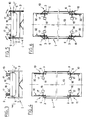
- the barge 2 which transports the deck or on which the deck must be loaded, is engaged between the legs 3 of the support structure 1, as shown in Figures 1 and 2.
- the deck of the platform has not been shown for reasons of simplification and insofar as it is not part of the invention and is not necessary for the understanding of the latter.
- the support structure 1 is a fixed structure, its legs 3 being fixed to the seabed 4 by piles 5 introduced by sinking into the bottom 4.
- the invention is also applicable in the case of a support structure floating maintained on the operating site of the marine platform by several anchor lines and / or by several tie rods anchored on the seabed 4, as is known in the technique of marine platforms.
- the barge 2 can be temporarily maintained longitudinally by known means such as tugs, a dynamic positioning system, hawsers, or even front anchor lines 7 and rear anchor lines 8, as shown in figure 2.
- known means such as tugs, a dynamic positioning system, hawsers, or even front anchor lines 7 and rear anchor lines 8, as shown in figure 2.
- the hawsers or the anchor lines are very tight, they cannot be enough to reduce the barge's movement of the barge to an acceptable value for the needs of the planned operation to install or remove the bridge. It is therefore usually necessary to provide additional means to prevent or reduce the barge movement of the barge to acceptable values.
- the known systems using "sticks" or plungers, with or without radial elastomer are fragile and / or difficult to implement in the presence of a strong swell.
- the present invention provides a method and a device making it possible to immobilize the barge 2 with regard to its movement of cavalry with respect to the support structure 1, while leaving the barge its other freedom of movement , in particular with regard to the heaving, rolling and pitching movements, the yawing and swerving movements being limited by other known means such as the flexible defenses 6 mentioned above.
- each buffer 9 10, 11 and 12 are installed on the deck of the barge 2 at the four corners thereof.
- the port front bumper 9 and the starboard aft bumper 12 are identical.
- the starboard front stop 10 and the port aft stop 11 are identical and symmetrical respectively to the stops 9 and 12 with respect to the longitudinal axis 13 of the barge 2.
- Each of the four buffers 9-12 can rotate in bearings, for example three bearings 14, 15 and 16 aligned in a direction parallel to the longitudinal axis of the barge 2, as shown in Figures 7 and 11 with regard to the buffer 9 , the other buffers being mounted in a similar manner to that shown in these two figures.
- each of the four buffers 9-12 is foldable from a substantially vertical retracted transport position ( Figures 3 and 4) to a horizontal working position ( Figures 5, 6, 7 and 11) in which the buffers protrude laterally outwards on the sides of the barge 2.
- the front buffers 9 and 10 face the front sides front extreme legs 3 of the support structure 1 which are oriented towards the front of the barge 2, while the rear buffers 11 and 12 face the rear sides of the rear extreme legs 3 of the support structure 1 which are oriented towards the back of the barge.
- Each of the four buffers 9-12 is connected by a cable 17 to a winch 18 ( Figures 3 to 6) which, when actuated, allows the corresponding buffer to be folded down from its transported-in position to its working-out position or vice versa.
- Each cable 17 passes around a pulley 19 mounted at the top of a mast 21 which is fixed to the bridge of the barge 2 (FIG. 11) between the winch 18 and the corresponding stop.
- each stopper can be constituted by a tubular structure comprising a tube 22, which is mounted so that it can both slide and rotate in the bearings 14, 15 and 16, a tube 23, one end of which is rigidly fixed to the tube 22 and which extends perpendicular thereto, a short tube 24 which is fixed to the other end of the tube 23 and which extends parallel to the tube 22, and a tube 25 whose ends are rigidly fixed to the tubes 22 and 24 and which extends obliquely with respect thereto.
- the four tubes 22-25 form an approximately triangular structure, the tube 25 constituting a strut allowing the tube 23 to withstand the horizontal forces to which it is subjected in service.
- the tube 23 carries a roller 26 which can both rotate around the axis of the tube 23 and slide along the tube 23.
- the roller 26 has in its surface peripheral a groove whose profile matches that of the external surface of the leg 3 of the support structure 1.
- the body of the roller 26 may for example be made of metal and its groove is preferably coated with a flexible lining 27 (FIG. 8) making it possible to establish good contact between the roller 26 and the leg 3 of the support structure 1.
- the lining 27 may for example be made of polyurethane.
- Each stopper is associated with a slide system 28 (FIGS. 7 and 9) which makes it possible to maintain the corresponding stopper, for example the stopper 9, in its horizontal working position when it is subjected to vertical forces in service.
- the slide system 28 can consist of a metal section 29 with an I-section, of the IPN beam type, which is fixed to the bridge of the barge 2 so as to extend parallel to the longitudinal axis thereof, and by an element 31 profiled in C and rigidly fixed, for example welded, to the tube 23.
- the element 31 is shown in engagement with the upper horizontal wing of the profiled 29.
- the tube 23 is supported by the profile 29 and can slide along the latter, but it is retained in its horizontal position and the stopper 9 cannot be raised.
- part of the upper horizontal flange of profile 29 is removed in the region of the right end of profile 29 so that the elements 29 and 31 of the slide system 28 can be brought into engagement with each other by a movement of rotation of the stopper 9 around the axis of the bearings 14-16 then by a movement of translation parallel to said axis, or that the elements 29 and 31 of the system with glisisère 28 can be released from each other, if desired, by a translational movement of the stopper 9 towards the right (seen in Figure 7) and then by an upward rotation around the axis of the bearings 14-16.
- Each of the four buffers 9-12 is associated with a control system 32 which allows the corresponding buffer to be moved parallel to the longitudinal axis of the barge 2 in order to bring said buffer into contact with the corresponding leg 3 of the support structure 1 , to keep it pressed elastically against said leg and then to block the stopper with respect to the barge 2 according to a process which will be described in detail below.
- the control systems 32 can be implemented in different ways. For example, they may be purely mechanical or electromechanical systems using linear actuators, springs and ratchet-controlled mechanisms. However, each control system 32 is preferably constituted by a hydraulic control system which will now be described.
- the four hydraulic control systems 32 are identical and therefore only one of these systems will be described, for example the one associated with the stopper 9.
- the hydraulic control system 32 essentially comprises a double-acting hydraulic cylinder 33 and a low-pressure accumulator 34 connected to the cylinder 33.
- the latter is arranged so to extend parallel to the longitudinal axis of the barge 2.
- the piston rod 35 of the jack 33 is coaxial with the tube 22 of the stopper 9 and it is connected to one end of the latter by a semi-link rigid 36 (best seen in Figure 22).
- the connection 36 has a certain degree of elasticity in the longitudinal direction so that it can be compressed elastically to a small extent, for example a few centimeters, for reasons which will appear later.
- the end of the body 37 of the jack 33 furthest from the tube 22 is connected to the bridge of the barge 2 by an articulated yoke 38.
- Two chambers 39 and 41 are formed in the body 37 of the cylinder 33 respectively on either side of its piston 42 ( Figures 7 and 22).
- the annular chamber 39 on the piston rod side 35 can be supplied with pressurized oil through a pipe 43 (FIG. 12).
- the chamber 41 of the jack 33 on the side of the yoke 38 can be placed in communication with the low pressure accumulator 34 through several closable orifices ( Figures 12, 23 and 24-26), the nature and operation of which will be described in detail further.
- these closable orifices are represented symbolically and globally by a single hole 44 and by a single needle 45.
- the low pressure accumulator 34 is preferably located directly above the body 37 of the jack 33 at its end on the yoke side 38, and it contains a certain volume of oil 46 and a gas or a gaseous mixture 47 under low pressure, on the order of a few bars. This gas tends to expel the oil 46 towards the chamber 41 of the jack 33, therefore pushing the piston 42 and its rod 35 out of the body 37 and, therefore, pushing the stopper 9 towards the corresponding leg 3 of the support structure 1.
- the quantity of oil 46 contained in the low pressure accumulator 34 is greater than the volume of oil necessary for the piston 42 to perform its maximum stroke in the body 37.
- the pressure of the gas 47 in the accumulator low pressure 34 must be sufficient to overcome the friction forces in the jack 33 and in the bearings 14-16.
- the closable orifices symbolically represented at 44 in FIG. 12, in reality comprise several piloted non-return valves 48, for example two valves 48, and at least one piloted valve 49 (for reasons of simplification of the drawing, we have simply shown a single piloted non-return valve 48 and a single piloted valve 49 in Figures 23 to 26).
- a pressure sensor 51 makes it possible to measure the pressure of the oil in the chamber 41 of the jack 33.
- valves 48 When the valves 48 receive a piloting signal controlling their opening, they establish a bi-directional communication at high flow rate between the interior cavity of the low pressure accumulator 34 and the chamber 41 of the jack 33 (FIG. 25). In the absence of a pilot signal, the valves 48 establish a high-speed unidirectional communication from the internal cavity of the accumulator 34 towards said chamber 41 when the pressure in the latter tends to become lower than that prevailing in the accumulator 34, and they close automatically when the pressure in chamber 41 tends to become greater than in accumulator 34. On the other hand, when it is opened by a piloting signal, the piloted valve 49 establishes a communication at low flow rate between the chamber 41 and a hydraulic fluid reservoir. Although this hydraulic fluid reservoir is represented in FIGS.
- the hydraulic fluid reservoir is preferably constituted by a reservoir separated from said accumulator and arranged for example on the deck of the barge 2 as is schematically indicated at 52 in FIG. 27.
- piloted non-return valves 48 and the piloted valve 49 allow the piston 42 and the piston rod 35 to work in three different modes at the discretion of an operator 53 (FIG. 12) acting on a control desk 54, or under the control of a programmable controller replacing said operator.
- hydraulic control is provided to control the opening of the piloted non-return valves 48 and of the piloted valve 49, although they could be electromagnetically controlled.
- a very low power, of the order of a few tens of kW, is sufficient to switch from one operating mode to another and to control the entire operation of stopping the movement of barge 2 cavalry.
- hydraulic power required for this purpose can come from a hydraulic power source 55, called hydraulic power plant.
- a single control desk 54 and a single hydraulic unit 55 may suffice for the four hydraulic control systems 32 respectively associated with the four buffers 9-12.
- the cylinder 33 of each hydraulic control system 32 has four working modes.
- the chamber 39 is supplied with oil under a pressure higher than the pressure prevailing in the chamber 41 and in the low pressure accumulator 34. This has the effect of bringing in the piston rod 35 of the jack 33 in the body 37 and bring it into its fully retracted position if it was not already there.
- the valves 48 are controlled so as to be kept open.
- the oil pressure in the chamber 39 is released. This can be obtained for example by putting the pipe 43 in communication with the hydraulic fluid reservoir.
- the piston rod 35 is free to go out or to go into the body 37 of the jack 33 according to the direction of movement of the barge 2 under the effect of the low pressure in the accumulator 34, on the one hand, or under the effect of the thrust exerted by the leg 3 of the support structure 1, on the other hand, when the contact between the latter and the roller 26 has been established.
- This operating mode is obtained by controlling the non-return valves 48 so as to keep them open (high-speed bidirectional communication between the accumulator 34 and the chamber 41) and by maintaining closed the pilot-operated valve 49.
- This operating mode corresponds to FIGS. 16, 17, 18 and 25.
- the piston rod 35 is free to leave the body 37 of the cylinder 33, but it can no longer enter it.
- This operating mode is obtained by operating the valves 48 like ordinary non-return valves allowing the entry of oil into the chamber 41 from the accumulator 34, but blocking the exit of the oil from the chamber 41. towards the accumulator 34 (high-speed unidirectional communication from the accumulator 34 towards the chamber 41), and keeping the pilot-operated valve 49 closed.
- This operating mode corresponds to FIGS. 19 to 21 and 24.
- the piston rod 35 is subjected to a force tending to make it enter the body 37 of the cylinder 33.
- Slow and controlled re-entry of the piston rod 35 is made possible by controlling the valve 49 so as to keep it open.
- a throttle 56 (FIG. 27) is associated with the valve 49 and plays the role of a flow limiter to slow down the re-entry of the rod 35 into the body 37.
- the valve 49 is again piloted so as to put it in the closed position, the retraction of the rod 35 immediately ceases, because it is blocked by the oil contained in the chamber 41, which can no longer come out of it by the valves 48 or through valve 49.
- Phase 1 start of the operation - observation period ( Figures 3 and 4)
- the barge 2 is in position between the legs 3 of the support structure 1. It is held by temporary means such as anchor lines 7 and 8 and / or tugs (not shown) or also a dynamically positioned system, also (not shown), all of these means being well known and not part of the present invention. With the aid of these temporary holding means, it is made so that the average longitudinal position of the barge 2, between the two extreme longitudinal positions which it takes due to the alternating movement of cavalry, is close to the position of ideal immobilization.
- the buffers 9-12 are in their substantially vertical retracted transport position and the jacks 33 operate in mode 1, so that their piston rod 35 is fully retracted.
- the total amplitude of the movement of barge 2 is measured, that is to say the total front-rear stroke of the barge due to its alternating movement of barge.
- This total amplitude or stroke must be and remain less than the maximum admissible stroke for the buffers 9-12 (this maximum admissible stroke is determined, in the embodiment described above, by the distance between two successive bearings 14 and 15 or 15 and 16 and / or by the length of the jack 33; it is therefore determined by construction and can be chosen as large as desired).
- This is a necessary condition in order to be able to lower the buffers 9-12 into their horizontal working position.
- a known prior calculation will have determined the maximum swell conditions allowing this operation to be carried out.
- the barge 2 will have been introduced between the legs 3 of the support structure 1 only if these conditions are met.
- the relative position of the barge 2 and the support structure 1 can be measured by a system of visual cues or by any other known measurement system not forming part of the invention.
- Phase 2 folding down the bumpers ( Figures 5, 6, 11, 13, 14 and 15.
- the bumpers 9-12 are then folded down or tilted in order to put them in their horizontal working position, that is to say in a plane parallel to the plane of the bridge of the barge 2.
- the winch 18 and the cable 17 which pass around the pulley 19 at the top of the mast 21.
- the winch 18 only serves as a brake since the stopper can tilt under the effect of its own weight.
- the winch 18 would be used as a driving member if the stopper had to be raised.
- each stopper is tilted in its horizontal position while it is in its extreme outer position relative to the support structure 1, that is to say that the front stops 9 and 10 are tilted when the barge 2 arrives or is at the end of its forward stroke, while the rear buffers 11 and 12 are folded down when the barge 2 arrives or is at the end of its rearward stroke.
- each stop 9-12 rests on the end of the profile 29 of the slide 28 which is devoid of an upper horizontal wing (FIGS. 10, 13 and 15).
- each stopper being able to be raised in its vertical position using the cable 17 and the winch 18 associated therewith.
- the operation manager triggers the output of the piston rods 35 from the cylinders 33 by releasing the pressure in the chamber 39 of the cylinder body and by operating the latter in mode 2 .
- the chamber 39 of the cylinders 33 is still maintained under a low oil pressure, lower than that of the accumulator 34, to avoid a vacuum in the chamber 39 which could hinder the re-entry of the rod 35 in the body of the jack 33 when, for example in the case of the stopper 9, the barge moves in the direction of the arrow G in FIG. 18.
- the other five movements of the barge 2 create at the level of the rollers 26, that is to say a movement of rotation of the rollers which start rolling on the legs 3 of the support structure 1 as regards the heaving movements, roll and pitch, a sliding movement of the roller on the corresponding tube 23 with regard to swerving and yawing movements.
- the upper and lower limits of excursion of the rollers 26 will have been observed beforehand to ensure that there is no obstacle along the legs 3 of the support structure 1 and that these are sufficiently high.
- the authorized sliding stroke of the rollers 26 on the corresponding tube 23 must be compatible with the previously observed amplitude of the swerve movement of the barge 1.
- the operation is always reversible, the chambers 39 of the jacks 33 being able to be pressurized to retract the piston rods 35 and the buffers to which they are respectively attached.
- the pump allowing this repressurization of the chambers 39 to be carried out is preferably chosen so as to be able to ensure a sufficient flow rate so that the stopper has a withdrawal speed greater than the cavalry speed of the barge 2.
- Phase 4 immobilization of the barge on the fly ( Figures 19, 20 and 21)
- the rollers 26 of the buffers 9-12 were brought into contact with the corresponding legs 3 of the support structure 1 and they are kept pressed elastically against said legs 3 by the low pressure prevailing in the accumulators 34 and the chambers 41 of the jacks 33, but the barge 2 continues to wander and it is therefore now necessary to immobilize it.
- the barge 2 will first of all be brought into abutment either on the front buffers 9 and 10, or on the rear buffers 11 and 12. This choice is arbitrary but must be defined in advance.
- the barge 2 is brought into abutment on the front buffers 9 and 10 by passing the jacks 33 associated with these bumpers from mode 2 to mode 3, by deactivating the control of the valves 48.
- the transition from mode 2 to mode 3 is not carried out at any time. If it is carried out while the oil enters the chamber 41 of the body of the jack 33, that is to say when the barge 2 moves from back to front, the valves 48 will close smoothly when the direction of oil flow will change, that is, when the barge begins to move back and forth. If, on the contrary, the transition from mode 2 to mode 3 is carried out while the oil leaves the chamber 41 in the direction of the accumulator 34, the valves 48 will close immediately and violently.
- the operator or the automaton will also take into account the reaction time of the valves, which is of the order of a few tenths of a second.
- the transition from mode 2 to mode 3 will therefore logically be carried out when the barge 2, at the end of the rear stroke, begins a new forward stroke.
- the oil begins to come out of the accumulators 34 and to enter the chambers 41 of the jacks 33 associated with the front buffers 9 and 10.
- the valves 48 will therefore remain open throughout the source from behind in front of the barge 2 , that is, for a few seconds. This time constitutes comfortable security so that the deactivation of the control of the valves 48 of the jacks 33 associated with the front buffers 9 and 10 is carried out normally.
- valves 48 of the jacks associated with the front buffers close gently.
- the oil contained in the chamber 41 of the jack 33 associated with each front stopper 9 or 10 can then no longer exit from this chamber 41 towards the accumulator 34, and it is then subjected to a compressive force which increases in proportion to the swell force on barge 2, tending to make it move back.
- the front buffers 9 and 10 are blocked relative to the barge 2 by the oil trapped in the chamber 41 of the two front cylinders 33. The barge 2 is thus blocked in the direction of front to back.
- the immobilization of the barge 2 occurred when its runoff speed was zero (at the time of the reversal of the direction of the runoff movement). Consequently, the immobilization took place without shock or dynamic force which would have been induced by the mass of the barge 2 and its load, if it had been in motion. This avoids having to dampen the kinetic energy of the barge and its moving load.
- the only force gradually applied, starting from a zero value, to the front buffers 9 and 10 and to the support structure 1 is the longitudinal component of the forces applied by the swell to barge 2. This component can, at its maximum, reach a few hundred tonnes.
- the buffers 9-12 and the jacks associated therewith 33 must be dimensioned accordingly.
- the jacks 33 associated with the rear buffers 11 and 12 operated in mode 2.
- the rear cylinders 33 that is to say the cylinders associated with the rear buffers 11 and 12, so that they too can play their role of stop in the opposite direction. This must be done in the same alternation of the reciprocating movement of the swell as that during which the barge 2 was abutted on the front buffers 9 and 10. If this were not the case, the barge 2 would be pushed forward by the swell beyond the front blocking point and may be beyond the area in which the buffers can operate normally.
- valves 48 associated with the rear jacks 33 are deactivated as soon as a significant pressure appears in the chamber 41 of the front jacks 33. This means that the valves 48 associated with the front jacks 33 have just closed to block the barge 2 on the front buffers 9 and 10. This can be detected by means of the pressure sensors 51 associated with the front cylinders 33.
- the pitching of the barge is not limited by any particular device and the buffers 9-12 must adapt to it. It is assumed that the immobilization of barge 2 occurred when it was horizontal. If we now consider the barge 2 with its maximum pitch due to pitching, we see that the distance between the support points of the front buffers and rear buffers on the corresponding legs 3 of the support structure 1 has increased compared to the value of this distance in horizontal position of the barge 2. The increase in the value of this distance can be of the order of a few centimeters. If the buffers 9-12 were perfectly rigid, this distance could not increase and the buffers 9-12 and the legs 3 of the support structure 1 would then be subjected to forces that can reach significant values.
- the buffers 9-12 must have a certain flexibility in compression. This flexibility is obtained on the one hand thanks to the flexible lining 27 of the rollers 26 and on the other hand thanks to the semi-rigid connection 36 between the piston rod 35 of the jacks 33 and the tube 22 of the tubular structure forming the buffers. 9-12.
- Phase 5 fine adjustment of the relative position of the barge in relation to the support structure
- the barge 2 was immobilized with respect to the support structure 1.
- the immobilization position of the barge 2 does not necessarily correspond to the ideal position in which one would like the barge to be immobilized, for example to be able to install or remove the deck from a marine platform.
- the position of the barge 2 at the time of its immobilization can only be estimated in advance and the immobilization position obtained can be spaced a few decimeters from the ideal position or desired position. We will assume for example that it is necessary to move the barge 2 back to bring it into its desired position.
- the value of the pressure in the chamber 41 of the front cylinders 33 reaches a significant value (which can be detected using the pressure sensor 51) and, when the pressure reaches this value, we operates the front cylinders 33 in mode 4, that is to say by controlling the valve 49 of the front cylinders 33 so as to open this valve.
- the oil contained in the chamber 41 of the front cylinders 33 can slowly escape towards the reservoir 52 (FIG. 27), thus allowing the barge 2 to reverse slowly, until the valve 49 of the cylinders before is piloted again in the direction of its closing.
- valves 48 of the rear cylinders 33 open automatically and allow the oil to enter the chamber 41 of the rear cylinders, so that their piston rod 35 comes out and the rear buffers 11 and 12 are kept in contact. with the corresponding legs 3 of the support structure 1. If at the time of closing the valve 49 of the front cylinders 33 the barge 2 has still not arrived in the desired position, the operation described above can be repeated during of the next alternation of the movement of cavalry taking place in the same direction, and this as many times as is necessary to bring the barge 2 into the desired position.
- the body of the jack 33 comprises a tubular part 37, closed in leaktight manner on the side of the yoke 38 by a bottom or end plug 61 screwed or welded to the tube 37.
- a bottom or end plug 61 screwed or welded to the tube 37.
- an ear 62 which is itself connected to the yoke 38 by an axis 63. It is by this ear 62, by this axis 63 and by this yoke 38 that the forces immobilizing the barge 2 pass. with respect to the support structure 1.
- These elements must therefore be dimensioned accordingly.
- annular bottom or plug 64 allowing the piston rod 35 to pass through its middle is screwed onto the tube 37.
- the seal is ensured by seals not shown between the piston 42 and the tube 37, between the piston rod 35 and the annular plug 64, and between the latter and the tube 37.
- the semi-rigid connection 36 which connects the piston rod 35 of the jack 33 to the tube 22 of the tubular structure forming the associated stopper, comprises a piece 65 of elastomeric material, which is supported on a sheet 66 welded inside the tube 22 and stiffened by several gussets 67 themselves welded to the sheet 66, to the tube 22 and to each other.
- a nozzle or pressure plate 68 distributing the pressure in the part 65 of elastomeric material, is screwed onto the end of the piston rod 35.
- a flange 69 bolted to the end of the tube 22 and cooperating with the pressure plate 68 allows the piston rod 35 of the jack 33 to pull the associated stopper in the direction of the yoke 38 when the chamber 39 of the jack is supplied with oil under pressure.
- the piece 65 of elastomeric material is mounted between the support plate 66 and the pressure plate 68 so as to be not or very little compressed when the stopper is at rest.
- the thickness and / or the elastomeric material of the part 65 is chosen in such a way that this part only compresses very slightly (a few centimeters or ten centimeters) compared to the run-out when the stopper is in contact with a leg 3 of the support structure and pressed against it by the force of the swell acting on the barge.
- the piece 65 of elastomeric material is designed to be able to withstand the pinching effect due to pitching, without however creating excessively excessive forces in the device.
- the accumulator 34 consists of a tube 71 provided with flanges at each of its ends, a bottom plate 72 and a cover 73. These three elements are bolted to each other.
- the bottom plate 72 of the accumulator 34 is also bolted to an annular connection flange 74 which is welded to the tube 37 forming the body of the jack 33, near the end plug 61 thereof.
- the bolted connections mentioned above are sealed thanks to seals not shown.
- the piloted non-return valves 48 and the piloted valve or valves 49 which are intended to put the accumulator 34 in communication with the chamber 41 of the jack 33, are mounted in the bottom plate 72 of the accumulator.
- the valve 48 and the valve 49, shown in Figures 23 to 26 each in a single copy, may in fact, for reasons of reliability or passage section, be more numerous.
- the set of pipes 75 connecting the hydraulic unit 55 to the hydraulic control system 32 groups the oil supply pipe 43 of the chamber 39 of the jack 33, the pipe 76 for controlling the valve 48, the pipe 77 for measuring the oil pressure in the chamber 41, the two pipes 78 for controlling the valve 49, the pipe 79 for discharging d pressurized oil from the chamber 41 through the valve 49 when open, and the oil return pipe 81 in the accumulator 34.
- the pipe 82 is used for inflating the low pressure accumulator 34 with a gas or a gas mixture such as air or nitrogen.
- the pipe 77 contains the conductors transmitting the output signal from the pressure sensor to the control console 54.
- the pressure sensor 51 could be placed at a distance from the bottom plate 72, for example on the cover 73 or in the hydraulic unit 55. In the latter case, the pipe 77 places the chamber 41 of the jack 33 in communication with the pressure sensor.
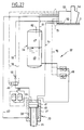
- FIG. 27 represents a hydraulic diagram of the hydraulic control system 32 according to the invention.
- the piloted valve 49 is represented in the form of a distributor with two orifices and two positions, which can be piloted on both sides by a piloting pressure applied by one or the other of the two pipes 78. It is however very obvious that the distributor 49 can be controlled by pressure on one side and returned by spring on the other side. For example, the distributor 49 can be held in its closed position by a spring, and it can be switched into its open position by pressure control.
- FIG. 27 two high pressure accumulators 83 have also been shown, which are in communication by a pipe 84 with the chamber 41 of the cylinder 33.
- the accumulators 83 can be used to reduce the effect of an accidental impact on the associated stopper to the cylinder 33.
- the high pressure accumulators 83 can for example be installed on the bottom plate 72 of the low pressure accumulator 34.
- FIG. 27 shows two high pressure accumulators 83, it goes without saying that the invention does not is not limited to this number.
- the buffers 9 and 10 could be arranged so as to act on the surfaces vertical front of the rear legs 3 and the buffers 11 and 12 could be arranged so as to act on the surfaces vertical rear of the front legs 3, if the support structure 1 does not include, between the front and rear legs 3 of the frames which may hinder the longitudinal movements of the buffers 9-12.
- the device according to the invention is usable to immobilize, to within its internal elasticity, any floating marine structure and animated by a movement of cavitation due to the swell, compared to another fixed marine structure or itself floating.
- the device according to the invention can be used to immobilize, from the point of view of the runaway, two ships placed side by side or a ship docked at a pier. In these two cases, the device according to the invention may comprise only two stops.
- the bumpers can be installed either on the vessel or on the jetty, the vertical bearing surfaces for the bumpers then being provided, as the case may be , either on the pier or on the ship.
Landscapes
- Engineering & Computer Science (AREA)
- Mechanical Engineering (AREA)
- Ocean & Marine Engineering (AREA)
- General Engineering & Computer Science (AREA)
- Combustion & Propulsion (AREA)
- Chemical & Material Sciences (AREA)
- Structural Engineering (AREA)
- Civil Engineering (AREA)
- Environmental & Geological Engineering (AREA)
- General Life Sciences & Earth Sciences (AREA)
- Mining & Mineral Resources (AREA)
- Paleontology (AREA)
- Life Sciences & Earth Sciences (AREA)
- Earth Drilling (AREA)
- Vibration Prevention Devices (AREA)
- Bridges Or Land Bridges (AREA)
- Revetment (AREA)
Applications Claiming Priority (2)
| Application Number | Priority Date | Filing Date | Title |
|---|---|---|---|
| FR9404312 | 1994-04-12 | ||
| FR9404312A FR2718474B1 (fr) | 1994-04-12 | 1994-04-12 | Procédé et dispositif anticavalement pour structures marines. |
Publications (1)
| Publication Number | Publication Date |
|---|---|
| EP0677437A1 true EP0677437A1 (de) | 1995-10-18 |
Family
ID=9462002
Family Applications (1)
| Application Number | Title | Priority Date | Filing Date |
|---|---|---|---|
| EP95400778A Withdrawn EP0677437A1 (de) | 1994-04-12 | 1995-04-07 | Verfahren und Vorrichtung gegen die Längsbewegung von Wasserfahrzeugen |
Country Status (8)
| Country | Link |
|---|---|
| US (1) | US5527132A (de) |
| EP (1) | EP0677437A1 (de) |
| JP (1) | JP2840567B2 (de) |
| KR (1) | KR950032910A (de) |
| CN (1) | CN1115296A (de) |
| BR (1) | BR9501527A (de) |
| FR (1) | FR2718474B1 (de) |
| NO (1) | NO951426L (de) |
Families Citing this family (7)
| Publication number | Priority date | Publication date | Assignee | Title |
|---|---|---|---|---|
| RU2422318C2 (ru) * | 2005-12-22 | 2011-06-27 | Блювотер Энерджи Сервисиз Б.В. | Система для швартовки судна в море |
| US20090110484A1 (en) * | 2007-10-24 | 2009-04-30 | Fillingame O Wayne | Storm surge breaker system, barrier system and method of constructing same |
| US20110305522A1 (en) | 2010-06-15 | 2011-12-15 | James Allan Haney | Floatover arrangement and method |
| CN102464096B (zh) * | 2010-11-07 | 2014-05-07 | 中国石化集团胜利石油管理局井下作业公司 | 一种用于海上井口平台防撞击保护的重大安全装置 |
| CN105000149A (zh) * | 2015-08-12 | 2015-10-28 | 杨玉相 | 具有防撞功能的轮船单三角形框架防护设备 |
| KR102175552B1 (ko) * | 2018-10-30 | 2020-11-06 | 현대중공업 주식회사 | 중력 기반 해양구조물 |
| CN118289168B (zh) * | 2024-04-16 | 2024-11-19 | 卓控海洋装备技术(广州)有限公司 | 一种船舶侧面抗冲击减震装置 |
Citations (3)
| Publication number | Priority date | Publication date | Assignee | Title |
|---|---|---|---|---|
| US4003329A (en) * | 1973-07-26 | 1977-01-18 | Fmc Corporation | Combination positioning and propelling apparatus for barges |
| US4008678A (en) * | 1975-10-20 | 1977-02-22 | Sun Shipbuilding And Dry Dock Co. | Ship mooring system |
| US5201274A (en) * | 1991-10-22 | 1993-04-13 | Isaac Rinkewich | Ship mooring system |
Family Cites Families (3)
| Publication number | Priority date | Publication date | Assignee | Title |
|---|---|---|---|---|
| US1094610A (en) * | 1913-06-21 | 1914-04-28 | Frederick Steinhauer | Boat-fastening means. |
| US4066030A (en) * | 1976-03-01 | 1978-01-03 | Louis Milone | Mechanical coupling for marine vehicles |
| JPH0635904Y2 (ja) * | 1990-04-03 | 1994-09-21 | 五洋建設株式会社 | 繋留装置 |
-
1994
- 1994-04-12 FR FR9404312A patent/FR2718474B1/fr not_active Expired - Fee Related
-
1995
- 1995-04-05 US US08/417,375 patent/US5527132A/en not_active Expired - Fee Related
- 1995-04-07 EP EP95400778A patent/EP0677437A1/de not_active Withdrawn
- 1995-04-10 KR KR1019950008268A patent/KR950032910A/ko not_active Withdrawn
- 1995-04-11 CN CN95104307A patent/CN1115296A/zh active Pending
- 1995-04-11 BR BR9501527A patent/BR9501527A/pt not_active Application Discontinuation
- 1995-04-11 NO NO951426A patent/NO951426L/no unknown
- 1995-04-12 JP JP7087103A patent/JP2840567B2/ja not_active Expired - Lifetime
Patent Citations (3)
| Publication number | Priority date | Publication date | Assignee | Title |
|---|---|---|---|---|
| US4003329A (en) * | 1973-07-26 | 1977-01-18 | Fmc Corporation | Combination positioning and propelling apparatus for barges |
| US4008678A (en) * | 1975-10-20 | 1977-02-22 | Sun Shipbuilding And Dry Dock Co. | Ship mooring system |
| US5201274A (en) * | 1991-10-22 | 1993-04-13 | Isaac Rinkewich | Ship mooring system |
Also Published As
| Publication number | Publication date |
|---|---|
| KR950032910A (ko) | 1995-12-22 |
| NO951426L (no) | 1995-10-13 |
| JP2840567B2 (ja) | 1998-12-24 |
| CN1115296A (zh) | 1996-01-24 |
| BR9501527A (pt) | 1995-11-14 |
| JPH0840363A (ja) | 1996-02-13 |
| FR2718474A1 (fr) | 1995-10-13 |
| US5527132A (en) | 1996-06-18 |
| FR2718474B1 (fr) | 1996-05-24 |
| NO951426D0 (no) | 1995-04-11 |
Similar Documents
| Publication | Publication Date | Title |
|---|---|---|
| EP0654564B1 (de) | Verfahren zur unterwasser Installation einer Ölplattform auf einer Tragekonstruktion | |
| EP2049388B1 (de) | Für hohle tiefen geeigneter saugpfahl | |
| CA2731070C (fr) | Support flottant comprenant un touret equipe de deux bouees d'amarrage de lignes d'ancrage et de conduites de liaison fond/surface | |
| EP0018891B1 (de) | Untersee-Fahrzeug zum Baggern und Hochheben von Mineralien aus grossen Tiefen | |
| CA2714637A1 (fr) | Support flottant comprenant un touret equipe d'une bouee d'amarrage de conduites de liaison fond/surface deconnectable | |
| WO2004001180A1 (fr) | Conduite de guidage telescopique de forage en mer | |
| EP3902742A1 (de) | Andockvorrichtung für ein unterwasserfahrzeug | |
| FR2941434A1 (fr) | Systeme de transfert d'un produit fluide et sa mise en oeuvre | |
| EP2125503B1 (de) | Vorrichtung zum schneiden und öffnen/schliessen eines loches in eine wand auf dem meeresgrund | |
| EP2454149A1 (de) | Katamaran für montage, transport und installation einer meereswindkraftanlage auf dem meeresboden | |
| WO2009118467A2 (fr) | Méthode d'installation de colonne sous-marine montante | |
| FR3091258A1 (fr) | Dispositif d’accueil pour un véhicule sous-marin | |
| FR2595750A1 (fr) | Compensateur de deplacement pour un moufle fixe, notamment pour une tour de forage petrolier | |
| WO1996000359A1 (fr) | Dispositif de pose de conduites flexibles a partir d'un support flottant | |
| FR2957649A1 (fr) | Procede de depose d'une ligne sous-marine au fond de la mer | |
| EP0677437A1 (de) | Verfahren und Vorrichtung gegen die Längsbewegung von Wasserfahrzeugen | |
| EP1568600B1 (de) | Vorrichtung und Verfahren zum Befestigen einer Basiskonstruktion auf einer Wandfläche am Meeresgrund | |
| EP2788643B1 (de) | Anordnung zum fluidtransport durch eine rohrleitung und zugehörige schwimmende struktur | |
| WO2004087495A2 (fr) | Dispositif et procede de stabilisation et de controle de la descente ou remontee d’une structure lourde entre la surface et le fond de la mer | |
| EP1449763A1 (de) | Verfahren und Installation zur Ausflussrückgewinnung am Meer durch Benutzung eines Pendelreservoirs | |
| EP0054477B1 (de) | Antriebseinrichtung mit Zylindern zur Erzeugung der kontinuierlichen Bewegung eines länglichen Gegenstandes in Richtung seiner Achse und/oder zum Bewegen eines Elementes längs diesem Gegenstand | |
| EP0451058B1 (de) | Verfahren und Vorrichtung zum Ablegen eines Steigrohres in einem Zugangsbohrloch einer Salzkaverne für Gasspeicherung | |
| WO2024246446A1 (fr) | Dispositif de mise à l'eau ou d'émersion d'une structure flottante | |
| FR2683203A1 (fr) | Radeau de sauvetage gonflable. | |
| WO2016046132A1 (fr) | Systeme oceanographique et procede de commande |
Legal Events
| Date | Code | Title | Description |
|---|---|---|---|
| PUAI | Public reference made under article 153(3) epc to a published international application that has entered the european phase |
Free format text: ORIGINAL CODE: 0009012 |
|
| AK | Designated contracting states |
Kind code of ref document: A1 Designated state(s): BE DE DK ES GB GR IE IT LU NL PT |
|
| 17P | Request for examination filed |
Effective date: 19960329 |
|
| GRAG | Despatch of communication of intention to grant |
Free format text: ORIGINAL CODE: EPIDOS AGRA |
|
| GRAG | Despatch of communication of intention to grant |
Free format text: ORIGINAL CODE: EPIDOS AGRA |
|
| GRAG | Despatch of communication of intention to grant |
Free format text: ORIGINAL CODE: EPIDOS AGRA |
|
| GRAH | Despatch of communication of intention to grant a patent |
Free format text: ORIGINAL CODE: EPIDOS IGRA |
|
| 17Q | First examination report despatched |
Effective date: 19980126 |
|
| STAA | Information on the status of an ep patent application or granted ep patent |
Free format text: STATUS: THE APPLICATION IS DEEMED TO BE WITHDRAWN |
|
| 18D | Application deemed to be withdrawn |
Effective date: 19980616 |