EP0679492A2 - Kombinierte Formträger und Gestängevorrichtung - Google Patents
Kombinierte Formträger und Gestängevorrichtung Download PDFInfo
- Publication number
- EP0679492A2 EP0679492A2 EP95810231A EP95810231A EP0679492A2 EP 0679492 A2 EP0679492 A2 EP 0679492A2 EP 95810231 A EP95810231 A EP 95810231A EP 95810231 A EP95810231 A EP 95810231A EP 0679492 A2 EP0679492 A2 EP 0679492A2
- Authority
- EP
- European Patent Office
- Prior art keywords
- plates
- mold
- improvement
- motion
- support
- Prior art date
- Legal status (The legal status is an assumption and is not a legal conclusion. Google has not performed a legal analysis and makes no representation as to the accuracy of the status listed.)
- Granted
Links
Images


Classifications
-
- B—PERFORMING OPERATIONS; TRANSPORTING
- B29—WORKING OF PLASTICS; WORKING OF SUBSTANCES IN A PLASTIC STATE IN GENERAL
- B29C—SHAPING OR JOINING OF PLASTICS; SHAPING OF MATERIAL IN A PLASTIC STATE, NOT OTHERWISE PROVIDED FOR; AFTER-TREATMENT OF THE SHAPED PRODUCTS, e.g. REPAIRING
- B29C45/00—Injection moulding, i.e. forcing the required volume of moulding material through a nozzle into a closed mould; Apparatus therefor
- B29C45/17—Component parts, details or accessories; Auxiliary operations
- B29C45/26—Moulds
- B29C45/32—Moulds having several axially spaced mould cavities, i.e. for making several separated articles
- B29C2045/326—Supporting means for the central mould plate
Definitions
- the present invention relates to injection molding machines and relates, in particular, to machines having a plurality of axially arranged mold stations each station having cooperating mold plates defining mold cavities in well known fashion.
- This mold arrangement is known in the art as a stack mold.
- overstroke is intended to mean intentional opening of the various mold stations a distance beyond the normal open stroke distance of the normal cycle of operation.
- a set of mold plates in the disclosed embodiment of the present invention includes mold plates, per se, and support plates to which the mold plates are attached, sometimes referred to collectively as a "set of plates”.
- a principal feature of the present invention is the provision of a novel means for supporting a stack mold having a plurality of molding stations.
- a further important feature of the invention is the provision of a simple, durable mechanism for opening and closing all molds at a plurality of molding stations simultaneously, precisely and with uniform stroke.
- a further feature is the provision of mold support means and mold actuating means which facilitates rapid, and convenient installation and removal of elements of multilevel molds (a plurality of axially arranged molding stations, i.e. stack mold) with minimum dismantling of molding machine.
- a still further feature of the invention is the provision of a novel method of opening and closing a plurality of axially arranged mold stations simultaneously and precisely.
- the present embodiment of the invention includes a basic machine frame including the classic tie bars which extend, in upper and lower pairs, from a fixed platen at one end to the machine frame at the opposite end of the tie bars.
- a movable platen reciprocates along the upper and lower pairs of tie bars.
- a central set of mold plates are received in a support member which, in turn, is supported by and is movable along the upper and lower tiers of tie bars.
- the central set of mold plates are readily removable in that they may be lifted vertically free of the support member.
- Correspondingly new or replacement central plates are installed by merely lowering the plates until they bottom on the support member.
- a primary crank mechanism is pivotally connected to the central set of mold plates via the support member and is linked pivotally at opposed ends to the movable platen and to the fixed platen.
- the connection to the platens is accomplished by pivotally mounted links.
- the primary crank mechanism straddles the injection molding machine and exists in the form of a pair of primary cranks which are spaced outwardly of the tie bars. To and fro motion of the movable platen actuates the primary crank mechanism maintaining the central mold plates equidistant from the fixed and movable platens as the molding machine cycles from open to closed positions.
- a secondary crank mechanism comprising in the disclosed embodiment, opposed pairs of smaller cranks supported pivotally and individually by sets of mold plates which are positioned on opposite sides of the central set.
- One end of the secondary cranks are linked pivotally to opposite sides of the central plates and the opposite end of a first pair of secondary cranks are linked pivotally to the movable platen while the opposite end of a second pair of secondary cranks are linked pivotally to the fixed platen.
- the secondary cranks are disposed inwardly of the machine tie bars in opposed pairs.
- motion of the movable platen drives the primary cranks and in so doing drives the secondary cranks so that the primary and secondary cranks provide the motion to open and close the mold stations in a precise and simultaneous manner which will be more apparent as this specification proceeds.
- crank arrangement be duplicated axially to operate many axially arranged mold stations.
- Sets of mold plates (second and third sets) on opposite sides of the central set of mold plates (first set) are supported by pairs of laterally spaced pins projecting from the mold plates which are fastened to the movable and fixed platens, respectively.
- the pairs of pins are offset vertically so as to avoid interference as the mold stations open and close.
- the pins are received in sleeve bearings or bushings formed in the upper ends of the second and third sets of mold plates.
- auxiliary support means are provided in the form of "outriggers" extending from the second and third sets of mold plates.
- the outriggers are bearing means or shoes which bear upon and move along the upper pair of tie rods thus augmenting pin support in the overstroked condition.
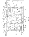
- the reference numeral 11 indicates, generally, a portion of an injection molding machine comprising a plurality of mold stations A, B, C and D, all in the open mold position, disposed between a fixed platen 12 and a movable platen 13 with a pair of upper tie bars 14 and 16 and a pair of lower tie bars 17 and 18.
- Mold stations A and B are supplied with moldable material via supply conduit S and mold stations C and D are supplied via conduit S'.
- the tie bars are secured at one end to fixed platen 12 and at the opposite end to a machine frame member, not shown.
- the movable platen 13 is supported by and is moved, to and fro, along the tie bars to open and close the mold stations by conventional drive means such as a hydraulic ram, not shown.
- a central set of mold support plates 19 and 21 carrying mold plates 25 and 30 are received in and supported by support member 22 in turn, carried movably by the lower pair of tie bars 17 and 18 and stabilized by engagement with an upper pair of the bars 14 and 16.
- the plates 19 and 21 and all associated mold plates comprising mold stations A-D are removable as an assembly by lifting the assembly vertically free of the support member 22.
- the support member 22 includes a pair of shoes or bearings 50 which engage and ride along upper tie bars 14 and 16 and a pair of shoes 55 which engage and ride along the lower tie bars 17 and 18 thereby guiding and stabilizing support member 22.
- the upper end of the plates 19 and 21 are formed with primary and secondary sleeve bearings or bushings 23 and 24 operable to receive ends of guide or support pins 26 and 27 respectively. That is, a pair of pins 26-26 are received in a pair of primary bushings 23-23 and a pair of pins 27-27 are received in the secondary bushings 24-24.
- Reference numerals are hyphenated in the drawings to indicate pairs. Opposite ends of the pairs of pins 26-26 and 27-27 are fastened to the movable platen 13 and the fixed platen 12 by means of plates 15 and 20, respectively.
- the reference numerals 28 and 29 denote pairs of clearance holes for the guide pins when the mold stations reach the closed position as is most apparent in Figure 2.
- a second set of plates 31 and 32, supporting mold plates 33 and 34, and a third set of plates 36 and 37 supporting mold plates 38 and 39 are also formed with pairs of primary and pairs of secondary bushings 41-41 and 42-42 respectively.
- the primary bushings 41-41 of the second set of plates 31 and 32 receive pins 26-26 to support the second set of plates while the pair of secondary bushings 42-42 provide additional support for the pair of pins 27-27 when the molds are in the closed position.
- the third set of plates 36 and 37 are supported by the engagement of the pair of pins 27-27 in the secondary bushings 42-42 while the primary bushing 41-41 of this set of plates provide additional support for the pins 26-26 as the mold stations close.
- the reference numeral 43 denotes the mold plate which cooperates with mold plate 33 while the reference numeral 44 denotes the mold plate which cooperates with mold plate 39.
- a pair of primary cranks 46 (only one shown in Figure 1) are mounted pivotally to the plate support member 22 on opposed sides of the member 22. Ends of the crank 46 are connected pivotally by means of pivot links 47 and 48 to movable platen 13 and fixed platen 12, respectively.
- Each of the second and third sets of plates (31 and 32 and 36 and 37) support pivotally pairs of secondary cranks 49 and 51 (only one crank of each pair shown in Figure 1).
- One end of the secondary cranks are connected by pivot links 52 and 53 to central plates 19 and 21 and at their opposite ends are connected to plates 15 and 20 respectively.
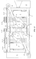
- Figure 3 shows the mold stations in the overstroked condition providing wide spacing between mold plates to facilitate servicing. Note that in the Figure 3 position of the mold stations the pins 26-26 and 27-27 have withdrawn from central plates 19 and 21 leaving the ends of the pins without the support normally provided by central plates. In order to compensate for this loss of support in the overstroked condition the second and third sets of mold plates are provided with outriggers or auxiliary bearings 54 and 56 as best seen in Figure 5. These bearings bear upon and move along the upper tier of tie bars 14 and 16.
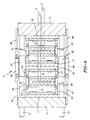
- FIG. 7 an alternative mechanism for opening and closing the mold plates is shown schematically wherein fixed platen 120 and movable platen 130 straddle mold stations A, B, C and D, illustrated in the closed condition.
- a rack 61 (first rack) is fastened at one end to fixed platen 120 and the opposite end is supported and engaged by pinion 62 (first pinion) carried by movable platen 130.
- a primary rack 63 (second rack) is fastened at one end to a set of central mold plates (first set) via plate support member 220 and the opposite end is supported and engaged by pinion 64 (second pinion).
- Pinions 62 and 64 are keyed together so that they rotate in unison upon shaft 66 secured to movable platen 130.
- Secondary racks 67 and 68, at mold stations A and B, are fastened to mold plates 69 and 71, respectively, and engage pinion 72.
- Secondary racks 73 and 74 at mold stations C and D are fastened to mold plates 76 and 77, respectively and engage pinion 78.
- Pinions 72 and 78, mounted on mold plates 310 and 360, respectively are identical and operate in conjunction with their respective racks to open and close mold stations A, B, C and D in precise and simultaneous fashion during the molding cycle. That is, the opening and closing strokes of the molds at stations A, B, C, and D are identical and occur simultaneously.
- the relative mechanical advantage among the pinions 62,64 and identical pinions 72 and 78 is such that upon moving the movable platen 130 in an opening stroke (by well known means) to open all mold stations, platen 130 moves a distance x, central mold plates in members 220 move a distance x/2 and the mold plates 310 and 360 move a distance x/4 (all in the same direction) so that all mold stations open precisely and with a uniform opening dimension.
- mold plates 69 and 77 are mounted upon opposed sides of member 220, plate 71 is mounted upon movable platen 130 and plate 76 is mounted upon fixed platen 120. Mold plates 69' and 71' are mounted upon opposed sides of plate 310 while mold plates 76' and 77' are mounted upon opposed sides of plate 360.
- the differential movement described above is achieved by selecting the diameter and therefore the peripheral measurement of the several pinions so as to generate the desired linear motion.
- Motion of the member 220 operates to open mold stations C and D in response to the action of racks 73 and 74 cooperating pinion 78.
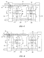
- Figures 9 and 10 show an alternate embodiment of the present invention, with Figure 9 showing the mold closed position and Figure 10 showing the mold open position.
- this embodiment there are three mold support members 104A, 104B and 104C, with each mold support member supporting respective mold plates.
- the previous embodiment used only one such support located centrally on the mold, with support for the second and third sets of mold plates coming from guide or support pins through the top of the mold plates which remained engaged even when the mold was opened.
- the disadvantage of the previously described design is that the secondary mold linkages could further be improved to provide greater access to the open spaces between the mold portions when the mold is in the open position.
- Figures 9 and 10 does not use the long guide or support pins through the top of the mold which can bend or sag with heavy mold portions. Instead, the similar mold support members 104A, 104B and 104C each carry a portion of the mold assembly to locate and guide it during wide opening strokes, as clearly shown in Figures 9 and 10.
- the support members may run on precision alignment features of the molding apparatus, such as the tie bars or machine ways or the like. Separation between the mold portions is provided via linkages or secondary motion means 102 which are connected at one end to the respective mold support members and at the other end to the primary motion means 101.
- link arms 103 insure that the center most portion of the mold remains equidistant between the two machine platens. Additionally, the secondary motion means 102 are caused to move since they are attached to the primary motion means 101. Secondary motion means 102 are designed and positioned such that they will maintain a equal spacing between the open mold portions as shown at Y in Figure 10. In the embodiment of Figures 9 and 10, the pivot point of secondary motion means 102 is halfway between the center pivot point of primary motion means 101 and its extreme pivot point with link arms 103.
- secondary motion means 102 is half the length of link arm 103 and is pivotably attached to the respective mold support members 104B and 104C such that it runs parallel to link arm 103 at all times. This insures that the spacings Y will be equal through the entire mold open movement, if so desired.
- the advantage of this embodiment is the more accessible area between the mold open spacing and a simpler mold movement actuation device with the relatively simple movements of the primary and secondary motion means.
Landscapes
- Engineering & Computer Science (AREA)
- Manufacturing & Machinery (AREA)
- Mechanical Engineering (AREA)
- Moulds For Moulding Plastics Or The Like (AREA)
- Injection Moulding Of Plastics Or The Like (AREA)
Applications Claiming Priority (4)
| Application Number | Priority Date | Filing Date | Title |
|---|---|---|---|
| US23166194A | 1994-04-25 | 1994-04-25 | |
| US231661 | 1994-04-25 | ||
| US08/255,004 US5578333A (en) | 1994-04-25 | 1994-06-07 | Combined mold carrier and linkage apparatus |
| US255004 | 1994-06-07 |
Publications (3)
| Publication Number | Publication Date |
|---|---|
| EP0679492A2 true EP0679492A2 (de) | 1995-11-02 |
| EP0679492A3 EP0679492A3 (de) | 1996-08-07 |
| EP0679492B1 EP0679492B1 (de) | 2000-06-14 |
Family
ID=26925320
Family Applications (1)
| Application Number | Title | Priority Date | Filing Date |
|---|---|---|---|
| EP95810231A Expired - Lifetime EP0679492B1 (de) | 1994-04-25 | 1995-04-07 | Kombinierte Formträger und Gestängevorrichtung |
Country Status (5)
| Country | Link |
|---|---|
| US (2) | US5578333A (de) |
| EP (1) | EP0679492B1 (de) |
| JP (1) | JP2738916B2 (de) |
| AT (1) | ATE193861T1 (de) |
| DE (1) | DE69517467T2 (de) |
Cited By (5)
| Publication number | Priority date | Publication date | Assignee | Title |
|---|---|---|---|---|
| US5908597A (en) * | 1997-04-18 | 1999-06-01 | Husky Injection Molding Systems Ltd. | Ejection methods and linkage apparatus for stack molds |
| EP0911139A3 (de) * | 1997-09-24 | 1999-08-18 | Husky Injection Molding Systems Ltd. | Angusskanal einer Spritzgussform |
| WO2001017745A1 (en) * | 1999-09-08 | 2001-03-15 | Husky Injection Molding Systems Ltd. | Stack mold carrier mounted on linear bearings |
| GB2430641A (en) * | 2005-10-03 | 2007-04-04 | Im Pak Technologies Ltd | Injection compresson impact moulding |
| CN107323749A (zh) * | 2017-06-27 | 2017-11-07 | 广东方振新材料精密组件有限公司 | 多层模板结构及成型机 |
Families Citing this family (36)
| Publication number | Priority date | Publication date | Assignee | Title |
|---|---|---|---|---|
| US5772420A (en) * | 1996-12-16 | 1998-06-30 | Holmes; Henry T. | Greaseless mold carrier and alignment system |
| WO1998055300A1 (en) * | 1997-06-04 | 1998-12-10 | National Tool & Manufacturing Co. | Mold plate centralizing system |
| US5976452A (en) * | 1997-11-05 | 1999-11-02 | Owens-Brockway Plastic Products Inc. | Method and apparatus for forming molded plastic articles |
| US6117382A (en) | 1998-02-05 | 2000-09-12 | Micron Technology, Inc. | Method for encasing array packages |
| BR9800139C1 (pt) | 1998-03-23 | 2000-03-14 | Ind Romi S A Ind Romi S A | Desenvolvimento em mecanismo de bloqueio de molde |
| US6099784A (en) * | 1998-04-03 | 2000-08-08 | Husky Injection Molding Systems Ltd. | Stack mold linkage with unequal strokes |
| US6027681A (en) * | 1998-04-03 | 2000-02-22 | Husky Injection Molding Systems Ltd. | Stack mold linkage with unequal strokes |
| US6089852A (en) * | 1998-04-22 | 2000-07-18 | Tradesco Mold Limited | Mold centering arrangement for injection molding apparatus |
| US6106265A (en) * | 1998-07-09 | 2000-08-22 | Von Holdt; John W. | Stack mold centering system |
| US6086355A (en) * | 1998-07-24 | 2000-07-11 | Tradesco Mold Limited | Actuator carriage for stripper mechanism link assembly |
| US6503075B1 (en) | 2000-08-24 | 2003-01-07 | Husky Injection Molding Systems, Ltd. | Stack mold carrier and rotary turret with services provided by a rotary union |
| DE20017737U1 (de) | 2000-10-16 | 2000-12-21 | Braun Formenbau GmbH, 79353 Bahlingen | Etagenwerkzeug zum Spritzgießen von Kunststoffteilen |
| DE10152259A1 (de) * | 2001-10-20 | 2003-05-08 | Contitech Luftfedersyst Gmbh | Heizschlauchlose Fertigung von 3-Faltenbälgen |
| US6918782B2 (en) * | 2003-10-08 | 2005-07-19 | The Siemon Company | Modular plug with locking member |
| US7223088B2 (en) * | 2004-10-15 | 2007-05-29 | Husky Injection Molding Systems Ltd. | Automatic air and water docking system for a molding machine |
| US7125247B2 (en) | 2004-10-15 | 2006-10-24 | Husky Injection Molding Systems Ltd. | Linkage assembly for a multiple level stack mold molding machine |
| US7361012B2 (en) * | 2004-10-15 | 2008-04-22 | Husky Injection Molding Systems Ltd. | Multiple-level stack mold apparatus |
| US7452494B2 (en) * | 2004-10-15 | 2008-11-18 | Husky Injection Molding Systems Ltd. | Method for loading a moldset into a molding machine |
| US7229268B2 (en) * | 2004-10-15 | 2007-06-12 | Husky Injection Molding Systems Ltd. | System for guiding a moldset into a molding machine |
| US7128565B2 (en) * | 2004-10-15 | 2006-10-31 | Husky Injection Molding Systems Ltd. | Three level stack mold machine |
| CA2547475A1 (en) * | 2006-05-23 | 2007-11-23 | Stackteck Systems Ltd. | Cooling arrangement for centering device and spline shaft |
| US20080131547A1 (en) * | 2006-11-30 | 2008-06-05 | Husky Injection Molding Systems Ltd. | External Sprue Bar Position Alignment Apparatus |
| US20080265465A1 (en) * | 2007-04-24 | 2008-10-30 | Husky Injection Molding Systems Ltd. | Apparatus for Injection Compression Molding and Method of Molding Articles |
| US20090028983A1 (en) * | 2007-07-23 | 2009-01-29 | Chih-Yu Chen | Injection mold with a tie bar |
| US20090047376A1 (en) * | 2007-08-16 | 2009-02-19 | Husky Injection Molding Systems Ltd. | Melt Distribution Apparatus |
| US20090047373A1 (en) * | 2007-08-16 | 2009-02-19 | Husky Injection Molding Systems Ltd. | Bridge Runner System |
| US20090047374A1 (en) * | 2007-08-16 | 2009-02-19 | Husky Injection Molding Systems Ltd. | Mold Module |
| US20090092701A1 (en) * | 2007-10-05 | 2009-04-09 | Husky Injection Molding Systems Ltd. | Auxiliary Carriage Combined with an Auxiliary Carriage Actuator and a Multi-Stack Molding Machine Incorporating Same |
| US7665984B2 (en) | 2007-12-14 | 2010-02-23 | Husky Injection Molding Systems Ltd. | Platen-linkage assembly of injection molding system |
| US7665980B2 (en) * | 2008-06-09 | 2010-02-23 | Dme Company Llc | Apparatus for molding |
| AT507717A1 (de) | 2008-12-16 | 2010-07-15 | Engel Austria Gmbh | Schliesseinheit für eine spritzgiessmaschine |
| JP5512161B2 (ja) * | 2009-04-17 | 2014-06-04 | 株式会社青木固研究所 | 二組の型締機構を備えた型締装置 |
| DE102009051934B3 (de) * | 2009-11-04 | 2010-12-23 | Kraussmaffei Technologies Gmbh | Schließeinheit für eine Spritzgießmaschine |
| CH707711A2 (de) | 2013-03-15 | 2014-09-15 | Foboha Gmbh | Haltevorrichtung für einen drehbaren Formmittelteil in einer Spritzgiessvorrichtung. |
| US9339957B2 (en) | 2014-05-07 | 2016-05-17 | Athena Automation Ltd. | Stack mold support structure for an injection molding machine |
| JP6967130B2 (ja) * | 2016-09-21 | 2021-11-17 | 三光合成株式会社 | 賦形成形型及び賦形成形方法 |
Family Cites Families (15)
| Publication number | Priority date | Publication date | Assignee | Title |
|---|---|---|---|---|
| US2586474A (en) * | 1949-03-29 | 1952-02-19 | Baldwin Lima Hamilton Corp | Platen spacing means for presses |
| US2884032A (en) * | 1957-04-15 | 1959-04-28 | Washington Iron Works | Multi-platen hot press |
| US2966183A (en) * | 1958-04-03 | 1960-12-27 | Baldwin Lima Hamilton Corp | Press platen actuating means |
| US3209405A (en) * | 1962-12-20 | 1965-10-05 | Siempelkamp Maschinenfabrik G | Multi-platen press with simultaneous platen closure |
| FR1445664A (fr) * | 1965-06-02 | 1966-07-15 | Plaster | Perfectionnements aux presses à injection |
| US3518724A (en) * | 1967-03-28 | 1970-07-07 | Motala Verkstad Ab | Means for closing and opening multiplaten presses |
| US3659997A (en) * | 1970-03-04 | 1972-05-02 | Husky Mfg Tool Works Ltd | Injection-molding machine with transverse feed |
| US3767352A (en) * | 1971-07-12 | 1973-10-23 | Husky Mfg Tool Works Ltd | Injection mold with unloading mechanism |
| DE2307103B2 (de) * | 1973-02-14 | 1975-06-05 | G. Siempelkamp & Co, 4150 Krefeld | Anlage zum Vulkanisieren eines Fördergurtes |
| US3941548A (en) * | 1974-10-16 | 1976-03-02 | Bruder Robert G | Injection mold assembly |
| US4207051A (en) * | 1979-01-11 | 1980-06-10 | Husky Injection Molding Systems Limited | Stripper mechanism for injection mold |
| US4408981A (en) * | 1982-06-18 | 1983-10-11 | Husky Injection Molding Systems Inc. | Support for an intermediate platen of a stack mold |
| US4718845A (en) * | 1986-04-02 | 1988-01-12 | James Sheffield | Rack and pinion gear stack mold control |
| US4929166A (en) * | 1988-11-21 | 1990-05-29 | Husky Injection Molding Systems Ltd | Support for quick mold changing |
| US5104308A (en) * | 1990-03-08 | 1992-04-14 | Morton Ray H | Mold plate control mechanism for a multiple plate mold |
-
1994
- 1994-06-07 US US08/255,004 patent/US5578333A/en not_active Expired - Lifetime
-
1995
- 1995-04-07 DE DE69517467T patent/DE69517467T2/de not_active Expired - Lifetime
- 1995-04-07 AT AT95810231T patent/ATE193861T1/de active
- 1995-04-07 EP EP95810231A patent/EP0679492B1/de not_active Expired - Lifetime
- 1995-04-25 JP JP7099036A patent/JP2738916B2/ja not_active Expired - Fee Related
- 1995-05-15 US US08/440,643 patent/US5707666A/en not_active Expired - Lifetime
Cited By (6)
| Publication number | Priority date | Publication date | Assignee | Title |
|---|---|---|---|---|
| US5908597A (en) * | 1997-04-18 | 1999-06-01 | Husky Injection Molding Systems Ltd. | Ejection methods and linkage apparatus for stack molds |
| EP0911139A3 (de) * | 1997-09-24 | 1999-08-18 | Husky Injection Molding Systems Ltd. | Angusskanal einer Spritzgussform |
| WO2001017745A1 (en) * | 1999-09-08 | 2001-03-15 | Husky Injection Molding Systems Ltd. | Stack mold carrier mounted on linear bearings |
| AU761788B2 (en) * | 1999-09-08 | 2003-06-12 | Husky Injection Molding Systems Ltd. | Stack mold carrier mounted on linear bearings |
| GB2430641A (en) * | 2005-10-03 | 2007-04-04 | Im Pak Technologies Ltd | Injection compresson impact moulding |
| CN107323749A (zh) * | 2017-06-27 | 2017-11-07 | 广东方振新材料精密组件有限公司 | 多层模板结构及成型机 |
Also Published As
| Publication number | Publication date |
|---|---|
| ATE193861T1 (de) | 2000-06-15 |
| JPH0839624A (ja) | 1996-02-13 |
| DE69517467T2 (de) | 2001-03-08 |
| DE69517467D1 (de) | 2000-07-20 |
| US5578333A (en) | 1996-11-26 |
| JP2738916B2 (ja) | 1998-04-08 |
| EP0679492A3 (de) | 1996-08-07 |
| EP0679492B1 (de) | 2000-06-14 |
| US5707666A (en) | 1998-01-13 |
Similar Documents
| Publication | Publication Date | Title |
|---|---|---|
| EP0679492B1 (de) | Kombinierte Formträger und Gestängevorrichtung | |
| US3973888A (en) | Die closing unit for injection molding machine with molding die having multiple transfer sections | |
| US4929166A (en) | Support for quick mold changing | |
| US8047832B2 (en) | Injection/stretch blow molding machine | |
| US20100051224A1 (en) | Method to move an upper mold in relation to a lower mold in a permanent mold casting machine and the permanent mold casting machine used for the method | |
| US4422843A (en) | Injection stretching blow molding machine | |
| CN1151022C (zh) | 安装在线性轴承上的叠箱铸模承载架 | |
| KR100455527B1 (ko) | 단조프레스용트랜스퍼피더 | |
| JP4050506B2 (ja) | 鍛造プレス | |
| CN212021958U (zh) | 一种自动印刷生产线 | |
| CN108772454B (zh) | 一种方管自动折边主机及其自动折边机 | |
| CN215703719U (zh) | 一种滑块联动机构及塑胶模具 | |
| EP0206914B1 (de) | Spritzstreckblasformmaschine | |
| CN224073113U (zh) | 一种金属件冲压加工装置 | |
| CN223775943U (zh) | 一种调节阀蜡模成型装置 | |
| CN114394411B (zh) | 一种自动静压铸造设备的型板更换方法及静压铸造设备使用的型板避让装置 | |
| CN223465434U (zh) | 一种模具夹持装置 | |
| CN222495152U (zh) | 一种用于注塑机上的托举模装置 | |
| CN224103404U (zh) | 一种高连续二次注塑模具 | |
| CN218535083U (zh) | 一种陶瓷毛胚成型模具 | |
| CN217944173U (zh) | 一种转向器的模架 | |
| CN219805359U (zh) | 一种金属零件压铸模具 | |
| CN109822870A (zh) | 一种热静压成型装置 | |
| CN219746257U (zh) | 一种具备高强度连体式挂臂机构的盖模机 | |
| US3333628A (en) | Die casting apparatus |
Legal Events
| Date | Code | Title | Description |
|---|---|---|---|
| PUAI | Public reference made under article 153(3) epc to a published international application that has entered the european phase |
Free format text: ORIGINAL CODE: 0009012 |
|
| AK | Designated contracting states |
Kind code of ref document: A2 Designated state(s): AT BE CH DE DK ES FR GB IT LI NL SE |
|
| RIN1 | Information on inventor provided before grant (corrected) |
Inventor name: SCHAD, ROBERT D. Inventor name: DI SIMONE, JOHN |
|
| PUAL | Search report despatched |
Free format text: ORIGINAL CODE: 0009013 |
|
| AK | Designated contracting states |
Kind code of ref document: A3 Designated state(s): AT BE CH DE DK ES FR GB IT LI NL SE |
|
| 17P | Request for examination filed |
Effective date: 19960816 |
|
| 17Q | First examination report despatched |
Effective date: 19981230 |
|
| GRAG | Despatch of communication of intention to grant |
Free format text: ORIGINAL CODE: EPIDOS AGRA |
|
| GRAG | Despatch of communication of intention to grant |
Free format text: ORIGINAL CODE: EPIDOS AGRA |
|
| GRAH | Despatch of communication of intention to grant a patent |
Free format text: ORIGINAL CODE: EPIDOS IGRA |
|
| GRAH | Despatch of communication of intention to grant a patent |
Free format text: ORIGINAL CODE: EPIDOS IGRA |
|
| GRAA | (expected) grant |
Free format text: ORIGINAL CODE: 0009210 |
|
| AK | Designated contracting states |
Kind code of ref document: B1 Designated state(s): AT BE CH DE DK ES FR GB IT LI NL SE |
|
| PG25 | Lapsed in a contracting state [announced via postgrant information from national office to epo] |
Ref country code: FR Free format text: LAPSE BECAUSE OF FAILURE TO SUBMIT A TRANSLATION OF THE DESCRIPTION OR TO PAY THE FEE WITHIN THE PRESCRIBED TIME-LIMIT Effective date: 20000614 Ref country code: ES Free format text: THE PATENT HAS BEEN ANNULLED BY A DECISION OF A NATIONAL AUTHORITY Effective date: 20000614 Ref country code: BE Free format text: LAPSE BECAUSE OF FAILURE TO SUBMIT A TRANSLATION OF THE DESCRIPTION OR TO PAY THE FEE WITHIN THE PRESCRIBED TIME-LIMIT Effective date: 20000614 |
|
| REF | Corresponds to: |
Ref document number: 193861 Country of ref document: AT Date of ref document: 20000615 Kind code of ref document: T |
|
| REG | Reference to a national code |
Ref country code: CH Ref legal event code: EP |
|
| REG | Reference to a national code |
Ref country code: CH Ref legal event code: NV Representative=s name: PATENTANWAELTE BREITER + WIEDMER AG |
|
| REF | Corresponds to: |
Ref document number: 69517467 Country of ref document: DE Date of ref document: 20000720 |
|
| ITF | It: translation for a ep patent filed | ||
| PG25 | Lapsed in a contracting state [announced via postgrant information from national office to epo] |
Ref country code: SE Free format text: LAPSE BECAUSE OF FAILURE TO SUBMIT A TRANSLATION OF THE DESCRIPTION OR TO PAY THE FEE WITHIN THE PRESCRIBED TIME-LIMIT Effective date: 20000914 Ref country code: DK Free format text: LAPSE BECAUSE OF FAILURE TO SUBMIT A TRANSLATION OF THE DESCRIPTION OR TO PAY THE FEE WITHIN THE PRESCRIBED TIME-LIMIT Effective date: 20000914 |
|
| EN | Fr: translation not filed | ||
| PG25 | Lapsed in a contracting state [announced via postgrant information from national office to epo] |
Ref country code: GB Free format text: LAPSE BECAUSE OF NON-PAYMENT OF DUE FEES Effective date: 20010407 |
|
| PLBE | No opposition filed within time limit |
Free format text: ORIGINAL CODE: 0009261 |
|
| STAA | Information on the status of an ep patent application or granted ep patent |
Free format text: STATUS: NO OPPOSITION FILED WITHIN TIME LIMIT |
|
| 26N | No opposition filed | ||
| GBPC | Gb: european patent ceased through non-payment of renewal fee |
Effective date: 20010407 |
|
| REG | Reference to a national code |
Ref country code: CH Ref legal event code: NV Representative=s name: BOVARD AG PATENTANWAELTE |
|
| REG | Reference to a national code |
Ref country code: CH Ref legal event code: PFA Owner name: HUSKY INJECTION MOLDING SYSTEMS LTD. Free format text: HUSKY INJECTION MOLDING SYSTEMS LTD.#500 QUEEN STREET SOUTH#BOLTON ONTARIO L7E 5S5 (CA) -TRANSFER TO- HUSKY INJECTION MOLDING SYSTEMS LTD.#500 QUEEN STREET SOUTH#BOLTON ONTARIO L7E 5S5 (CA) |
|
| PGFP | Annual fee paid to national office [announced via postgrant information from national office to epo] |
Ref country code: NL Payment date: 20110316 Year of fee payment: 17 |
|
| PGFP | Annual fee paid to national office [announced via postgrant information from national office to epo] |
Ref country code: DE Payment date: 20110309 Year of fee payment: 17 |
|
| PGFP | Annual fee paid to national office [announced via postgrant information from national office to epo] |
Ref country code: AT Payment date: 20110309 Year of fee payment: 17 |
|
| PGFP | Annual fee paid to national office [announced via postgrant information from national office to epo] |
Ref country code: IT Payment date: 20110413 Year of fee payment: 17 |
|
| PGFP | Annual fee paid to national office [announced via postgrant information from national office to epo] |
Ref country code: CH Payment date: 20120321 Year of fee payment: 18 |
|
| REG | Reference to a national code |
Ref country code: NL Ref legal event code: V1 Effective date: 20121101 |
|
| REG | Reference to a national code |
Ref country code: AT Ref legal event code: MM01 Ref document number: 193861 Country of ref document: AT Kind code of ref document: T Effective date: 20120407 |
|
| PG25 | Lapsed in a contracting state [announced via postgrant information from national office to epo] |
Ref country code: AT Free format text: LAPSE BECAUSE OF NON-PAYMENT OF DUE FEES Effective date: 20120407 |
|
| REG | Reference to a national code |
Ref country code: DE Ref legal event code: R119 Ref document number: 69517467 Country of ref document: DE Effective date: 20121101 |
|
| PG25 | Lapsed in a contracting state [announced via postgrant information from national office to epo] |
Ref country code: IT Free format text: LAPSE BECAUSE OF NON-PAYMENT OF DUE FEES Effective date: 20120407 |
|
| PG25 | Lapsed in a contracting state [announced via postgrant information from national office to epo] |
Ref country code: NL Free format text: LAPSE BECAUSE OF NON-PAYMENT OF DUE FEES Effective date: 20121101 |
|
| REG | Reference to a national code |
Ref country code: CH Ref legal event code: PL |
|
| PG25 | Lapsed in a contracting state [announced via postgrant information from national office to epo] |
Ref country code: CH Free format text: LAPSE BECAUSE OF NON-PAYMENT OF DUE FEES Effective date: 20130430 Ref country code: LI Free format text: LAPSE BECAUSE OF NON-PAYMENT OF DUE FEES Effective date: 20130430 |
|
| PG25 | Lapsed in a contracting state [announced via postgrant information from national office to epo] |
Ref country code: DE Free format text: LAPSE BECAUSE OF NON-PAYMENT OF DUE FEES Effective date: 20121101 |