EP0681087A2 - Système de bouchon temporaire pour conduites de puits - Google Patents
Système de bouchon temporaire pour conduites de puits Download PDFInfo
- Publication number
- EP0681087A2 EP0681087A2 EP95303024A EP95303024A EP0681087A2 EP 0681087 A2 EP0681087 A2 EP 0681087A2 EP 95303024 A EP95303024 A EP 95303024A EP 95303024 A EP95303024 A EP 95303024A EP 0681087 A2 EP0681087 A2 EP 0681087A2
- Authority
- EP
- European Patent Office
- Prior art keywords
- plug
- well
- fluid
- housing
- temporary
- Prior art date
- Legal status (The legal status is an assumption and is not a legal conclusion. Google has not performed a legal analysis and makes no representation as to the accuracy of the status listed.)
- Granted
Links
Images


Classifications
-
- E—FIXED CONSTRUCTIONS
- E21—EARTH OR ROCK DRILLING; MINING
- E21B—EARTH OR ROCK DRILLING; OBTAINING OIL, GAS, WATER, SOLUBLE OR MELTABLE MATERIALS OR A SLURRY OF MINERALS FROM WELLS
- E21B23/00—Apparatus for displacing, setting, locking, releasing or removing tools, packers or the like in boreholes or wells
- E21B23/004—Indexing systems for guiding relative movement between telescoping parts of downhole tools
- E21B23/006—"J-slot" systems, i.e. lug and slot indexing mechanisms
-
- E—FIXED CONSTRUCTIONS
- E21—EARTH OR ROCK DRILLING; MINING
- E21B—EARTH OR ROCK DRILLING; OBTAINING OIL, GAS, WATER, SOLUBLE OR MELTABLE MATERIALS OR A SLURRY OF MINERALS FROM WELLS
- E21B23/00—Apparatus for displacing, setting, locking, releasing or removing tools, packers or the like in boreholes or wells
- E21B23/04—Apparatus for displacing, setting, locking, releasing or removing tools, packers or the like in boreholes or wells operated by fluid means, e.g. actuated by explosion
- E21B23/042—Apparatus for displacing, setting, locking, releasing or removing tools, packers or the like in boreholes or wells operated by fluid means, e.g. actuated by explosion using a single piston or multiple mechanically interconnected pistons
-
- E—FIXED CONSTRUCTIONS
- E21—EARTH OR ROCK DRILLING; MINING
- E21B—EARTH OR ROCK DRILLING; OBTAINING OIL, GAS, WATER, SOLUBLE OR MELTABLE MATERIALS OR A SLURRY OF MINERALS FROM WELLS
- E21B33/00—Sealing or packing boreholes or wells
- E21B33/10—Sealing or packing boreholes or wells in the borehole
- E21B33/12—Packers; Plugs
-
- E—FIXED CONSTRUCTIONS
- E21—EARTH OR ROCK DRILLING; MINING
- E21B—EARTH OR ROCK DRILLING; OBTAINING OIL, GAS, WATER, SOLUBLE OR MELTABLE MATERIALS OR A SLURRY OF MINERALS FROM WELLS
- E21B33/00—Sealing or packing boreholes or wells
- E21B33/10—Sealing or packing boreholes or wells in the borehole
- E21B33/13—Methods or devices for cementing, for plugging holes, crevices or the like
- E21B33/134—Bridging plugs
-
- E—FIXED CONSTRUCTIONS
- E21—EARTH OR ROCK DRILLING; MINING
- E21B—EARTH OR ROCK DRILLING; OBTAINING OIL, GAS, WATER, SOLUBLE OR MELTABLE MATERIALS OR A SLURRY OF MINERALS FROM WELLS
- E21B34/00—Valve arrangements for boreholes or wells
- E21B34/06—Valve arrangements for boreholes or wells in wells
- E21B34/063—Valve or closure with destructible element, e.g. frangible disc
-
- E—FIXED CONSTRUCTIONS
- E21—EARTH OR ROCK DRILLING; MINING
- E21B—EARTH OR ROCK DRILLING; OBTAINING OIL, GAS, WATER, SOLUBLE OR MELTABLE MATERIALS OR A SLURRY OF MINERALS FROM WELLS
- E21B34/00—Valve arrangements for boreholes or wells
- E21B34/06—Valve arrangements for boreholes or wells in wells
- E21B34/10—Valve arrangements for boreholes or wells in wells operated by control fluid supplied from outside the borehole
- E21B34/102—Valve arrangements for boreholes or wells in wells operated by control fluid supplied from outside the borehole with means for locking the closing element in open or closed position
Definitions
- This invention relates to a method and apparatus for temporarily closing a subterranean fluid conducting conduit.
- plugs In conventional practice, when a well conduit is desired to be temporarily closed off, it is common to set a plug within the conduit to preclude the flow of fluids at the preferred location.
- oil and gas wells there are many types of plugs that are used for different applications.
- removable plugs typically used during cementing procedures that are made of soft metals that may be drilled out of the conduit after use. Plugs that may be removed from a well intact are referred to as "retrievable" plugs. Removal, however, requires mechanical intervention from the surface of the well. Common intervention techniques include re-entry into the well with wireline, coiled tubing, or tubing string.
- any tools that have been associated with the plug during its use must be removed or "pulled" from the well to provide access to the plug for the removal process.
- the pulling of tools and removal of the plug to re-establish flow within a downhole conduit often entails significant cost and rig downtime. It is, therefore, desirable to develop a plug which may be readily removed or destroyed without either significant expense or rig downtime.
- Known conduit plugs incorporating frangible elements that must be broken from their plugging positions include frangible disks that are stationarily located within tubular housings and flapper type elements. Breakage may be initiated by piercing the plug to cause destructive stresses within the plug's body, mechanically impacting and shattering the plug, or increasing the pressure differential across the plug until the plug is "blown" from its seat. After breakage has occurred, the resulting shards or pieces must be washed out of the well bore with completion fluid or the like in many situations. Because most known designs call for a relatively flat plug to be supported about its periphery, the plug commonly breaks from the interior outwardly and into relatively large pieces.
- a temporary plug be set within a conduit, usually the tubing string or well casing, but it may also be tubular components associated with downhole tools being used in the well.
- An example of such a downhole tool is a pressure set packer.
- the packer assembly will have a tail-pipe extending below the pack off elements.
- a temporary plug will have been installed in the tail-pipe before the packer is placed within the well or will be installed during the setting process.
- Frangible plugs described hereinabove may be used to plug the tail-pipe.
- Alternative plug means may include a wireline disposed plug, a wireline disposed dart, or a seated ball.
- the plugging structure be removed in order to establish a passage way through the packer assembly.
- a frangible plug in the packer must be mechanically broken from its seat.
- sufficient pressure must be applied above the packer to expel the ball into the well beyond the packer assembly.
- a common detriment of either the destroyed frangible member or the expelled ball is that potentially fouling debris remains in the well.
- the debris' significance increases in non-vertical wells because it may remain relatively localized at the location of dislodgment where continuing well activity and operations may take place, or at least pass in the future.
- the debris may also be carried upward in the well fouling equipment along the way or surface equipment at the top of the well. This should be contrasted to vertical wells where the debris is more likely to fall clear of working mechanisms, but may also create fouling problems.
- apparatus for temporarily closing a subterranean fluid conducting conduit which apparatus comprises a tubular housing to be disposed within the fluid of a subterranean well; a temporary plug positioned within said housing for blocking fluid passage through said housing; a mechanical fracturing means for breaking said temporary plug so that fluid flow through said housing is permitted; said temporary plug being constructed at least partially from material dissolvable in the well fluid.
- the plug apparatus and method of the invention can be used in any size conduit.
- the dimensions of the plug will be dependent upon the area to be plugged and the service conditions into which it will be placed. Degradation and removal of the plug is accomplished without mechanical intervention from the well's surface. Furthermore, the resulting debris or "fall out” from the removed plug preferably comprises sufficiently small particles that are easily transported by the fluids of the well without blocking or fouling other aspects and equipment of the well.
- the plug has a radial edge which is vulnerable to the application of non-uniform shearing forces.
- the plug may be destroyed through application of increased pressure upon the housing carrying the plug that actuates a plug rupture mechanism which in turn destroys the integrity of the plug proximate its radial edge. This allows the plug to be substantially eliminated from the blocked conduit within a short period of time thereafter.
- the plug is comprised of a salt and sand mixture which is highly resistant to fluid compressive forces but is subject to destruction under non-uniform shear forces proximate the radial edge and tensile forces at any location.
- the plug is preferably encased within a plug sleeve.
- the sleeve is then encased within a plug housing which may be disposed within the well bore.
- the sleeve is associated with the housing so that fluid may be displaced about the plug sleeve as the housing is disposed into the well bore. In this capacity, the plug allows the well fluids to pass therethrough and fill the tubing above the plug during disposal into the well.
- the plug sleeve When the plug has reached the desired location within the wellbore, the plug sleeve is positioned within the housing so that fluid flow is blocked. This is considered to be a "check" position because the plug is blocking fluid flow in one direction (downward) in this position while it would permit flow in the other direction (upward).
- An annular shear member presenting a point stress portion is contained within the plug sleeve and detachably connected thereto. When required, the shear member is released from the surrounding plug sleeve and the point stress portion forced against the radial edge plug to substantially destroy the plug structure.
- the plug material is substantially dissolvable within the well bore fluids to permit re-establishment of fluid flow therethrough and operations within the well bore shortly thereafter.
- the plug assembly includes a tubular housing disposed within the fluid of a subterranean well. There is a temporary plug positioned within the housing for blocking fluid passage through that housing. Also positioned within the housing is a mechanical fracturing means for breaking the temporary plug so that fluid flow through the housing is permitted.
- the temporary plug is constructed at least partially from material that is dissolvable in the well fluid.
- the dissolvable portion of the temporary plug includes an aggregate and binder that are solidified into a substantially rigid frangible member that is the plug body.
- the binder dissolves in the well fluid
- the individual pieces of aggregate are released one from the other.
- the time required to dissolve the binding material is hastened because the aggregate falls away from the binder thereby exposing increased amounts of surface area of the binder to the dissolving well fluids.
- the size of the aggregate is such that each particle is sufficiently small so that it will not impede other operations performed within the well after the plug deteriorates. It is contemplated that the aggregate may also be dissolvable in the well fluids. The speed with which the aggregate dissolves in the well fluid would, however, differ from the time it take the binder to dissolve.
- the aggregate is sand particles and the binder is salt.
- the binder is salt.
- the temporary plug is at least partially contained within a dissolving resistant encasement composed of substantially pure binder.
- a means for piercing the encasement to allow the well fluid access to the interior of said temporary plug may be provided.
- a method for utilizing the above described temporary plug will include installing a temporary frangible plug within a housing located within a fluid conducting conduit and then disposing that housing into a well so that the plug is submerged in well fluid. The temporary plug is then fractured so that it breaks into pieces that are unsupportable within the housing and subsequently permits fluid flow through the housing. The plug is then dissolved into particles small enough that will not foul future operations within the well.
- the temporary plug has an interior core of unbound aggregate contained within a flexible membrane.
- the aggregate is vacuum packed within the membrane so that the temporary plug is substantially rigid while the vacuum is maintained within the membrane.
- a means for piercing said membrane is provided that opens an avenue for allowing the well fluid access to the interior of the temporary plug.
- a corresponding method of utilizing this embodiment includes installing the temporary plug within the housing that is located within a fluid conducting conduit. The housing is then disposed into a fluid filled well so that the plug is submerged. The membrane is then pierced so that the vacuum pressure (differential across the membrane) is balanced to allow the previously substantially rigid plug to collapse and become unsupportable within the housing. As a result, fluid flow is similarly permitted through the housing. After collapse, the loose aggregate is released from the membrane and removed away from the housing by the well fluid.
- Still another embodiment has a temporary plug supported within a housing at a periphery of the plug.
- the plug is substantially spherically dome shaped. Due to this shape, the forces experienced in the plug are almost exclusively compressive in nature. This may be contrasted with known frangible disks which are flat and vulnerable to breakage because of the tensile and shear stresses induced during operation. In a flat frangible disk, great tensile forces may be experienced on the lower face of the plug body that is away from the applied pressure while great shear forces are experienced about the periphery of the disk at the points where the edge of the disk bears upon the support structure. In combination, these stresses compromise the integrity of the flat disk's operation.
- the invention disclosed herein includes a frangible plug for disposal in a well bore to block fluid flow therethrough.
- the plug has a radial edge and is substantially rupturable upon the application of non-uniform shear forces proximate the edge of the plug. After rupture, the plug is substantially eliminated from the well bore by dissolving the resultant pieces in the well fluids.
- a method for employing the plug will include disposing the frangible plug within a well bore to block fluid flow therethrough. After use, the plug is then disposed of by using a plug rupture mechanism proximate the plug which is actuatable by the introduction of increased pressure within the plugged conduit.
- the plug rupture mechanism comprises a pair of nested radial support members which are selectively separable to alter radial support of the plug thereby rendering the plug vulnerable to substantial destruction by well bore pressure.
- the plug is comprised of vacuum packed aggregate within a flexible encasement or made of a ceramic or glass material or of liquid soluble metals.
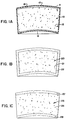
- FIGS. 1A to 1C depict alternative embodiments of an exemplary plug constructed in accordance with the present invention.
- Figure 2A depicts an embodiment of a plug assembly constructed in accordance with the present invention during disposal within a well bore.
- Figure 2B depicts an embodiment of a plug assembly constructed in accordance with the present invention with the plug set against fluid flow.
- Figure 2C depicts an example of destruction of the plug by a shear member.
- FIGURE 3 depicts an alternative embodiment of plug assembly wherein the plug is comprised of a domed glass or ceramic material.
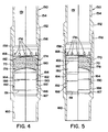
- FIGURE 4 and 5 depict an embodiment in which selective well fluid access is provided by breaking the sleeve in which the plug body is carried.
- an exemplary, temporary plug 10 having a convex upper side 11 and concave lower side 12, as well as an upwardly, outwardly angled vertical, conical surface 13.
- the interior portion of the plug 10 may be comprised of any material, or combinations of materials, that will either dissolve into the well fluids or break down into particles sufficiently small that those particles do not foul other components of the well or services performed therein. It is anticipated that the plug 10 will typically be comprised of a small aggregate and a binder material. The binder will usually be dissolvable in the well fluids and the aggregate will be small enough that it becomes suspended in the well fluids for transport therewith.
- an acceptable binder is salt and an example of an acceptable aggregate is sand.
- sand in the plug's 10 composition assists the breakdown of the plug material in the well fluid after the initial integrity of the plug 10 is mechanically destroyed.
- the sand increases the porosity and permeability of the plug 10, thereby providing greater surface area upon which the dissolving forces of the fluid can act.
- plug 10 is comprised of a salt and sand mixture.
- the sand is very fine and has substantially no particles larger than 1 millimeter in diameter.
- the salt may be of the granulated "table salt” variety. The exact proportions of sand to salt are not critical; a mixture of approximately 50% of each by weight has been found to be acceptable. A small amount of liquid is added to the mixture so that a plug 10 may be formed by densifying and solidifying the constituent materials under pressure and heat.
- the plug 10 is formed in an appropriately shaped mold to which the pressure and heat are applied.
- the temperature must be sufficient to drive off the moisture in the sand and salt mixture.
- the resulting molded plug 10 should be capable of enduring compressive forces on the order of 20 MPa (3000 psi) and temperatures of 100°C.
- the plug should also have been sufficiently compressed so that it resists vibrations experienced within the well environment.
- the surface areas of the plug 10 that are exposed to well fluid are sealed.
- the plug 10 should be sufficiently brittle to be vulnerable to shear destructive forces such as upon the application of a point stress of a selected magnitude.
- the plug 10 is oriented to contain those pressures while minimizing the amount of tensile stress experienced within the body of the plug 10. It is anticipated, however, that the plug 10 could be oriented to contain pressures from below, or any other direction. Therefore, in the exemplary illustrations the plug is upwardly arced shaped to provide optimum resistance against downwardly acting fluid compressive forces in a well bore. It is noted that in the preferred embodiment of FIG. 1A, the arc of concave surface 12 would correspond roughly to a segment of a smaller sphere than that to which the arc of convex surface 11 corresponds. Surface 13 is preferably angled outwardly in a conical shape. It should be appreciated, however, that the dimensions of the plug 10 are governed by the distance it must span to plug a particular conduit, and therefore are variable.
- the integrity of the salt and sand plug 10 just described may be improved by the application of a thin protective fluid impermeable coating 15, such as epoxy, upon surfaces 11 and 12 to seal the plug surface against the well fluid.
- a thin protective fluid impermeable coating 15, such as epoxy upon surfaces 11 and 12 to seal the plug surface against the well fluid.
- portions of the exterior of the plug 10 may be encased in a flexible sheath or encasement 17 for protection against the well bore fluids. Neoprene rubber or other soft rubbers are suitable for constructing the encasement 17.
- the plug material within the encasement 17 may be only sand which is vacuum packed therein.
- the vacuum pressure within the encasement 17, having a magnitude of approximately one atmosphere, will maintain the sand grains in dense engagement with each other to prevent relative motion therebetween. It should be understood that the relative pressure upon the encased material will increase as the plug 10 is disposed further into the well due to hydrostatic pressure. Therefore, during operation, the vacuum pressure applied to the aggregate will be equal to the hydrostatic pressure, plus one atmosphere.
- the encasement 17 is punctured or otherwise ruptured causing the contained sand to be liberated and the encasement to collapse.
- the sheath or encasement 17 will break into several pieces. Therefore, the sheath 17 should be thin enough so that resulting pieces do not present impedances to tools disposed within the well bore following destruction of the plug. Still further, the encasement 17 may be constructed from a material that will eventually dissolve in the well fluids, but not within the expected service time of the plug 10.
- FIG. 1B an alternative embodiment of a plug 20 is shown which is shaped substantially the same as plug 10.
- Plug 20 contains a central portion 21 which may be comprised of a sand/salt mixture as previously described.
- An outer crust 22 is formed around the central portion 21.
- FIG. 1C illustrates a variation on plug 20 in which caps 27 and 28 are constructed similarly to the crust 22.
- the crust 22 may be comprised of substantially 100% binder which is compressed and heated to be formed integrally with the central portion 21 of the plug 20.
- salt has been utilized as the crust 22. Testing has shown that plug material formed substantially of all salt is more resistant to compressive forces and degradation from well bore fluids than plug material of a salt/sand mixture.
- a crusted combination as illustrated provides a stronger plug that initially retains its rigid form but subsequently breaks down quickly once the crust erodes allowing well fluid into the central portion.
- the thickness of the crust 22 will be governed by the desired time period before the soluble crust is sufficiently dissolved to expose a portion of the central portion 21, following which destruction of the plug occurs rapidly.
- an exemplary plug assembly 50 which includes an outer plug housing 52 which is substantially tubular in shape and adapted to be connected in a tubing string (conduit) disposed within a well bore in which a temporary plug is desired.
- the housing 52 includes an upper section 53 threadedly connected at joint 57 to a lower section 55.
- Upper section 53 has a radially enlarged bore section 54 having a downwardly facing, inward frusto-conical shoulder 56 and the upper terminal end of lower section 55 forms an upwardly facing, frusto-conical sealing shoulder 58.
- Upwardly facing sealing shoulder 58 is preferably angled inwardly at an approximate angle of 45°.
- a plug sleeve 60 having an upper longitudinal end 62 adapted to contact the upper inwardly disposed annular shoulder 56 of the housing 52.
- Fluid flow ports 64 are disposed about the circumference of the sleeve 60 proximate upper end 62.
- Sleeve 60 also forms a tapered conical section 66 which is downwardly, inwardly tapered and disposed below the flow ports 64.
- a radially expanded section 68 is disposed below the conical section 66 and forms an annular bearing portion 69 between sections 66, 68.
- Downward shoulder 75 is disposed about the interior circumference of sleeve 60.
- a frangible plug 70 which may be of any one of the types described or depicted with respect to FIG. 1A-1C.
- the plug 70 is preferably tightly received within the conical section 66.
- the plug 70 may be formed and prestressed within the tapered section to afford it greater strength against liquid compression forces while disposed within a well bore.
- the plug may be formed separately and pressed and bonded into the sleeve with a suitable sealing glue compound, such as rubber cement or the like. In any event, the interior central portion of the plug will be shielded from the well fluid.
- An annular shear member 72 is disposed within the sleeve 60 and features an upper reduced diameter portion 61 forming an outwardly facing annular shoulder 74 which is received within the radially expanded section 68 of the sleeve 60.
- the upper terminal end of member 72 is supported by bearing portion 69.
- One or more elastomeric seals 76 may be used to seal the connection between shear member 72 and the sleeve 60.
- a shear ring 78 detachably connects the sleeve 60 to the shear member 72.
- Shear member 72 presents a point stress portion 80 directed toward the plug 70.
- the point stress portion comprises an arcuate support shoulder 81 located proximate a portion of the bottom radial edge of plug 70 and an arcuate tapering non-supporting shoulder 83 which tapers downwardly from support shoulder 81 and away from the bottom of plug 70.
- Shear member 72 presents a lower annular frusto-conical shoulder 82 adapted to sealingly engage shoulder 58.
- the shear ring 78 will preferably require a preselected shear force to shear and release shear member 72 from sleeve 60.
- a lock wire 84 is disposed about the inner circumference of the enlarged bore section 54.
- the plug assembly 50 is assembled substantially as shown in FIG. 2A during running of the plug assembly 50 into a well bore. Fluid is displaced around the plug 70 as the plug assembly 50 is disposed into the well bore. The resistance presented by the fluid in the well causes plug 70, shear member 72 and sleeve 60 to be carried in an upper most position during downward travel through the fluid. In the upper position, fluid from below flows between shoulders 82 and shoulder 58, into the annular area 89 formed by sleeve 60 and housing 52, and ultimately through flow ports 64 upwardly into flow bore 91.
- plug assembly 50 When the plug assembly 50 has been disposed to the proper depth within the well bore, fluid pressure is applied to the top of the plug 70 causing the plug 70, shear member 72 and sleeve 60 to shift downwardly, as illustrated in FIG. 2B such that sleeve 60 moves downwardly within housing 52 until shoulder 82 meets and seals against shoulder 58, thereby establishing a metal-to-metal seal against fluid flow. In this position, the plug assembly 50 seals against fluid transfer across the plug 70.
- FIG. 2C illustrates this operation.
- the fluid pressure on top of the plug 70 and sleeve 60 causes plug 70 and sleeve 60 to snap downward within housing 52 since sleeve 60 is no longer supported by shear ring 78.
- the plug 70 is then forced downwardly against the arcuate support shoulder 81 of point stress portion 80 of shear member 72 that acts as a plug rupture mechanism.
- Point stress portion 80 applies non-uniform shearing forces proximate the radial edge of plug 70.
- the non-uniform shear forces applied by the shear member 72 are sufficient to pierce any protective coating or encasement that may be present and then break the frangible plug 70 into pieces. Downward movement of the sleeve 60 with respect to shear member 72 will ultimately be limited by the engagement of opposing shoulders.
- Lock wire 84 maintains housing 52 and sleeve 60 in non-sliding engagement after the sleeve 60 has moved downward.
- FIG. 3 depicts an alternative embodiment of the present invention featuring a plug assembly 100 having a plug 102 made of rigid and brittle material such as glass or ceramics.
- the ceramic or glass plug 102 may take a form different from that of the plugs previously described, but have similar effectiveness as a fluid barrier.
- Plug 102 may be considerably thinner than the sand and salt type plugs described earlier and be substantially dome shaped with the radii of curvature of upper and lower surfaces 104 and 105 being roughly the same.
- Plug assembly 100 includes an upper housing 106 and lower housing 108 which form a flow bore 109 therethrough.
- the upper and lower housing 106 and 108 are threadedly connected at 110 to form a radially enlarged bore section 112.
- Plug 102 is disposed in a fixed relation within upper housing section 106 so as to block fluid flow through fluid flow bore 109; by orienting the plug 102 so that the convex portion of the dome is upwardly facing, a greater fluid force may be resisted for above the plug 102. Fluid flow will, however, be blocked in both directions.
- An upper piston 114 radially surrounds and contacts the outer edges of upper surface 104 of plug 102. O-rings 116 and 118 ensure a fluid tight seal between the plug 102 and the piston 114.
- Plug 102 is supported radially by outer support member 120 and inner support member 122 which is nested therewithin.
- Inner support member 122 is an annularly shaped ring-type member having a number of slots 124 cut into its upper portion. It also presents inwardly facing upper arcuate shoulders 126 upon which the radial edges of plug 102 are seated.
- Outer support member 120 is also an annularly shaped, ring-type structure which surrounds inner support member 122 and presents inwardly projecting protuberances which reside within slots 124 when inner support member 122 is nested within outer support member 120.
- Sleeve 130 supports the outer and inner support members 120 and 122.
- Sleeve 130 is detachably connected to ring 132 by means of a shear wire or other shear mechanism 134. Ring 132 is seated on shear member 136 which abuts the lower housing 108.
- the plug 102 will resist downward compression through flow bore 109 as the glass or ceramic structure of plug 102 will be predominantly stressed by relatively uniform compressive forces since the edges of the plug 102 are firmly supported between the piston 114 above and the inner and outer support members 120 and 122 below.
- plug 102 breaks into a number of small pieces as a result of the stress patterns. Once ruptured, the pieces of plug 102 should be sufficiently small so as not to foul other operations subsequently performed within the well. As a result, the plug 102 is substantially eliminated from the wellbore.
- a water soluble metal may be used to construct the plug 102. After physical destruction of the metal plug, the well bore fluids dissolve the plug fragments within a short time thereafter.
- FIG. 4 A further exemplary embodiment of the present invention is shown in Figures 4 and 5.
- the plug rupture mechanism provides selective well fluid access to portions of the radial edge of the plug 70 which are readily degradable by fluid contact. It is noted that plugs which are suitable for use in plug assemblies of this type are those constructed similar to or shown in Figure 1A-C.
- Figures 4 and 5 illustrate cross-sectional views of an exemplary plug assembly 150.
- the figures present juxtaposed halves of the tool in different stages of operation.
- the right half of Figure 4 illustrates the assembly 150 as it would appear while being disposed downwardly within the well bore and permitting fluid flow upwardly around the plug 70.
- the left half of Figure 4 shows the plug assembly 150 set for fluid flow blockage.
- the right half of Figure 5 shows the plug assembly 150 after initial plug rupture.
- the left half of Figure 5 illustrates the configuration of the assembly 150 following substantial destruction of the plug 70.
- the assembly 150 includes an upper adaptor 152 with upper threads or other connector means 154 which permit the assembly 150 to be incorporated within a conduit.
- Upper adaptor 152 is connected at thread 156 to plug housing 158.
- Plug housing 158 includes lower adaptor threads 160 for connection with other portions of a conduit.
- a central portion of housing 158 includes sleeve bore 162 having inner upward facing shoulders 164, 166 and 167.
- annular ring 172 Above sleeve bore 162 is radially expanded fluid flow bore 168 which presents an annular upward facing shoulder 170.
- Annular ring 172 is disposed proximate fluid flow bore 168 within the housing 158 and features an annular lower shoulder 174 which is adapted to be generally complimentary to shoulder 170. It is preferred that shoulders 170 and 174 do not form a seal, but, when engaged, will permit fluid flow therebetween.
- Ring 172 features a number of lateral ports 176 about its periphery.
- Sleeve bore 162 contains a sleeve 178 which is slideably received therein.
- Sleeve 178 presents an outwardly tapered plug support section 180 with an upper ring contacting portion 182.
- the outer radial surface of sleeve 178 presents a downwardly facing shoulder 184.
- the sleeve also presents a lower edge 186 which is complimentary to seat 188 of sleeve support member 190.
- Sleeve support member 190 is shear pinned at 192 to plug housing 158 and features lower edge 191.
- assembly 150 permits fluid flow around the plug sleeve 178 in a manner similar to that described with respect to previous embodiments and as shown in the right side of Figure 4.
- plug sleeve 178 When disposed within a well bore for blockage of fluid flow therethrough as illustrated in the left half of Figure 4, plug sleeve 178 is moved downwardly within bore 162 until lower edge 186 contacts seat 188 to form a seal against fluid flow therethrough. In this portion, little or no fluid flow is permitted between shoulder 174 and ring contacting portion 182 toward portions of plug 70.
- sleeve 178 Upon application of increased pressure within the well bore 151, sleeve 178 is shifted downward as shown in the right half of Figure 5 until downward facing shoulder 184 of the sleeve 178 contacts shoulder 164. Upward facing shoulder 166 may also act to limit downward movement of sleeve support member 190 and edge 191 will ultimately be limited from excessive downward movement by shoulder 167.
- pressurized fluid within well bore 151 passes through ports 176 outward into radially enlarged fluid flow bore 168 and between shoulders 170 and 174. Due to the separation of ring contacting portion 182 and shoulder 174, fluid is permitted to contact plug 70 proximate its upper radial edge to begin dissolution of the plug 70 as previously described. After a period of time, plug 70 dissolves as shown in the left half of the Figure 5.
Landscapes
- Geology (AREA)
- Life Sciences & Earth Sciences (AREA)
- Engineering & Computer Science (AREA)
- Mining & Mineral Resources (AREA)
- Environmental & Geological Engineering (AREA)
- Fluid Mechanics (AREA)
- Physics & Mathematics (AREA)
- General Life Sciences & Earth Sciences (AREA)
- Geochemistry & Mineralogy (AREA)
- Pipe Accessories (AREA)
- Pressure Vessels And Lids Thereof (AREA)
- Treatment Of Liquids With Adsorbents In General (AREA)
- Prostheses (AREA)
- Respiratory Apparatuses And Protective Means (AREA)
Applications Claiming Priority (2)
| Application Number | Priority Date | Filing Date | Title |
|---|---|---|---|
| US236436 | 1994-05-02 | ||
| US08/236,436 US5479986A (en) | 1994-05-02 | 1994-05-02 | Temporary plug system |
Publications (3)
| Publication Number | Publication Date |
|---|---|
| EP0681087A2 true EP0681087A2 (fr) | 1995-11-08 |
| EP0681087A3 EP0681087A3 (fr) | 1997-07-02 |
| EP0681087B1 EP0681087B1 (fr) | 2000-09-06 |
Family
ID=22889502
Family Applications (1)
| Application Number | Title | Priority Date | Filing Date |
|---|---|---|---|
| EP95303024A Expired - Lifetime EP0681087B1 (fr) | 1994-05-02 | 1995-05-02 | Système de bouchon temporaire pour conduites de puits |
Country Status (5)
| Country | Link |
|---|---|
| US (2) | US5479986A (fr) |
| EP (1) | EP0681087B1 (fr) |
| CA (1) | CA2148169C (fr) |
| DE (1) | DE69518689T2 (fr) |
| NO (1) | NO311903B1 (fr) |
Cited By (22)
| Publication number | Priority date | Publication date | Assignee | Title |
|---|---|---|---|---|
| EP1006258A3 (fr) * | 1998-12-01 | 2001-04-11 | Halliburton Energy Services, Inc. | Bouchon pour puits |
| EP0775804A3 (fr) * | 1995-11-22 | 2001-10-17 | Halliburton Company | Bouchon bi-directionnel pouvant être éliminé complètement |
| EP0775803A3 (fr) * | 1995-11-22 | 2001-10-17 | Halliburton Company | Dispositif d'indexation linéaire et ses procédés d'utilisation |
| WO2005090742A1 (fr) * | 2004-03-18 | 2005-09-29 | Halliburton Energy Services, Inc. | Outils de fond dissolubles |
| GB2437657A (en) * | 2006-04-28 | 2007-10-31 | Weatherford Lamb | Well isolation device with frangible barrier |
| WO2008004876A1 (fr) * | 2006-07-03 | 2008-01-10 | Rune Freyer | Procédé et dispositif pour interdire la réduction de la fonctionnalité d'une soupape |
| US7353879B2 (en) * | 2004-03-18 | 2008-04-08 | Halliburton Energy Services, Inc. | Biodegradable downhole tools |
| WO2009041823A1 (fr) * | 2007-09-14 | 2009-04-02 | Vosstech As | Mécanisme d'activation |
| US7591318B2 (en) | 2006-07-20 | 2009-09-22 | Halliburton Energy Services, Inc. | Method for removing a sealing plug from a well |
| WO2009052112A3 (fr) * | 2007-10-19 | 2010-07-22 | Baker Hughes Incorporated | Matériaux solubles dans l'eau permettant d'activer des dispositifs de réglage de débit entrant qui règlent le débit de fluides sous-surfaciques |
| WO2011122957A1 (fr) | 2010-03-30 | 2011-10-06 | Tco As | Dispositif pour une construction de bouchon pour conduire des essais de puits |
| US8056638B2 (en) | 2007-02-22 | 2011-11-15 | Halliburton Energy Services Inc. | Consumable downhole tools |
| US8235102B1 (en) | 2008-03-26 | 2012-08-07 | Robertson Intellectual Properties, LLC | Consumable downhole tool |
| US8256521B2 (en) | 2006-06-08 | 2012-09-04 | Halliburton Energy Services Inc. | Consumable downhole tools |
| US8272446B2 (en) | 2006-06-08 | 2012-09-25 | Halliburton Energy Services Inc. | Method for removing a consumable downhole tool |
| US8327926B2 (en) | 2008-03-26 | 2012-12-11 | Robertson Intellectual Properties, LLC | Method for removing a consumable downhole tool |
| RU2494223C2 (ru) * | 2008-03-06 | 2013-09-27 | ТиСиО АС | Устройство для удаления заглушки |
| US8887816B2 (en) | 2011-07-29 | 2014-11-18 | Halliburton Energy Services, Inc. | Polymer compositions for use in downhole tools and components thereof |
| WO2016195508A1 (fr) * | 2015-06-01 | 2016-12-08 | Tco As | Mécanisme de destruction pour un dispositif d'étanchéité soluble |
| WO2017034416A1 (fr) * | 2015-08-27 | 2017-03-02 | Tco As | Dispositif de maintien et de broyage pour bouchon barrière |
| WO2017076937A1 (fr) * | 2015-11-05 | 2017-05-11 | Interwell Technology As | Outil de puits comprenant une barrière de puits cassable, et procédé de production d'un tel outil de puits |
| US10030472B2 (en) | 2014-02-25 | 2018-07-24 | Halliburton Energy Services, Inc. | Frangible plug to control flow through a completion |
Families Citing this family (230)
| Publication number | Priority date | Publication date | Assignee | Title |
|---|---|---|---|---|
| US5479986A (en) * | 1994-05-02 | 1996-01-02 | Halliburton Company | Temporary plug system |
| US5803176A (en) | 1996-01-24 | 1998-09-08 | Weatherford/Lamb, Inc. | Sidetracking operations |
| US5607017A (en) * | 1995-07-03 | 1997-03-04 | Pes, Inc. | Dissolvable well plug |
| AU720558B2 (en) * | 1995-11-22 | 2000-06-01 | Halliburton Company | Linear indexing apparatus and methods of using same |
| US5947205A (en) * | 1996-06-20 | 1999-09-07 | Halliburton Energy Services, Inc. | Linear indexing apparatus with selective porting |
| CA2210561C (fr) | 1996-07-15 | 2004-04-06 | Halliburton Energy Services, Inc. | Appareil de completion de puits et methodes associees |
| AU719919B2 (en) | 1996-07-15 | 2000-05-18 | Halliburton Energy Services, Inc. | Apparatus for completing a subterranean well and associated methods of using same |
| CA2210563C (fr) | 1996-07-15 | 2004-03-02 | Halliburton Energy Services, Inc. | Appareil de completion de puits et methodes associees |
| AU714721B2 (en) | 1996-07-15 | 2000-01-06 | Halliburton Energy Services, Inc. | Apparatus for completing a subterranean well and associated methods of using same |
| CA2209958A1 (fr) | 1996-07-15 | 1998-01-15 | James M. Barker | Dispositif pour realiser un puit souterrain et methodes connexes d'utilisation |
| US5730221A (en) | 1996-07-15 | 1998-03-24 | Halliburton Energy Services, Inc | Methods of completing a subterranean well |
| US5813465A (en) | 1996-07-15 | 1998-09-29 | Halliburton Energy Services, Inc. | Apparatus for completing a subterranean well and associated methods of using same |
| US5862862A (en) | 1996-07-15 | 1999-01-26 | Halliburton Energy Services, Inc. | Apparatus for completing a subterranean well and associated methods of using same |
| US5833003A (en) | 1996-07-15 | 1998-11-10 | Halliburton Energy Services, Inc. | Apparatus for completing a subterranean well and associated methods of using same |
| CA2241027C (fr) * | 1996-10-25 | 2004-04-13 | Baker Hughes Incorporated | Procede permettant d'isoler une zone de formation geologique |
| US5947204A (en) * | 1997-09-23 | 1999-09-07 | Dresser Industries, Inc. | Production fluid control device and method for oil and/or gas wells |
| US6095246A (en) * | 1997-09-24 | 2000-08-01 | Gray; John D. | Sand-bearing water-soluble stick and methods of use |
| US6059038A (en) * | 1998-02-26 | 2000-05-09 | Halliburton Energy Services, Inc. | Auto-fill sub |
| US6076600A (en) * | 1998-02-27 | 2000-06-20 | Halliburton Energy Services, Inc. | Plug apparatus having a dispersible plug member and a fluid barrier |
| CA2333132C (fr) * | 1998-05-27 | 2007-03-27 | Nils Alberto Heinke | Bouchon de fermeture de puits de forage |
| US6161622A (en) * | 1998-11-02 | 2000-12-19 | Halliburton Energy Services, Inc. | Remote actuated plug method |
| NO310693B1 (no) * | 1999-10-04 | 2001-08-13 | Sandaband Inc | Lösmasseplugg for plugging av en brönn |
| US6237688B1 (en) * | 1999-11-01 | 2001-05-29 | Halliburton Energy Services, Inc. | Pre-drilled casing apparatus and associated methods for completing a subterranean well |
| CA2389621A1 (fr) | 1999-11-16 | 2001-05-25 | Schlumberger Canada Limited | Soupape de fond |
| US6334488B1 (en) | 2000-01-11 | 2002-01-01 | Weatherford/Lamb, Inc. | Tubing plug |
| NO20001801L (no) * | 2000-04-07 | 2001-10-08 | Total Catcher Offshore As | Anordning ved testplugg |
| US6472068B1 (en) | 2000-10-26 | 2002-10-29 | Sandia Corporation | Glass rupture disk |
| US7108071B2 (en) | 2001-04-30 | 2006-09-19 | Weatherford/Lamb, Inc. | Automatic tubing filler |
| US6554068B1 (en) * | 2002-01-29 | 2003-04-29 | Halliburton Energy Service,S Inc. | Method of downhole fluid separation and displacement and a plug utilized therein |
| US6772841B2 (en) | 2002-04-11 | 2004-08-10 | Halliburton Energy Services, Inc. | Expandable float shoe and associated methods |
| US6772835B2 (en) | 2002-08-29 | 2004-08-10 | Halliburton Energy Services, Inc. | Apparatus and method for disconnecting a tail pipe and maintaining fluid inside a workstring |
| US7069992B2 (en) * | 2002-10-02 | 2006-07-04 | Baker Hughes Incorporated | Mono-trip cement thru completion |
| US7063152B2 (en) * | 2003-10-01 | 2006-06-20 | Baker Hughes Incorporated | Model HCCV hydrostatic closed circulation valve |
| US8297364B2 (en) | 2009-12-08 | 2012-10-30 | Baker Hughes Incorporated | Telescopic unit with dissolvable barrier |
| US9079246B2 (en) | 2009-12-08 | 2015-07-14 | Baker Hughes Incorporated | Method of making a nanomatrix powder metal compact |
| US9682425B2 (en) | 2009-12-08 | 2017-06-20 | Baker Hughes Incorporated | Coated metallic powder and method of making the same |
| US9101978B2 (en) | 2002-12-08 | 2015-08-11 | Baker Hughes Incorporated | Nanomatrix powder metal compact |
| US9109429B2 (en) | 2002-12-08 | 2015-08-18 | Baker Hughes Incorporated | Engineered powder compact composite material |
| US8403037B2 (en) * | 2009-12-08 | 2013-03-26 | Baker Hughes Incorporated | Dissolvable tool and method |
| US8327931B2 (en) | 2009-12-08 | 2012-12-11 | Baker Hughes Incorporated | Multi-component disappearing tripping ball and method for making the same |
| US6863130B2 (en) * | 2003-01-21 | 2005-03-08 | Halliburton Energy Services, Inc. | Multi-layer deformable composite construction for use in a subterranean well |
| US6926086B2 (en) * | 2003-05-09 | 2005-08-09 | Halliburton Energy Services, Inc. | Method for removing a tool from a well |
| NO321976B1 (no) * | 2003-11-21 | 2006-07-31 | Tco As | Anordning ved en plugg for trykktesting av borehull |
| US7225875B2 (en) * | 2004-02-06 | 2007-06-05 | Halliburton Energy Services, Inc. | Multi-layered wellbore junction |
| US7093664B2 (en) * | 2004-03-18 | 2006-08-22 | Halliburton Energy Services, Inc. | One-time use composite tool formed of fibers and a biodegradable resin |
| US8211247B2 (en) * | 2006-02-09 | 2012-07-03 | Schlumberger Technology Corporation | Degradable compositions, apparatus comprising same, and method of use |
| US10316616B2 (en) * | 2004-05-28 | 2019-06-11 | Schlumberger Technology Corporation | Dissolvable bridge plug |
| US8061388B1 (en) * | 2004-11-08 | 2011-11-22 | O'brien Daniel Edward | Chemical barrier plug assembly and manufacturing and dislodgement methods for hydrostatic and pneumatic testing |
| US7350582B2 (en) * | 2004-12-21 | 2008-04-01 | Weatherford/Lamb, Inc. | Wellbore tool with disintegratable components and method of controlling flow |
| US7320366B2 (en) * | 2005-02-15 | 2008-01-22 | Halliburton Energy Services, Inc. | Assembly of downhole equipment in a wellbore |
| US8567494B2 (en) | 2005-08-31 | 2013-10-29 | Schlumberger Technology Corporation | Well operating elements comprising a soluble component and methods of use |
| US8231947B2 (en) * | 2005-11-16 | 2012-07-31 | Schlumberger Technology Corporation | Oilfield elements having controlled solubility and methods of use |
| CA2535439C (fr) * | 2006-01-27 | 2009-04-21 | Rhondalynne Pombert, Minnie | Bonde a dissolution |
| US8770261B2 (en) | 2006-02-09 | 2014-07-08 | Schlumberger Technology Corporation | Methods of manufacturing degradable alloys and products made from degradable alloys |
| US8220554B2 (en) | 2006-02-09 | 2012-07-17 | Schlumberger Technology Corporation | Degradable whipstock apparatus and method of use |
| US7325617B2 (en) * | 2006-03-24 | 2008-02-05 | Baker Hughes Incorporated | Frac system without intervention |
| US8211248B2 (en) * | 2009-02-16 | 2012-07-03 | Schlumberger Technology Corporation | Aged-hardenable aluminum alloy with environmental degradability, methods of use and making |
| US7726406B2 (en) * | 2006-09-18 | 2010-06-01 | Yang Xu | Dissolvable downhole trigger device |
| US7464764B2 (en) | 2006-09-18 | 2008-12-16 | Baker Hughes Incorporated | Retractable ball seat having a time delay material |
| GB0618687D0 (en) * | 2006-09-22 | 2006-11-01 | Omega Completion Technology | Erodeable pressure barrier |
| US7472752B2 (en) * | 2007-01-09 | 2009-01-06 | Halliburton Energy Services, Inc. | Apparatus and method for forming multiple plugs in a wellbore |
| US20080251253A1 (en) * | 2007-04-13 | 2008-10-16 | Peter Lumbye | Method of cementing an off bottom liner |
| US20090038801A1 (en) * | 2007-08-08 | 2009-02-12 | Ravi Krishna M | Sealant Compositions and Methods of Use |
| US8276666B2 (en) * | 2007-08-08 | 2012-10-02 | Halliburton Energy Services Inc. | Sealant compositions and methods of use |
| US8157012B2 (en) * | 2007-09-07 | 2012-04-17 | Frazier W Lynn | Downhole sliding sleeve combination tool |
| US9194209B2 (en) | 2007-12-03 | 2015-11-24 | W. Lynn Frazier | Hydraulicaly fracturable downhole valve assembly and method for using same |
| US7806189B2 (en) * | 2007-12-03 | 2010-10-05 | W. Lynn Frazier | Downhole valve assembly |
| US7708066B2 (en) * | 2007-12-21 | 2010-05-04 | Frazier W Lynn | Full bore valve for downhole use |
| US7690427B2 (en) * | 2008-03-07 | 2010-04-06 | Halliburton Energy Services, Inc. | Sand plugs and placing sand plugs in highly deviated wells |
| NO20081229L (no) * | 2008-03-07 | 2009-09-08 | Tco As | Anordning ved plugg |
| US20090255691A1 (en) * | 2008-04-10 | 2009-10-15 | Baker Hughes Incorporated | Permanent packer using a slurry inflation medium |
| US7775286B2 (en) * | 2008-08-06 | 2010-08-17 | Baker Hughes Incorporated | Convertible downhole devices and method of performing downhole operations using convertible downhole devices |
| US8678081B1 (en) | 2008-08-15 | 2014-03-25 | Exelis, Inc. | Combination anvil and coupler for bridge and fracture plugs |
| US8267177B1 (en) | 2008-08-15 | 2012-09-18 | Exelis Inc. | Means for creating field configurable bridge, fracture or soluble insert plugs |
| NO328980B1 (no) | 2009-02-03 | 2010-07-05 | Gustav Wee | Plugg av sprott materiale som er knuselig ved mekanisk pavirkning |
| US9074453B2 (en) | 2009-04-17 | 2015-07-07 | Bennett M. Richard | Method and system for hydraulic fracturing |
| US8826985B2 (en) * | 2009-04-17 | 2014-09-09 | Baker Hughes Incorporated | Open hole frac system |
| CA2913816C (fr) | 2009-04-17 | 2018-07-31 | Exxonmobil Upstream Research Company | Systemes et procedes de deviation de fluides dans un puits de forage a l'aide de bouchons destructibles |
| US8276670B2 (en) * | 2009-04-27 | 2012-10-02 | Schlumberger Technology Corporation | Downhole dissolvable plug |
| US8215394B2 (en) * | 2009-06-09 | 2012-07-10 | Baker Hughes Incorporated | Control line patch |
| US20110005759A1 (en) * | 2009-07-10 | 2011-01-13 | Baker Hughes Incorporated | Fracturing system and method |
| US20110042099A1 (en) * | 2009-08-20 | 2011-02-24 | Halliburton Energy Services, Inc. | Remote Actuated Downhole Pressure Barrier and Method for Use of Same |
| US8573295B2 (en) * | 2010-11-16 | 2013-11-05 | Baker Hughes Incorporated | Plug and method of unplugging a seat |
| US9243475B2 (en) | 2009-12-08 | 2016-01-26 | Baker Hughes Incorporated | Extruded powder metal compact |
| US8425651B2 (en) | 2010-07-30 | 2013-04-23 | Baker Hughes Incorporated | Nanomatrix metal composite |
| US10240419B2 (en) * | 2009-12-08 | 2019-03-26 | Baker Hughes, A Ge Company, Llc | Downhole flow inhibition tool and method of unplugging a seat |
| US8528633B2 (en) * | 2009-12-08 | 2013-09-10 | Baker Hughes Incorporated | Dissolvable tool and method |
| US9227243B2 (en) | 2009-12-08 | 2016-01-05 | Baker Hughes Incorporated | Method of making a powder metal compact |
| US9127515B2 (en) | 2010-10-27 | 2015-09-08 | Baker Hughes Incorporated | Nanomatrix carbon composite |
| US20110155392A1 (en) * | 2009-12-30 | 2011-06-30 | Frazier W Lynn | Hydrostatic Flapper Stimulation Valve and Method |
| US8739881B2 (en) * | 2009-12-30 | 2014-06-03 | W. Lynn Frazier | Hydrostatic flapper stimulation valve and method |
| NO331210B1 (no) | 2010-01-07 | 2011-10-31 | Aker Subsea As | Tetningsholder samt fremgangsmåte for tetting av et løp |
| NO332601B1 (no) | 2010-01-07 | 2012-11-12 | Aker Subsea As | Havbunnshette |
| US8584746B2 (en) * | 2010-02-01 | 2013-11-19 | Schlumberger Technology Corporation | Oilfield isolation element and method |
| US8424610B2 (en) | 2010-03-05 | 2013-04-23 | Baker Hughes Incorporated | Flow control arrangement and method |
| US8430173B2 (en) * | 2010-04-12 | 2013-04-30 | Halliburton Energy Services, Inc. | High strength dissolvable structures for use in a subterranean well |
| US8430174B2 (en) | 2010-09-10 | 2013-04-30 | Halliburton Energy Services, Inc. | Anhydrous boron-based timed delay plugs |
| US8776884B2 (en) | 2010-08-09 | 2014-07-15 | Baker Hughes Incorporated | Formation treatment system and method |
| US9090955B2 (en) | 2010-10-27 | 2015-07-28 | Baker Hughes Incorporated | Nanomatrix powder metal composite |
| US8579023B1 (en) | 2010-10-29 | 2013-11-12 | Exelis Inc. | Composite downhole tool with ratchet locking mechanism |
| US8833443B2 (en) | 2010-11-22 | 2014-09-16 | Halliburton Energy Services, Inc. | Retrievable swellable packer |
| US8839873B2 (en) | 2010-12-29 | 2014-09-23 | Baker Hughes Incorporated | Isolation of zones for fracturing using removable plugs |
| US8668019B2 (en) * | 2010-12-29 | 2014-03-11 | Baker Hughes Incorporated | Dissolvable barrier for downhole use and method thereof |
| US8668018B2 (en) | 2011-03-10 | 2014-03-11 | Baker Hughes Incorporated | Selective dart system for actuating downhole tools and methods of using same |
| US8668006B2 (en) | 2011-04-13 | 2014-03-11 | Baker Hughes Incorporated | Ball seat having ball support member |
| US9080098B2 (en) | 2011-04-28 | 2015-07-14 | Baker Hughes Incorporated | Functionally gradient composite article |
| US8770276B1 (en) | 2011-04-28 | 2014-07-08 | Exelis, Inc. | Downhole tool with cones and slips |
| US8631876B2 (en) | 2011-04-28 | 2014-01-21 | Baker Hughes Incorporated | Method of making and using a functionally gradient composite tool |
| US8479808B2 (en) | 2011-06-01 | 2013-07-09 | Baker Hughes Incorporated | Downhole tools having radially expandable seat member |
| US9145758B2 (en) | 2011-06-09 | 2015-09-29 | Baker Hughes Incorporated | Sleeved ball seat |
| US9139928B2 (en) | 2011-06-17 | 2015-09-22 | Baker Hughes Incorporated | Corrodible downhole article and method of removing the article from downhole environment |
| US9038719B2 (en) * | 2011-06-30 | 2015-05-26 | Baker Hughes Incorporated | Reconfigurable cement composition, articles made therefrom and method of use |
| US9181781B2 (en) | 2011-06-30 | 2015-11-10 | Baker Hughes Incorporated | Method of making and using a reconfigurable downhole article |
| US9707739B2 (en) | 2011-07-22 | 2017-07-18 | Baker Hughes Incorporated | Intermetallic metallic composite, method of manufacture thereof and articles comprising the same |
| US8783365B2 (en) | 2011-07-28 | 2014-07-22 | Baker Hughes Incorporated | Selective hydraulic fracturing tool and method thereof |
| US9833838B2 (en) | 2011-07-29 | 2017-12-05 | Baker Hughes, A Ge Company, Llc | Method of controlling the corrosion rate of alloy particles, alloy particle with controlled corrosion rate, and articles comprising the particle |
| US9643250B2 (en) | 2011-07-29 | 2017-05-09 | Baker Hughes Incorporated | Method of controlling the corrosion rate of alloy particles, alloy particle with controlled corrosion rate, and articles comprising the particle |
| US9057242B2 (en) | 2011-08-05 | 2015-06-16 | Baker Hughes Incorporated | Method of controlling corrosion rate in downhole article, and downhole article having controlled corrosion rate |
| US8622141B2 (en) | 2011-08-16 | 2014-01-07 | Baker Hughes Incorporated | Degradable no-go component |
| US9033055B2 (en) * | 2011-08-17 | 2015-05-19 | Baker Hughes Incorporated | Selectively degradable passage restriction and method |
| US9856547B2 (en) | 2011-08-30 | 2018-01-02 | Bakers Hughes, A Ge Company, Llc | Nanostructured powder metal compact |
| US9090956B2 (en) | 2011-08-30 | 2015-07-28 | Baker Hughes Incorporated | Aluminum alloy powder metal compact |
| US9109269B2 (en) | 2011-08-30 | 2015-08-18 | Baker Hughes Incorporated | Magnesium alloy powder metal compact |
| DE102011053171A1 (de) * | 2011-08-31 | 2013-02-28 | Hitachi Power Europe Gmbh | Formierkörper zum Abdichten eines zu schweißenden Gegenstandes, insbesondere eines Rohres |
| US9643144B2 (en) | 2011-09-02 | 2017-05-09 | Baker Hughes Incorporated | Method to generate and disperse nanostructures in a composite material |
| US9133695B2 (en) | 2011-09-03 | 2015-09-15 | Baker Hughes Incorporated | Degradable shaped charge and perforating gun system |
| US9187990B2 (en) | 2011-09-03 | 2015-11-17 | Baker Hughes Incorporated | Method of using a degradable shaped charge and perforating gun system |
| US9347119B2 (en) | 2011-09-03 | 2016-05-24 | Baker Hughes Incorporated | Degradable high shock impedance material |
| US9284812B2 (en) | 2011-11-21 | 2016-03-15 | Baker Hughes Incorporated | System for increasing swelling efficiency |
| US9004091B2 (en) | 2011-12-08 | 2015-04-14 | Baker Hughes Incorporated | Shape-memory apparatuses for restricting fluid flow through a conduit and methods of using same |
| US9010416B2 (en) | 2012-01-25 | 2015-04-21 | Baker Hughes Incorporated | Tubular anchoring system and a seat for use in the same |
| US9546529B2 (en) | 2012-02-01 | 2017-01-17 | Baker Hughes Incorporated | Pressure actuation enabling method |
| US9016388B2 (en) | 2012-02-03 | 2015-04-28 | Baker Hughes Incorporated | Wiper plug elements and methods of stimulating a wellbore environment |
| US9068428B2 (en) | 2012-02-13 | 2015-06-30 | Baker Hughes Incorporated | Selectively corrodible downhole article and method of use |
| GB201206157D0 (en) * | 2012-04-05 | 2012-05-23 | Rmspumptools Ltd | Apparatus and method |
| US9605508B2 (en) | 2012-05-08 | 2017-03-28 | Baker Hughes Incorporated | Disintegrable and conformable metallic seal, and method of making the same |
| US8997859B1 (en) | 2012-05-11 | 2015-04-07 | Exelis, Inc. | Downhole tool with fluted anvil |
| US9068411B2 (en) | 2012-05-25 | 2015-06-30 | Baker Hughes Incorporated | Thermal release mechanism for downhole tools |
| US9279295B2 (en) | 2012-06-28 | 2016-03-08 | Weatherford Technology Holdings, Llc | Liner flotation system |
| NO337410B1 (no) * | 2012-07-23 | 2016-04-11 | Plugtech As | Plugg for midlertidig installasjon i en brønn |
| NO2877678T3 (fr) * | 2012-08-31 | 2018-04-28 | ||
| EP2912256B1 (fr) | 2012-10-26 | 2019-03-13 | Exxonmobil Upstream Research Company | Régulation d'écoulement de fond de puits, ensemble joint et procédé |
| CA2819681C (fr) | 2013-02-05 | 2019-08-13 | Ncs Oilfield Services Canada Inc. | Outil de flottage pour tubage |
| NO336554B1 (no) * | 2013-03-25 | 2015-09-28 | Vosstech As | Plugganordning |
| US9359863B2 (en) | 2013-04-23 | 2016-06-07 | Halliburton Energy Services, Inc. | Downhole plug apparatus |
| US20190078414A1 (en) * | 2013-05-13 | 2019-03-14 | Magnum Oil Tools International, Ltd. | Dissolvable aluminum downhole plug |
| US9441437B2 (en) | 2013-05-16 | 2016-09-13 | Halliburton Energy Services, Inc. | Electronic rupture discs for interventionless barrier plug |
| US9677349B2 (en) | 2013-06-20 | 2017-06-13 | Baker Hughes Incorporated | Downhole entry guide having disappearing profile and methods of using same |
| EP3017141B1 (fr) | 2013-07-01 | 2021-03-03 | ConocoPhillips Company | Bouchon en alliage fusible dans un dispositif de régulation de débit |
| US9816339B2 (en) | 2013-09-03 | 2017-11-14 | Baker Hughes, A Ge Company, Llc | Plug reception assembly and method of reducing restriction in a borehole |
| US9816361B2 (en) | 2013-09-16 | 2017-11-14 | Exxonmobil Upstream Research Company | Downhole sand control assembly with flow control, and method for completing a wellbore |
| US9657547B2 (en) | 2013-09-18 | 2017-05-23 | Rayotek Scientific, Inc. | Frac plug with anchors and method of use |
| US9353596B2 (en) | 2013-09-18 | 2016-05-31 | Rayotek Scientific, Inc. | Oil well plug and method of use |
| US20150191986A1 (en) * | 2014-01-09 | 2015-07-09 | Baker Hughes Incorporated | Frangible and disintegrable tool and method of removing a tool |
| US10018010B2 (en) | 2014-01-24 | 2018-07-10 | Baker Hughes, A Ge Company, Llc | Disintegrating agglomerated sand frack plug |
| CA2936851A1 (fr) | 2014-02-21 | 2015-08-27 | Terves, Inc. | Systeme metallique de desintegration a activation par fluide |
| US10689740B2 (en) | 2014-04-18 | 2020-06-23 | Terves, LLCq | Galvanically-active in situ formed particles for controlled rate dissolving tools |
| US11167343B2 (en) | 2014-02-21 | 2021-11-09 | Terves, Llc | Galvanically-active in situ formed particles for controlled rate dissolving tools |
| US9518440B2 (en) | 2014-04-08 | 2016-12-13 | Baker Hughes Incorporated | Bridge plug with selectivity opened through passage |
| WO2015199678A1 (fr) | 2014-06-25 | 2015-12-30 | Halliburton Energy Services, Inc. | Compositions d'obturation employant des additifs de verre gonflables |
| GB201416720D0 (en) | 2014-09-22 | 2014-11-05 | Spex Services Ltd | Improved Plug |
| US9835016B2 (en) * | 2014-12-05 | 2017-12-05 | Baker Hughes, A Ge Company, Llc | Method and apparatus to deliver a reagent to a downhole device |
| US9910026B2 (en) | 2015-01-21 | 2018-03-06 | Baker Hughes, A Ge Company, Llc | High temperature tracers for downhole detection of produced water |
| US10378303B2 (en) | 2015-03-05 | 2019-08-13 | Baker Hughes, A Ge Company, Llc | Downhole tool and method of forming the same |
| US9845658B1 (en) | 2015-04-17 | 2017-12-19 | Albany International Corp. | Lightweight, easily drillable or millable slip for composite frac, bridge and drop ball plugs |
| US10156119B2 (en) | 2015-07-24 | 2018-12-18 | Innovex Downhole Solutions, Inc. | Downhole tool with an expandable sleeve |
| US10408012B2 (en) | 2015-07-24 | 2019-09-10 | Innovex Downhole Solutions, Inc. | Downhole tool with an expandable sleeve |
| US10221637B2 (en) | 2015-08-11 | 2019-03-05 | Baker Hughes, A Ge Company, Llc | Methods of manufacturing dissolvable tools via liquid-solid state molding |
| US10208564B2 (en) * | 2015-10-06 | 2019-02-19 | Ncs Multistage Inc. | Tubular airlock assembly |
| US10016810B2 (en) | 2015-12-14 | 2018-07-10 | Baker Hughes, A Ge Company, Llc | Methods of manufacturing degradable tools using a galvanic carrier and tools manufactured thereof |
| US10316611B2 (en) | 2016-08-24 | 2019-06-11 | Kevin David Wutherich | Hybrid bridge plug |
| GB2571011B (en) | 2016-12-02 | 2021-11-24 | Halliburton Energy Services Inc | Dissolvable whipstock for multilateral wellbore |
| WO2018111749A1 (fr) * | 2016-12-13 | 2018-06-21 | Thru Tubing Solutions, Inc. | Procédés de complétion d'un puits et appareil associé |
| US10227842B2 (en) | 2016-12-14 | 2019-03-12 | Innovex Downhole Solutions, Inc. | Friction-lock frac plug |
| US10364648B2 (en) | 2017-02-14 | 2019-07-30 | 2054351 Alberta Ltd | Multi-stage hydraulic fracturing tool and system |
| US10364650B2 (en) | 2017-02-14 | 2019-07-30 | 2054351 Alberta Ltd | Multi-stage hydraulic fracturing tool and system |
| US10961811B2 (en) * | 2017-03-24 | 2021-03-30 | Vertechs Oil & Gas Technology Usa Company Llc | Dissolvable bridge plug |
| US10550663B2 (en) | 2017-06-29 | 2020-02-04 | Conocophillips Company | Methods, systems, and devices for sealing stage tool leaks with meltable alloy |
| NO343059B1 (en) | 2017-07-12 | 2018-10-22 | Vosstech As | Well Tool Device |
| CA3012511A1 (fr) | 2017-07-27 | 2019-01-27 | Terves Inc. | Composite a matrice metallique degradable |
| AU2017436090A1 (en) * | 2017-10-17 | 2020-03-05 | Halliburton Energy Services, Inc. | Removable core wiper plug |
| AU2017440037A1 (en) | 2017-11-20 | 2020-03-19 | Halliburton Energy Services, Inc. | Full bore buoyancy assisted casing system |
| WO2019164632A1 (fr) * | 2018-02-22 | 2019-08-29 | Vertice Oil Tools | Procédés et systèmes pour un joint temporaire dans un puits de forage |
| GB201807489D0 (en) * | 2018-05-08 | 2018-06-20 | Sentinel Subsea Ltd | Apparatus and method |
| US10883333B2 (en) | 2018-05-17 | 2021-01-05 | Weatherford Technology Holdings, Llc | Buoyant system for installing a casing string |
| US10808490B2 (en) | 2018-05-17 | 2020-10-20 | Weatherford Technology Holdings, Llc | Buoyant system for installing a casing string |
| US10989016B2 (en) | 2018-08-30 | 2021-04-27 | Innovex Downhole Solutions, Inc. | Downhole tool with an expandable sleeve, grit material, and button inserts |
| US10422199B1 (en) * | 2018-09-07 | 2019-09-24 | Gryphon Oilfield Solutions, Llc | Dissolvable frac plug |
| CA3113055C (fr) | 2018-09-20 | 2022-09-27 | Conocophillips Company | Ruban de fil soluble et bouchons pour puits |
| US11125039B2 (en) | 2018-11-09 | 2021-09-21 | Innovex Downhole Solutions, Inc. | Deformable downhole tool with dissolvable element and brittle protective layer |
| US11965391B2 (en) | 2018-11-30 | 2024-04-23 | Innovex Downhole Solutions, Inc. | Downhole tool with sealing ring |
| US11346171B2 (en) | 2018-12-05 | 2022-05-31 | Halliburton Energy Services, Inc. | Downhole apparatus |
| WO2020131076A1 (fr) | 2018-12-20 | 2020-06-25 | Halliburtion Energy Services, Inc. | Outil d'aide à la flottabilité |
| US11293261B2 (en) | 2018-12-21 | 2022-04-05 | Halliburton Energy Services, Inc. | Buoyancy assist tool |
| US11396787B2 (en) | 2019-02-11 | 2022-07-26 | Innovex Downhole Solutions, Inc. | Downhole tool with ball-in-place setting assembly and asymmetric sleeve |
| US11261683B2 (en) | 2019-03-01 | 2022-03-01 | Innovex Downhole Solutions, Inc. | Downhole tool with sleeve and slip |
| US11203913B2 (en) | 2019-03-15 | 2021-12-21 | Innovex Downhole Solutions, Inc. | Downhole tool and methods |
| WO2020214145A1 (fr) | 2019-04-15 | 2020-10-22 | Halliburton Energy Services, Inc. | Outil d'assistance à la flottaison avec nez dégradable |
| WO2020214154A1 (fr) | 2019-04-16 | 2020-10-22 | Halliburton Energy Services, Inc. | Appareil de fond de trou avec bouchons dégradables |
| US11255155B2 (en) * | 2019-05-09 | 2022-02-22 | Halliburton Energy Services, Inc. | Downhole apparatus with removable plugs |
| CA3143229C (fr) | 2019-07-11 | 2023-01-17 | Weatherford Technology Holdings, Llc | Traitement de puits avec barriere ayant un bouchon en place |
| WO2021021211A1 (fr) * | 2019-08-01 | 2021-02-04 | Halliburton Energy Services, Inc. | Barrière de piston obturateur |
| NO346908B1 (en) * | 2019-08-22 | 2023-02-27 | Interwell Norway As | Well tool device |
| US11499395B2 (en) | 2019-08-26 | 2022-11-15 | Halliburton Energy Services, Inc. | Flapper disk for buoyancy assisted casing equipment |
| US11105166B2 (en) | 2019-08-27 | 2021-08-31 | Halliburton Energy Services, Inc. | Buoyancy assist tool with floating piston |
| US11072990B2 (en) | 2019-10-25 | 2021-07-27 | Halliburton Energy Services, Inc. | Buoyancy assist tool with overlapping membranes |
| US10995583B1 (en) | 2019-10-31 | 2021-05-04 | Halliburton Energy Services, Inc. | Buoyancy assist tool with debris barrier |
| US10989013B1 (en) * | 2019-11-20 | 2021-04-27 | Halliburton Energy Services, Inc. | Buoyancy assist tool with center diaphragm debris barrier |
| US11230905B2 (en) | 2019-12-03 | 2022-01-25 | Halliburton Energy Services, Inc. | Buoyancy assist tool with waffle debris barrier |
| US11639641B2 (en) * | 2019-12-17 | 2023-05-02 | Klx Energy Services, Llc | Degradable in-line buoyant system for running casing in a wellbore |
| US11572753B2 (en) | 2020-02-18 | 2023-02-07 | Innovex Downhole Solutions, Inc. | Downhole tool with an acid pill |
| US11142994B2 (en) | 2020-02-19 | 2021-10-12 | Halliburton Energy Services, Inc. | Buoyancy assist tool with annular cavity and piston |
| US11149522B2 (en) | 2020-02-20 | 2021-10-19 | Nine Downhole Technologies, Llc | Plugging device |
| CA3177192A1 (fr) * | 2020-03-30 | 2021-10-07 | Ncs Multistage Inc. | Ensemble disque de rupture |
| US11293252B2 (en) * | 2020-04-16 | 2022-04-05 | Halliburton Energy Services, Inc. | Fluid barriers for dissolvable plugs |
| NO346282B1 (en) * | 2020-05-04 | 2022-05-23 | Nine Downhole Norway As | Shearable sleeve |
| US11359454B2 (en) | 2020-06-02 | 2022-06-14 | Halliburton Energy Services, Inc. | Buoyancy assist tool with annular cavity and piston |
| US11603726B2 (en) | 2020-06-30 | 2023-03-14 | Rubicon Oilfield International, Inc. | Impact-triggered floatation tool |
| US12006786B2 (en) * | 2021-04-15 | 2024-06-11 | Canadian Casing Accessories, Inc. | Modified casing buoyancy system and methods of use |
| CN113445995A (zh) * | 2021-08-19 | 2021-09-28 | 西南石油大学 | 一种配合暂堵剂使用的温度测试装置 |
| US11332999B1 (en) | 2021-09-21 | 2022-05-17 | Tco As | Plug assembly |
| US11441382B1 (en) | 2021-09-21 | 2022-09-13 | Tco As | Plug assembly |
| US20230243230A1 (en) * | 2022-01-28 | 2023-08-03 | Tco As | Plug Assembly with Sloped Walls |
| US12305471B2 (en) * | 2022-01-28 | 2025-05-20 | Tco As | Plug assembly with sloped walls |
| US20250327373A1 (en) * | 2022-05-30 | 2025-10-23 | Interra Energy Services Ltd. | Actuation device and related systems and methods |
| US12078026B2 (en) | 2022-12-13 | 2024-09-03 | Forum Us, Inc. | Wiper plug with dissolvable core |
| US12607092B2 (en) * | 2023-08-11 | 2026-04-21 | Innovex Downhole Solutions, Inc. | Slim hole float sub |
| US12209480B1 (en) | 2023-10-17 | 2025-01-28 | Trenergy Investments, LLC | Temporary pipe plugging device for extreme pressure |
| US12221851B1 (en) | 2023-11-16 | 2025-02-11 | Forum Us, Inc. | Pump down wiper plug assembly |
| WO2025202685A1 (fr) * | 2024-03-27 | 2025-10-02 | Abu Dhabi Company for Onshore Petroleum Operations Limited | Tige arrière d'attache bouchée en verre |
Family Cites Families (18)
| Publication number | Priority date | Publication date | Assignee | Title |
|---|---|---|---|---|
| US3362476A (en) * | 1966-10-10 | 1968-01-09 | Marathon Oil Co | Process and device for restoring lost circulation |
| US4186803A (en) * | 1976-10-26 | 1980-02-05 | Texas Brine Corporation | Well completion and work over method |
| US4160484A (en) * | 1978-01-16 | 1979-07-10 | Camco, Incorporated | Surface control well safety valve |
| US4154303A (en) * | 1978-02-13 | 1979-05-15 | The Dow Chemical Company | Valve assembly for controlling liquid flow in a wellbore |
| US4216830A (en) * | 1978-11-02 | 1980-08-12 | Otis Engineering Corporation | Flapper valve |
| US4374543A (en) * | 1980-08-19 | 1983-02-22 | Tri-State Oil Tool Industries, Inc. | Apparatus for well treating |
| US4433702A (en) * | 1981-07-06 | 1984-02-28 | Baker International Corporation | Fully opening flapper valve apparatus |
| US4423773A (en) * | 1981-07-17 | 1984-01-03 | Baker International Corporation | Single acting subterranean well valve assembly with conduit fluid stripping means |
| US4541484A (en) * | 1984-08-29 | 1985-09-17 | Baker Oil Tools, Inc. | Combination gravel packing device and method |
| US4597445A (en) * | 1985-02-19 | 1986-07-01 | Camco, Incorporated | Well subsurface safety valve |
| US4691775A (en) * | 1986-03-25 | 1987-09-08 | Dresser Industries, Inc. | Isolation valve with frangible flapper element |
| NZ218143A (en) * | 1986-06-10 | 1989-03-29 | Takenaka Komuten Co | Annular paper capsule with lugged frangible plate for conveying plugging agent to borehole drilling fluid sink |
| US4813481A (en) * | 1987-08-27 | 1989-03-21 | Otis Engineering Corporation | Expendable flapper valve |
| US4919989A (en) * | 1989-04-10 | 1990-04-24 | American Colloid Company | Article for sealing well castings in the earth |
| US5188182A (en) * | 1990-07-13 | 1993-02-23 | Otis Engineering Corporation | System containing expendible isolation valve with frangible sealing member, seat arrangement and method for use |
| US5417285A (en) * | 1992-08-07 | 1995-05-23 | Baker Hughes Incorporated | Method and apparatus for sealing and transferring force in a wellbore |
| AU687366B2 (en) * | 1993-10-04 | 1998-02-26 | Baker Hughes Incorporated | Method and apparatus for sealing and transferring force in awellbore |
| US5479986A (en) * | 1994-05-02 | 1996-01-02 | Halliburton Company | Temporary plug system |
-
1994
- 1994-05-02 US US08/236,436 patent/US5479986A/en not_active Expired - Lifetime
-
1995
- 1995-04-28 CA CA002148169A patent/CA2148169C/fr not_active Expired - Lifetime
- 1995-05-02 NO NO19951683A patent/NO311903B1/no not_active IP Right Cessation
- 1995-05-02 EP EP95303024A patent/EP0681087B1/fr not_active Expired - Lifetime
- 1995-05-02 DE DE69518689T patent/DE69518689T2/de not_active Expired - Fee Related
- 1995-11-22 US US08/561,754 patent/US5685372A/en not_active Expired - Lifetime
Cited By (36)
| Publication number | Priority date | Publication date | Assignee | Title |
|---|---|---|---|---|
| EP0775804A3 (fr) * | 1995-11-22 | 2001-10-17 | Halliburton Company | Bouchon bi-directionnel pouvant être éliminé complètement |
| EP0775803A3 (fr) * | 1995-11-22 | 2001-10-17 | Halliburton Company | Dispositif d'indexation linéaire et ses procédés d'utilisation |
| EP1006258A3 (fr) * | 1998-12-01 | 2001-04-11 | Halliburton Energy Services, Inc. | Bouchon pour puits |
| US7353879B2 (en) * | 2004-03-18 | 2008-04-08 | Halliburton Energy Services, Inc. | Biodegradable downhole tools |
| WO2005090742A1 (fr) * | 2004-03-18 | 2005-09-29 | Halliburton Energy Services, Inc. | Outils de fond dissolubles |
| US7168494B2 (en) | 2004-03-18 | 2007-01-30 | Halliburton Energy Services, Inc. | Dissolvable downhole tools |
| GB2437657B (en) * | 2006-04-28 | 2008-08-13 | Weatherford Lamb | Temporary well zone isolation |
| GB2437657A (en) * | 2006-04-28 | 2007-10-31 | Weatherford Lamb | Well isolation device with frangible barrier |
| US7513311B2 (en) | 2006-04-28 | 2009-04-07 | Weatherford/Lamb, Inc. | Temporary well zone isolation |
| US7963340B2 (en) | 2006-04-28 | 2011-06-21 | Weatherford/Lamb, Inc. | Method for disintegrating a barrier in a well isolation device |
| US8272446B2 (en) | 2006-06-08 | 2012-09-25 | Halliburton Energy Services Inc. | Method for removing a consumable downhole tool |
| US8291969B2 (en) | 2006-06-08 | 2012-10-23 | Halliburton Energy Services Inc. | Consumable downhole tools |
| US8291970B2 (en) | 2006-06-08 | 2012-10-23 | Halliburton Energy Services Inc. | Consumable downhole tools |
| US8256521B2 (en) | 2006-06-08 | 2012-09-04 | Halliburton Energy Services Inc. | Consumable downhole tools |
| WO2008004876A1 (fr) * | 2006-07-03 | 2008-01-10 | Rune Freyer | Procédé et dispositif pour interdire la réduction de la fonctionnalité d'une soupape |
| US7591318B2 (en) | 2006-07-20 | 2009-09-22 | Halliburton Energy Services, Inc. | Method for removing a sealing plug from a well |
| US8322449B2 (en) | 2007-02-22 | 2012-12-04 | Halliburton Energy Services, Inc. | Consumable downhole tools |
| US8056638B2 (en) | 2007-02-22 | 2011-11-15 | Halliburton Energy Services Inc. | Consumable downhole tools |
| WO2009041823A1 (fr) * | 2007-09-14 | 2009-04-02 | Vosstech As | Mécanisme d'activation |
| US8307905B2 (en) | 2007-09-14 | 2012-11-13 | Vosstech As | Activating mechanism |
| US8544548B2 (en) | 2007-10-19 | 2013-10-01 | Baker Hughes Incorporated | Water dissolvable materials for activating inflow control devices that control flow of subsurface fluids |
| WO2009052112A3 (fr) * | 2007-10-19 | 2010-07-22 | Baker Hughes Incorporated | Matériaux solubles dans l'eau permettant d'activer des dispositifs de réglage de débit entrant qui règlent le débit de fluides sous-surfaciques |
| RU2494223C2 (ru) * | 2008-03-06 | 2013-09-27 | ТиСиО АС | Устройство для удаления заглушки |
| US8235102B1 (en) | 2008-03-26 | 2012-08-07 | Robertson Intellectual Properties, LLC | Consumable downhole tool |
| US8327926B2 (en) | 2008-03-26 | 2012-12-11 | Robertson Intellectual Properties, LLC | Method for removing a consumable downhole tool |
| RU2545234C2 (ru) * | 2010-03-30 | 2015-03-27 | ТиСиО АС | Устройство для проведения испытаний скважины |
| WO2011122957A1 (fr) | 2010-03-30 | 2011-10-06 | Tco As | Dispositif pour une construction de bouchon pour conduire des essais de puits |
| US8887816B2 (en) | 2011-07-29 | 2014-11-18 | Halliburton Energy Services, Inc. | Polymer compositions for use in downhole tools and components thereof |
| US10030472B2 (en) | 2014-02-25 | 2018-07-24 | Halliburton Energy Services, Inc. | Frangible plug to control flow through a completion |
| WO2016195508A1 (fr) * | 2015-06-01 | 2016-12-08 | Tco As | Mécanisme de destruction pour un dispositif d'étanchéité soluble |
| US10655413B2 (en) | 2015-06-01 | 2020-05-19 | Tco As | Destruction mechanism for a dissolvable sealing device |
| WO2017034416A1 (fr) * | 2015-08-27 | 2017-03-02 | Tco As | Dispositif de maintien et de broyage pour bouchon barrière |
| GB2557137A (en) * | 2015-08-27 | 2018-06-13 | Tco As | Holding and crushing device for barrier plug |
| US10883328B2 (en) | 2015-08-27 | 2021-01-05 | Tco As | Holding and crushing device for barrier plug |
| GB2557137B (en) * | 2015-08-27 | 2021-07-28 | Tco As | Holding and crushing device for a barrier plug |
| WO2017076937A1 (fr) * | 2015-11-05 | 2017-05-11 | Interwell Technology As | Outil de puits comprenant une barrière de puits cassable, et procédé de production d'un tel outil de puits |
Also Published As
| Publication number | Publication date |
|---|---|
| DE69518689T2 (de) | 2001-01-04 |
| DE69518689D1 (de) | 2000-10-12 |
| US5685372A (en) | 1997-11-11 |
| NO311903B1 (no) | 2002-02-11 |
| EP0681087A3 (fr) | 1997-07-02 |
| CA2148169C (fr) | 1996-12-03 |
| NO951683L (no) | 1995-11-03 |
| EP0681087B1 (fr) | 2000-09-06 |
| NO951683D0 (no) | 1995-05-02 |
| US5479986A (en) | 1996-01-02 |
Similar Documents
| Publication | Publication Date | Title |
|---|---|---|
| EP0681087B1 (fr) | Système de bouchon temporaire pour conduites de puits | |
| US11697968B2 (en) | Casing float tool | |
| US7963340B2 (en) | Method for disintegrating a barrier in a well isolation device | |
| EP4018074B1 (fr) | Dispositif d'outil de puits | |
| EP1172521B1 (fr) | Garniture d'étanchéité de puits avec clapet à bille captive | |
| EP0828922B1 (fr) | Boule d'actionnement | |
| CA2944297C (fr) | Assemblage de sas tubulaire | |
| EP2276907B1 (fr) | Construction de bouchon comprenant un corps de broyage hydraulique | |
| US6394187B1 (en) | Flapper valve assembly apparatus and method | |
| US20140008085A1 (en) | Well Barrier | |
| RU2697439C2 (ru) | Керамическая разрывная куполообразная мембрана для управления давлением | |
| GB2220963A (en) | Dual flapper valve assembly | |
| WO2001004452A1 (fr) | Charge formee encapsulee pour perforation de puits | |
| CN217106938U (zh) | 一种桥塞总成 | |
| WO2025085230A1 (fr) | Dispositif de d'obturation temporaire de tube pour pression extrême | |
| WO2024220124A1 (fr) | Système et procédé d'étanchéité | |
| CN114320221A (zh) | 一种桥塞总成 |
Legal Events
| Date | Code | Title | Description |
|---|---|---|---|
| PUAI | Public reference made under article 153(3) epc to a published international application that has entered the european phase |
Free format text: ORIGINAL CODE: 0009012 |
|
| AK | Designated contracting states |
Kind code of ref document: A2 Designated state(s): DE FR GB NL |
|
| PUAL | Search report despatched |
Free format text: ORIGINAL CODE: 0009013 |
|
| AK | Designated contracting states |
Kind code of ref document: A3 Designated state(s): DE FR GB NL |
|
| 17P | Request for examination filed |
Effective date: 19970912 |
|
| GRAG | Despatch of communication of intention to grant |
Free format text: ORIGINAL CODE: EPIDOS AGRA |
|
| 17Q | First examination report despatched |
Effective date: 19990916 |
|
| GRAG | Despatch of communication of intention to grant |
Free format text: ORIGINAL CODE: EPIDOS AGRA |
|
| GRAH | Despatch of communication of intention to grant a patent |
Free format text: ORIGINAL CODE: EPIDOS IGRA |
|
| RAP1 | Party data changed (applicant data changed or rights of an application transferred) |
Owner name: HALLIBURTON ENERGY SERVICES, INC. |
|
| GRAH | Despatch of communication of intention to grant a patent |
Free format text: ORIGINAL CODE: EPIDOS IGRA |
|
| GRAH | Despatch of communication of intention to grant a patent |
Free format text: ORIGINAL CODE: EPIDOS IGRA |
|
| GRAA | (expected) grant |
Free format text: ORIGINAL CODE: 0009210 |
|
| AK | Designated contracting states |
Kind code of ref document: B1 Designated state(s): DE FR GB NL |
|
| ET | Fr: translation filed | ||
| REF | Corresponds to: |
Ref document number: 69518689 Country of ref document: DE Date of ref document: 20001012 |
|
| PLBE | No opposition filed within time limit |
Free format text: ORIGINAL CODE: 0009261 |
|
| STAA | Information on the status of an ep patent application or granted ep patent |
Free format text: STATUS: NO OPPOSITION FILED WITHIN TIME LIMIT |
|
| 26N | No opposition filed | ||
| REG | Reference to a national code |
Ref country code: GB Ref legal event code: IF02 |
|
| PGFP | Annual fee paid to national office [announced via postgrant information from national office to epo] |
Ref country code: FR Payment date: 20020508 Year of fee payment: 8 Ref country code: DE Payment date: 20020508 Year of fee payment: 8 |
|
| PGFP | Annual fee paid to national office [announced via postgrant information from national office to epo] |
Ref country code: NL Payment date: 20020529 Year of fee payment: 8 |
|
| PG25 | Lapsed in a contracting state [announced via postgrant information from national office to epo] |
Ref country code: NL Free format text: LAPSE BECAUSE OF NON-PAYMENT OF DUE FEES Effective date: 20031201 |
|
| PG25 | Lapsed in a contracting state [announced via postgrant information from national office to epo] |
Ref country code: DE Free format text: LAPSE BECAUSE OF NON-PAYMENT OF DUE FEES Effective date: 20031202 |
|
| PG25 | Lapsed in a contracting state [announced via postgrant information from national office to epo] |
Ref country code: FR Free format text: LAPSE BECAUSE OF NON-PAYMENT OF DUE FEES Effective date: 20040130 |
|
| NLV4 | Nl: lapsed or anulled due to non-payment of the annual fee |
Effective date: 20031201 |
|
| REG | Reference to a national code |
Ref country code: FR Ref legal event code: ST |
|
| PGFP | Annual fee paid to national office [announced via postgrant information from national office to epo] |
Ref country code: GB Payment date: 20140425 Year of fee payment: 20 |
|
| REG | Reference to a national code |
Ref country code: GB Ref legal event code: PE20 Expiry date: 20150501 |
|
| PG25 | Lapsed in a contracting state [announced via postgrant information from national office to epo] |
Ref country code: GB Free format text: LAPSE BECAUSE OF EXPIRATION OF PROTECTION Effective date: 20150501 |