EP0681707B1 - Bestimmung des winkelversutzes zwischen optischen fasern mit optischer, axialer asymmetrie und ausrichtung und spleissen von solchen fasern - Google Patents
Bestimmung des winkelversutzes zwischen optischen fasern mit optischer, axialer asymmetrie und ausrichtung und spleissen von solchen fasern Download PDFInfo
- Publication number
- EP0681707B1 EP0681707B1 EP95903082A EP95903082A EP0681707B1 EP 0681707 B1 EP0681707 B1 EP 0681707B1 EP 95903082 A EP95903082 A EP 95903082A EP 95903082 A EP95903082 A EP 95903082A EP 0681707 B1 EP0681707 B1 EP 0681707B1
- Authority
- EP
- European Patent Office
- Prior art keywords
- angular
- determined
- bodies
- fibers
- fiber
- Prior art date
- Legal status (The legal status is an assumption and is not a legal conclusion. Google has not performed a legal analysis and makes no representation as to the accuracy of the status listed.)
- Expired - Lifetime
Links
- 239000000835 fiber Substances 0.000 title claims description 258
- 230000003287 optical effect Effects 0.000 title claims description 52
- 239000013307 optical fiber Substances 0.000 title claims description 46
- 238000000034 method Methods 0.000 claims description 34
- 238000005314 correlation function Methods 0.000 claims description 8
- 238000005286 illumination Methods 0.000 claims description 3
- 238000010438 heat treatment Methods 0.000 claims description 2
- 238000002844 melting Methods 0.000 claims 1
- 230000008018 melting Effects 0.000 claims 1
- 230000010287 polarization Effects 0.000 description 25
- 230000002452 interceptive effect Effects 0.000 description 16
- 238000005253 cladding Methods 0.000 description 13
- 238000010586 diagram Methods 0.000 description 13
- 239000013598 vector Substances 0.000 description 13
- 238000005259 measurement Methods 0.000 description 8
- 230000000694 effects Effects 0.000 description 7
- 230000008033 biological extinction Effects 0.000 description 5
- 238000004364 calculation method Methods 0.000 description 5
- 238000006073 displacement reaction Methods 0.000 description 3
- 230000004927 fusion Effects 0.000 description 3
- 238000010191 image analysis Methods 0.000 description 3
- 238000012545 processing Methods 0.000 description 3
- 238000013519 translation Methods 0.000 description 3
- 238000003466 welding Methods 0.000 description 3
- 230000005540 biological transmission Effects 0.000 description 2
- 230000005684 electric field Effects 0.000 description 2
- 239000011521 glass Substances 0.000 description 2
- 238000012546 transfer Methods 0.000 description 2
- 208000025174 PANDAS Diseases 0.000 description 1
- 208000021155 Paediatric autoimmune neuropsychiatric disorders associated with streptococcal infection Diseases 0.000 description 1
- 240000004718 Panda Species 0.000 description 1
- 235000016496 Panda oleosa Nutrition 0.000 description 1
- XUIMIQQOPSSXEZ-UHFFFAOYSA-N Silicon Chemical compound [Si] XUIMIQQOPSSXEZ-UHFFFAOYSA-N 0.000 description 1
- 230000003213 activating effect Effects 0.000 description 1
- 230000004913 activation Effects 0.000 description 1
- 238000001514 detection method Methods 0.000 description 1
- 230000009977 dual effect Effects 0.000 description 1
- 238000010891 electric arc Methods 0.000 description 1
- 238000005516 engineering process Methods 0.000 description 1
- 238000011156 evaluation Methods 0.000 description 1
- 230000003993 interaction Effects 0.000 description 1
- 238000004519 manufacturing process Methods 0.000 description 1
- 238000013507 mapping Methods 0.000 description 1
- 239000000463 material Substances 0.000 description 1
- 239000000155 melt Substances 0.000 description 1
- 238000011160 research Methods 0.000 description 1
- 229910052710 silicon Inorganic materials 0.000 description 1
- 239000010703 silicon Substances 0.000 description 1
Images


Classifications
-
- G—PHYSICS
- G02—OPTICS
- G02B—OPTICAL ELEMENTS, SYSTEMS OR APPARATUS
- G02B6/00—Light guides; Structural details of arrangements comprising light guides and other optical elements, e.g. couplings
- G02B6/24—Coupling light guides
- G02B6/255—Splicing of light guides, e.g. by fusion or bonding
- G02B6/2555—Alignment or adjustment devices for aligning prior to splicing
-
- G—PHYSICS
- G02—OPTICS
- G02B—OPTICAL ELEMENTS, SYSTEMS OR APPARATUS
- G02B6/00—Light guides; Structural details of arrangements comprising light guides and other optical elements, e.g. couplings
- G02B6/24—Coupling light guides
- G02B6/255—Splicing of light guides, e.g. by fusion or bonding
- G02B6/2551—Splicing of light guides, e.g. by fusion or bonding using thermal methods, e.g. fusion welding by arc discharge, laser beam, plasma torch
Definitions
- the present invention relates to methods and devices for determination of the angular offset about a longitudinal axis between two primarily similar optical bodies or fibers which each one is axially asymmetric as to its optical properties, and in particular contains at least one eccentrically placed and optically interfering region extending in the longitudinal direction of the fibers, and for aligning these bodies or ends so that the positions of the axial asymmetries coincide, that is in particular the positions of the optically interfering regions coincide angularly about the longitudinal axis of the fibers and the optically interfering regions can be positioned aligned with each other and against each other and then splicing the fiber ends to each other maintaining the alignment of asymmetries, that is in particular of the eccentric, optically interfering regions.
- the invention relates to methods and devices for determination of the angular offset between the polarization axes of two ends of PM-fibers and for aligning these ends so that the polarization axes coincide and then splicing the fiber ends to each other with a maintained coincidence of the polarization axes so that hereby the polarization of light is well conserved at the transfer between the fiber ends.
- the invention also relates to methods and devices for determination of the angular offset of planes extending centrally through the two cores in two ends of optical fibers of the kind having double or twin cores and aligning these ends so that the planes coincide or in any case are parallel each other and then splicing the fiber ends to each other maintaining the alignment or parallelism of the planes through the cores.
- Optical fibers of standard type comprise a cladding having an essentially circular-cylindrical outer envelope surface and a thin fiber core which is placed rather centrally in the cladding and in the ideal case is located along the longitudinal axis of the outer cylindrical surface and thus has the same longitudinal axis as it.
- Different methods have been developed to splice fibers having more or less eccentrically located cores, see for instance our earlier Swedish patent applications No. 9100978-7, "Splicinq optical fibers", filed April 3, 1991, and No. 9201235-0 "Control of arc fusion in splicing optical fibers", filed April 16, 1992.
- Optical PM-fibers are used in such contexts where the polarization state in the transfer of the information through the optical fiber must be strictly controlled, e.g. in sensor contexts.
- polarization maintaining fibers are constructed as conventional optical fibers having a centrally located core and a surrounding cladding with a cylindrical exterior surface.
- cladding there is in addition in the cladding, as seen in a cross section, two essentially identical regions of highly doped glass, usually silicon glass doped with B 2 O 3 , so-called stress zones, stress concentration zones or stress generating zones, which are located at opposite, diametrically opposite sides of the fiber core. Two such diametrically opposite regions located symmetrically about the longitudinal axis of the fiber extend along the whole fiber.
- stress zones stress concentration zones or stress generating zones
- a polarization maintaining fiber there are two polarization modes perpendicular to each other for light transferred in the fiber. They have their magnetic and electric field vectors located along either one of the two perpendicular polarization axes of the fiber, which are also perpendicular to each other, one of which, as seen in a cross section through the fiber, extends centrally through the stress concentration zones.
- Optical twin-core fibers having two cores where the cores are designed in the same way as for single mode fibers but are located for instance essentially symmetrically along a diameter plane in the surrounding circular cylindrical cladding constitutes a material in the research of many linear and non-linear phenomena which are based on interaction between the evanescent fields of the basic modes of the cores. They comprise simple beam splitters, fiber sensors and non-linear switches.
- a large disadvantage associated with the use of such fibers is, however, the difficulty both in exciting and detection of signals in the two cores owing to their small size and owing to the fact that they are located relatively close to each other.
- a typical core radius in a fiber having two cores is about 3 - 4 ⁇ m and a typical distance between the two cores is of the magnitude of order a few radii of the core. It is impossible to accomplish a but joint between an optical fiber having a single core of standard type to a fiber having double cores and between two fibers having double cores by means of the conventional splicing methods without performing a rotation of one of the fiber ends which are to be spliced.
- a method which has been used to overcome this problem is to use large optical elements and lenses for focusing the input light to the cores.
- Such methods suffer from high losses in the introduction (7 - 8 dB) of light, what together with the disadvantage of using large optical components, for instance due to their insufficient stability, make them unsuited for practical use.
- Optical PM-fibers and twin-core fibers have the common characteristic of a lacking axial symmetry considered as optical bodies, that is there are non-axial longitudinal optical inhomogeneities or optically interfering regions extending along the fiber. To perform a splice to a similar optical fiber they must be rotated through a measured and/or calculated angle about their longitudinal axes to align the asymmetric regions with each other.
- Regions outside the exterior surface of the fiber will have a light intensity approximately corresponding to the light intensity without a fiber.
- the lens effect is constituted by the contrast of the central region having a high light intensity and the region located most adjacent thereto. In order to achieve a positioning a fiber is rotated so that the lens effect will be either maximal or minimal.
- the difference between light intensity of light which has passed through the body or the end and in its position corresponds to the central portion of the body extending in the longitudinal direction, and of light which has passed through the body and the fiber end and in its position corresponds to the region located most close to and outside the central portion.
- the angular offset or the angular position in relation to each other between axial asymmetries in two cylindrical bodies, which are located in some start angular positions opposite each other with their longitudinal axes aligned is for instance, when the two bodies have optically identical structure, the angle through which one of the bodies has to rotated from its start position about the common longitudinal axis to make the end surface of this body have the same angular position as the other body, that is the structures of the bodies or the internal configurations, in particular in regard of their optical properties, of the bodies are then also aligned.
- the angular position to which one of the bodies has to be rotated is the position which gives the best agreement or coincidence of the optical structure in this body with the other one.
- the light intensities are determined in a region close to or within the area where a mapping or picture of the light source is obtained.
- the cladding acts as a cylindrical lens and focuses the light to a focal line whereby a picture is obtained of the fiber near the focal line.
- the light intensities close to this focal line are used, i.e. taken along some line essentially perpendicular thereto and thus to the longitudinal direction of the fiber.
- the line should also form a not too small angle, i.e. larger than 30°, to the central line of the illuminating light or to a line from the light source to the fiber.
- the determined differences taken as functions of the rotational angle form curves for the bodies and for the ends respectively.
- the curves are compared and are parallel translated to a new angular position where a maximal agreement of the shapes of the curves is obtained.
- the angle between the curves in this angular position gives the relative angular position about the central axes of the bodies or fiber ends respectively between the axial asymmetries, in particular between optically inhomogeneous or interfering regions, i.e. in the first special case between the polarization axes or between the stress concentration zones of two ends of optical PM-fibers, and in the second special case the planes through the two cores of the ends of the optical twin-core fibers, in the start positions of the bodies or ends respectively.
- the angle determined in that way is used in order to rotate the ends of the fibers so that the polarization axes or the stress concentration zones or the planes through the two cores respectively in the fiber ends will be aligned with each other or generally with a rotational or angular displacement of the fiber ends before the splicing so that the axial asymmetries, in particular the optically inhomogeneous regions in the two fiber ends will be aligned with each other.
- the bodies or fiber ends are illuminated with a light beam, e.g. a substantially parallel light beam, from a light source provided with suitable optical devices, in particular essentially perpendicularly to the longitudinal direction of the bodies or fiber ends respectively.
- a light beam e.g. a substantially parallel light beam
- the end surfaces can be located, as for splicing by means of fusion welding, close to or substantially abutting each other with the longitudinal axes of the fiber ends essentially aligned with each other or at least very well parallel to each other.
- the illumination is then provided advantageously by means of a single suitably placed light source.
- each one of the two fibers are then rotated a suitable total angular interval from their start angular position about their longitudinal axis.
- the least usable total angular interval depends on the rotational symmetry of the bodies or fibers respectively. If the rotational symmetry is two-fold or binary, i.e. if for instance the cross section of a body when rotated a half turn coincides with the cross section in the start position, the angular interval is at least half of a full turn.
- each one should, in the ideal case, be symmetric about its longitudinal axis and then the measured difference values will be periodically repeated having a period of 180°, half a full turn.
- Such a symmetry does not most often exist owing to the complicated fabrication process for PM-fibers. Therefore advantageously determinations of the differences, also called heights, are made for angular positions over a full turn.
- a dual symmetry may sometimes be found for instance for fibers having two cores. Generally, however, the symmetry is not perfect and then, also in this case, it is suitable having an angular interval of a full turn.
- the difference between the light intensity of light, which has passed through the fiber end and in its position corresponds to the central portion of the fiber, and of light which has passed through the fiber end and in its position corresponds to the region located most close to and outside the central portion of a fiber, is determined. Determinations of the difference, also called heights, are advantageously made over angular positions evenly distributed over the total angular interval used.
- the determined differences for one body or fiber end respectively are then compared to the differences for the other body or fiber end respectively.
- the angular offset is determined from the angular position for one of the bodies or fiber ends in relation to its start angular position which, if it would have been the angular start position of this body or its fiber end, would have given the best agreement between the determined differences for this body/fiber end and the differences for the other body/fiber end.
- the desired angular offset can then be determined as the angle corresponding to this angular position.
- the bodies are of different kinds or the fiber ends belong to optical fibers of different kinds a constant value must be added to the angle corresponding to the determined angular position which value is specific to the pair of bodies or pair of optical fibers respectively for which the determination has been performed.
- a light intensity curve is determined along a straight line essentially perpendicular to the longitudinal axis of the body/fiber end, after which this curve is evaluated for determination of the difference of the central portion of the curve and the regions located most close to the central portion of the curve.
- light intensity curves can be determined along several such straight lines spaced from each other. In the determination of the difference for a considered angular position then the average is used of the differences determined from the curves determined for this angular position.
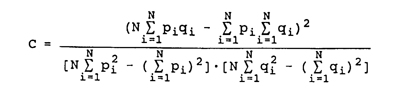
- the agreement between the differences p 1 , p 2 , ...p N for one of the fiber ends and the differences q 1 , q 2 , ..., q N for the other one of the fiber ends is in an advantageous way determined by means of a correlation function C according to where a C high value means a good agreement.
- an interpolation function can be calculated for the determined difference values for a body/fiber end as a function of the angular rotation. From the interpolation function further interpolated different values can be determined for the comparisons to the difference values for the other body/fiber end.
- the determination of the angular offset about the longitudinal axis of the fiber ends between the planes through the optically interfering regions or through the stress zones or the two cores of the ends of two optical PM-fibers or twin-core fibers respectively can be used for splicing the fibers to give good splices. Then the end surfaces of the optical fibers are placed close to or essentially at or abutting each other and opposite to each other with the longitudinal axes of the fibers essentially aligned with each other or at least essentially parallel to each other.
- the ends of the fibers are rotated about their longitudinal axes to take an angular position in relation to each other so that an angular alignment between the interfering regions, in particular between the polarization axes or the planes through the stress zones or the double cores, in each fiber end is obtained.
- the fiber ends are rigidly secured or fixed, attached to each other or clamped, in this position in relation to each other in some suitable way, in particular by fusion welding.
- the rotation of the end of one of the fibers in relation to the end of the other fiber should then be made with an angular amount corresponding to the angular offset determined before the rotation.
- Figs. 1a and 1b the light path is schematically illustrated for the travel of a flat light beam (arriving from the top as seen in Figs. 1a, 1b) through an optical PM-fiber 1 having a conventional core 3 and two stress concentration zones 7, as rotated in two different orientations around its longitudinal axis 6.
- the optical fiber 1 has also a cladding 5 having an essentially exterior circular-cylindrical surface surrounding the core 3 and the stress zones 7.
- the zones 7 are located at two places in relation to the longitudinal axis of the fiber which are located more or less exactly diametrically opposite to each other, as seen in a cross sectional view of the fiber.
- Light which is transferred through a PM-fiber 1 can have two polarization modes perpendicular to each other. These two modes have their magnetic and electric field vectors located in symmetry planes in the fiber 1 and more specifically along either one of two polarization axes 8, 8', of which one, 8, as seen in the cross section through the fiber 1, passes centrally through the stress concentration zones 7 and the other polarization plane 8' extends perpendicularly to the first one. Ideally, these planes 8, 8' also pass through the center line 6 of the fiber 1, i.e. through the center of the core 3.
- Figs. 1a and 1b the intensity of light is illustrated which has passed through the fiber where the intensity curve is taken along a direction perpendicular to both the arriving parallel light beam and perpendicular to the longitudinal axis 6 of the optical PM-fiber. The curve is further determined along a line which extends approximately through the focal line of the lens which is formed by the cladding 5 of the fiber 1.
- Fig. 1a an orientation of an optical fiber 1 is shown for which the stress concentration zones 7 are placed so that they both are aligned with and are symmetrically located in relation to the direction of the arriving light beam.
- Light rays which arrive against the stress concentration zones 7 do not significantly add to the light intensity which can be observed at the other side of the fiber 1, i.e. after the travel of the light beams through the fiber 1. Deflection of the light beams take place at the travel thereof into and out of these regions and at reflections at the surface of the stress zones. Since in this case the light rays can pass unobstructedly through the exterior cladding portions of the optical fiber and further, a cylindrical body as has been mentioned above, has a focusing effect on arriving parallel light rays, which is called the lens effect of the optical fiber, a significant light intensity is obtained at the corresponding focus what in the light intensity curve is shown as a rather high central peak 9.
- the orientation of the optical PM-fiber is instead such that the two stress concentrations zones 7 are essentially located along a diameter of the optical fiber 1 which diameter is perpendicular to the direction of the arriving parallel light beam.
- a large portion of the arriving light rays is inhibited to pass through the optical fiber 1 owing to the interfering effect of the stress concentration zones 7.
- the remaining light rays which pass through the optical fiber 1, as if is this was a cylindrical body, are otherwise focused in the usual way according to the lens effect.
- a light intensity curve as illustrated in Fig. 1c below Fig. 1b then has a central peak 9 which has a significantly lower height in this case compared to the curve in Fig. 1c below Fig. 1a.
- Figs. 2a and 2b in the corresponding way, the light path is schematically illustrated for the travel of a light beam through an optical twin-core fiber 1' having two cores 3', as rotated in two different orientations around its longitudinal central axis 6, in Fig. 2a with the plane 8" through the cores 3 aligned with the direction of the incoming light and in Fig. 2b with the plane 8" perpendicular thereto.
- the effect of the optically interfering regions, that is of the cores 3', on the light passing through the fiber 1' is less pronounced.
- the relation of central light intensities in the two orientations is reversed, so that, as illustrated by the intensity curves in Figs.
- This value h is determined for different angular positions of the optical fiber 1, 1', for instance for each tenth degree.
- the determined heights are plotted in the diagram in Fig. 5 for two individual PM-fibers, in this case for two fiber ends which are to be spliced, a left fiber end and a right fiber end.
- their height profiles as is illustrated in Fig. 5, should have principally the same shape and with a suitable translation of the profile curves, they can be made to coincide or agree in the best way.
- the angular translation value obtained thereby will then be the angular offset between the fiber ends in their start positions.
- the index value k is an integer in the interval -N/4 ⁇ k ⁇ N/4 and it then corresponds also to an angular value.
- the correlation is calculated according to the formula (3) for a number of points which correspond to half the total number N of measurement points and thus corresponding to a rotation of a half full term of the fibers.
- the start index k here runs through the integers from and including -9 to and including 8 and thus corresponds to angular positions in the X vector -90°, -80°, ..., 80°.
- a smooth profile curve for the quantity h for each fiber end can be determined by means of a curve fitting method, e.g. by means of interpolation with cubic fitting ("cubic spline").
- the value of k is determined for which the correlation function C' will have a maximal value and this gives a first rough value of the angular offset. Then the finer determination is performed by means of the interpolation method according to the above.
- the measurement values illustrated in Fig. 5 are related to fiber ends of PM-fibers of the same kind. Different fiber types, however, have different h-profiles and examples thereof are illustrated in the diagrams in Figs. 8a - 11b. Thus the profile for a "York Bowtie" PM-fiber having a diameter of 125 ⁇ m is illustrated in Fig. 8a, the cross-section thereof being illustrated in Fig. 8b. This fiber type has two main stress zones approximately having the shape of circular annular segments. In Fig. 9a the h-profile is illustrated for a "Panda" PM-fiber of diameter 125 ⁇ m having basically the same cross-section as the PM-fibers illustrated in Figs. 1a, 1b, 2a and 2b.
- Figs. 10a and 11a the h-profiles are illustrated for "3M" PM-fibers of diameters 80 and 125 ⁇ m respectively, these fibers having an elliptical region in the cladding as viewed in the cross-section.
- the hereby determined angle ⁇ final will not necessarily be the angular offset between the stress concentration zones, as taken for the centres thereof in relation to the longitudinal axis of the respective fiber, or more generally between the polarization axes.
- the constant additional angle can be determined by an active measurement of the extinction ratio for light passing through a splice or by an observation in a microscope of the end surfaces of the fiber ends. As suggested by the diagrams of Figs. 8a - 11b such an additional value may typically have the value of +90° or -90°.
- the extinction ratio can be determined in a splice between two PM-fibers by rotating the spliced fiber, as has been described above for each fiber end, to different angular positions, determining the light intensity curves for places in the spliced fiber on both sides of the splice, calculating the height profiles and using the correlation function for determining the offset angle in the finished fiber splice. Then the ratio can be calculated from formula (12).
- Figs. 12 - 14 the measured and calculated values, corresponding to the diagrams of Figs. 5 - 7, are shown for two fiber ends of twin-core fibers.
- the method described above for determination of the angular offset about the longitudinal axis between two ends of two identical optical fibers can be performed in common processor controlled splicing devices for optical fibers and it can be used therein to achieve in a simple way a splicing of such fibers having splices in which optical interfering regions in a fiber end are essentially aligned with the corresponding optical interfering regions in another fiber end and in which in the special cases thus the polarization axes or the stress concentration zones in PM-fibers or two cores in twin-core fibers are essentially aligned with and located at and against each other.
- Fig. 3 Some essential details of a commercially available splicing device for optical fibers of standard type are illustrated in Fig. 3.
- Two light sources 13 are arranged so that they issue light beams which hit the optical fiber 1 in directions which are perpendicular to each other.
- the light beams through the fibers pass optical lenses 15 of standard quality, are deflected by means of prisms 17 and are collected to a single parallel light beam by means of a beam splitter 19.
- the single parallel light beam thus accomplished is deflected further in a prism 21 and is mapped or reproduced by means of a lens 23 on the light sensitive elements in a video camera, not shown.
- the lens 23 can be included in this video camera.
- the two light sources are hereby activated alternatingly with each other.
- an electric arc is generated between two electrodes 25 which are located so that the arc hits the end surfaces of the two fibers and melts the ends together.
- FIG. 4 A device for splicing two optical fibers is schematically shown in Fig. 4.
- This device is principally a conventional automatic splicing device for optical fibers supplemented with devices for orienting the fibers angularly and possibly also provided with special routines for analysing the determined intensity curves.
- Fig. 4 is also schematic having some parts of the optical system omitted, so that for instance no lenses and prisms are illustrated and only a single light source 13.
- the two optical fibers which are to be spliced to each other are placed with their ends in special retainers 27, by means of which the fibers can be rotated about their longitudinal axes.
- These retainers 27 are, in addition, arranged on the usual alignment supports 29 for the fiber ends of the splicing device.
- the fiber supports 29 can further be operated in relation to each other in the same perpendicular device directions which are indicated by the two light ray directions from the lamps 13 of Fig. 3, and also in the longitudinal direction of the fibers by means of drive motors 31, which are controlled by logical circuits and software in a processor logic module 33.
- the lamp 33 is activated through its own drive circuits 35 by the processor logic 33.
- the electrodes 25 are driven by corresponding drive circuits 37 controlled by the processor logic 33.
- a video camera 39 makes a picture of the fiber ends and provides the corresponding video signals through a video interface 41 to an image processing and image analysis module 43.
- the result of the image processing and the image analysis in this module 43 is fed to the processor logic module 33 and the result can be shown on a monitor 45. Also the directly obtained picture of the end regions of the fibers as depicted by the video camera 39 can be shown on the monitor 45.
- the rotational angles of the fibers are varied from a start position so that curves are obtained for angular values equally distributed over a full turn, for instance as has been proposed above for each tenth degree.
- the heights h of the light intensity profiles for a considered angular position are determined by analysing the curves automatically, determination of the heights of their central peaks and then calculating the average of several such heights. Corresponding numerical values for each fiber end can then continuously be shown on the monitor 45.
- the position of the fibers can need to be adjusted in order to be still observed and it is performed as earlier by the automatic alignment control in the processor logic module 33 by activation of the control motors 31 for the retainers 29.
- the determined h values for the two fibers can be evaluated for determination of the offset between the angular positions about the longitudinal axis of the fibers for the optically interfering regions of the optical fibers in their start positions and thus how much the fibers are to be rotated in relation to each other in order to align these regions of the fibers with each other.
Landscapes
- Physics & Mathematics (AREA)
- Engineering & Computer Science (AREA)
- Plasma & Fusion (AREA)
- General Physics & Mathematics (AREA)
- Optics & Photonics (AREA)
- Mechanical Coupling Of Light Guides (AREA)
Claims (22)
- Verfahren zum Bestimmen des Winkelversatzes zwischen Winkelpositionen von optischen Asymmetrien oder optisch inhomogenen Bereichen (7, 3'), die sich parallel zu longitudinalen Achsen (6) von zwei zylindrischen Körpern (1, 1') erstrecken, wobei die Körper sich in beliebigen Winkelstartpositionen befinden und das Verfahren die folgenden Schritte umfaßt:gekennzeichnet durch die folgenden Schritte:Bestrahlen der Körper (1, 1') mit einem Lichtstrahl, wobei der Lichtstrahl Licht umfaßt, für das die Körper transparent sind;Drehen jedes Körpers (1, 1') um ein vorgegebenes Winkelintervall aus seiner Startwinkelposition um ihre longitudinale Achse (6) und Vergleichen der Bilder, die durch die Bestrahlung gebildet werden;Bestimmen, während der Drehung für verschiedene Winkelpositionen, der Differenz (h) zwischen erstens der Intensität von Licht, das durch den Körper (1, 1') gelaufen ist und, gesehen in einer Richtung entgegengesetzt zu derjenigen des Lichtstrahls, in seiner Position einem zentralen axialen Abschnitt des Körpers entspricht, und zweitens der Intensität von Licht, das durch den Körper (1, 1') gelaufen ist und, gesehen in der gleichen Richtung entgegengesetzt zu derjenigen des Lichtstrahls, in seiner Position Seitenbereichen entspricht, die sich am nächsten zu dem zentralen axialen Abschnitt des Körpers und außerhalb davon befinden, und eine im wesentlichen konstante Intensität, gesehen über die Seitenbereiche, aufweist, wobei diese im wesentlichen konstante Intensität geringer als die Intensität von Licht ist, das in seiner Position dem zentralen axialen Abschnitt entspricht;Vergleichen der bestimmten Differenzen (h) für einen ersten der Körper mit den bestimmten Differenzen (h) für einen zweiten unterschiedlichen der Körper durch Betrachten der bestimmten Differenzen für den ersten der Körper als Werte einer ersten Funktion der jeweiligen Winkelposition und durch Betrachten der bestimmten Differenzen für den zweiten der Körper als Werte einer zweiten Funktion der jeweiligen Winkelposition, wobei der Vergleichsvorgang durchgeführt wird, indem die erste Funktion durch Hinzufügen von Winkelversätzen einer sich ändernden Größe zu dem Argument davon versetzt wird und die versetzte erste Funktion mit der zweiten Funktion verglichen wird und der Winkelversatz, der die beste Übereinstimmung der versetzten ersten Funktion und der zweiten Funktion ergibt, bestimmt wird und dieser bestimmte Winkelversatz so genommen wird, daß es der Winkelversatz zwischen den Winkelpositionen der optischen Asymmetrien oder optisch inhomogenen Bereichen der zwei zylindrischen Körper ist.
- Verfahren nach Anspruch 1, dadurch gekennzeichnet, daß das vorgegebene Winkelintervall wenigstens eine Hälfte einer vollständigen Umdrehung und vorzugsweise eine vollständige Umdrehung ist.
- Verfahren nach einem der Ansprüche 1 - 2, dadurch gekennzeichnet, daß beim Beleuchten der Körper (1, 1') durch einen Lichtstrahl der Lichtstrahl im wesentlichen senkrecht zu den longitudinalen Richtungen der Körper ist.
- Verfahren nach einem der Ansprüche 1 - 3 für den Fall von zylindrischen Körpern, die nicht identische optische Asymmetrien oder optisch inhomogene Bereiche (7) aufweisen, dadurch gekennzeichnet, daß bevor der bestimmte Winkelversatz genommen wird, um der Winkelversatz zwischen den Winkelpositionen der optischen Asymmetrien oder optisch inhomogenen Bereichen der zwei zylindrischen Körper zu sein, ein konstanter Winkelwert zu dem bestimmten Winkelversatz addiert wird, wobei dieser konstante Winkelwert charakteristisch für das Paar der zwei Körper ist.
- Verfahren nach einem der Ansprüche 1 - 4, dadurch gekennzeichnet, daß die Bestimmung der Differenzen entlang einer Linie durchgeführt wird, die im wesentlichen senkrecht zu der longitudinalen Achse des entsprechenden Körpers (1, 1') ist und einen großen Winkel dazu bildet und nahe zu einer oder im wesentlichen durch eine Fokallinie für den Körper (1, 1'), der als eine optische Linse angesehen wird, verläuft.
- Verfahren nach einem der Ansprüche 1 - 5, dadurch gekennzeichnet, daß beim Bestimmen der Differenz (h) für verschiedene Winkelpositionen für einen Körper, für jede Winkelposition, eine Lichtintensitätskurve entlang einer geraden Linie bestimmt wird, die sich im wesentlichen senkrecht zu der longitudinalen Achse des Körpers erstreckt oder einen großen Winkel dazu bildet, wonach diese Kurve hinsichtlich der Bestimmung der Differenz zwischen dem zentralen Abschnitt (9) der Kurve und den Abschnitten (10) der Kurve, die an den zentralen Abschnitt angrenzen, ausgewertet wird.
- Verfahren nach Anspruch 6, dadurch gekennzeichnet, daß für jede Winkelposition Lichtintensitätskurven für mehrere derartige gerade Linien, die zueinander beabstandet sind, bestimmt werden; und
daß beim Bestimmen der Differenz (h) für eine betrachtete Winkelposition der Durchschnitt der Differenzen verwendet wird, die für die Kurven bestimmt werden, die für diese Winkelposition bestimmt werden. - Verfahren nach einem der Ansprüche 1 - 7, dadurch gekennzeichnet, daß beim Vergleichen der Differenzen p1, p2, ..., pN, die für den ersten der Körper bestimmt werden, und der Differenzen q1, q2, ..., qN, die für den zweiten der Körper bestimmt werden, und beim Bestimmen des Winkelversatzes, der die beste Übereinstimmung ergibt, die beste Übereinstimmung durch Berechnen einer Korrelationsfunktion C gemäßbestimmt wird, wobei ein großer Wert von C eine gute Übereinstimmung bedeutet.

- Verfahren nach einem der Ansprüche 1 - 8, dadurch gekennzeichnet, daß die bestimmten Differenzen (h) für einen Körper (1, 1') als eine Funktion der Winkeldrehung eine Interpolationsfunktion bestimmt wird, aus der weitere interpolierte Differenzwerte für den Vergleich mit den Differenzwerten des anderen Körpers bestimmt werden.
- Einrichtung zum Bestimmen des Versatzes zwischen Winkelpositionen von optischen Asymmetrien oder optischen inhomogenen Bereichen (7, 3'), die sich parallel zu longitudinalen Achsen von zwei zylindrischen Körper (1, 1') erstrecken, wobei die Körper an beliebigen Winkelstartpositionen angeordnet sind und die Einrichtung umfaßt:gekennzeichnet durcheine Einrichtung (13) zum Beleuchten der Körper (1, 1') mit einem Lichtstrahl;eine Einrichtung (47) zum Drehen jedes Körpers (1, 1') um ein vorgegebenes Winkelintervall aus seiner Winkelstartposition um seine longitudinale Achse;eine Einrichtung (39, 41, 43, 33) zum Bestimmen, während der Drehung und für unterschiedliche Winkelpositionen, der Differenz (h) zwischen erstens der Intensität von Licht, das durch den Körper (1, 1') gelaufen ist und, gesehen in einer Richtung entgegengesetzt zu derjenigen des Lichtstrahls, in seiner Position einem zentralen axialen Abschnitt des Körpers entspricht, und zweitens der Intensität von Licht, das durch den Körper (1, 1') gelaufen ist und, gesehen in der Richtung entgegengesetzt zu derjenigen des Lichtstrahls, in seiner Position Seitenbereichen entspricht, die am nächsten zu dem zentralen Achsenabschnitt des Körpers und außerhalb davon angeordnet sind, und eine im wesentlichen konstante Intensität aufweist, wie über die Seitenbereiche gesehen, wobei diese im wesentlichen konstante Intensität kleiner als die Intensität von Licht ist, das in seiner Position dem zentralen Achsenabschnitt entspricht;eine Einrichtung (33) zum Vergleichen der bestimmten Differenzen (h) für einen ersten der Körper mit den bestimmten Differenzen (h) für einen zweiten unterschiedlichen der Körper durch Betrachten der bestimmten Differenzen des ersten der Körper als Werte einer ersten Funktion der jeweiligen Winkelposition und durch Betrachten der bestimmten Differenzen für den zweiten der Körper als Werte einer zweiten Funktion der jeweiligen Winkelposition, wobei der Vergleichsvorgang durchgeführt wird, indem die erste Funktion durch Addieren von Winkelversätzen mit einer sich ändernden Größe zu dem Argument davon versetzt wird und die versetzte erste Funktion mit der zweiten Funktion verglichen wird, und zum Bestimmen des Winkelversatzes, der die beste Übereinstimmung der versetzten ersten Funktion und der zweiten Funktion ergibt; undeine Einrichtung (33) zum Setzen dieses bestimmten Winkelversatzes, um der Winkelversatz zwischen den Winkelpositionen der optischen Asymmetrien oder optisch inhomogenen Bereichen der zwei zylindrischen Körper zu sein.
- Einrichtung nach Anspruch 10, dadurch gekennzeichnet, daß die Bestrahlungseinrichtung (33) angeordnet ist, um einen parallelen Lichtstrahl bereitzustellen und/oder dem Lichtstrahl eine Richtung im wesentlichen senkrecht zu den longitudinalen Richtungen der Körper (1, 1') zu geben.
- Einrichtung nach einem der Ansprüche 10 - 12, dadurch gekennzeichnet, daß die Dreheinrichtung (47) angeordnet ist, um die Körper (1, 1') wenigstens um die Hälfte einer vollen Umdrehung und vorzugsweise um eine volle Umdrehung zu drehen.
- Einrichtung nach einem der Ansprüche 10 - 12, dadurch gekennzeichnet, daß die Einrichtung (39, 41, 43, 33) zum Bestimmen der Differenzen (h) an verschiedenen Winkelpositionen für einen Körper (1, 1') eine Einrichtung umfaßt, um für jede derartige Winkelposition die Lichtintensität entlang einer geraden Linie zu bestimmen, die im wesentlichen senkrecht zu der longitudinalen Achse des Körpers ist und durch einen Fokalbereich oder nahe zu diesen durchgeht, wobei dieser durch die Lichtstrahlen in dem Lichtstrahl gebildet wird, der durch den Hauptabschnitt des Körpers fokussiert worden ist, zu bestimmen.
- Einrichtung nach einem der Ansprüche 10 - 13 für den Fall von zylindrischen Körpern, die nicht identische optische Asymmetrien oder optisch inhomogene Bereiche (7) aufweisen, dadurch gekennzeichnet, daß die Einrichtung (33) zum Setzen des bestimmten Winkelversatzes, um der Winkelversatz zu sein, angeordnet ist, um vor dem Setzen des bestimmten Winkelversatzes, und der Winkelversatz zu sein, zu dem bestimmten Winkelversatz einen konstanten Winkelwert zu addieren, der für das Paar der betrachteten Körper charakteristisch ist.
- Einrichtung nach einem der Ansprüche 10 - 14, dadurch gekennzeichnet, daß die Einrichtung (39, 41, 43, 33) zum Bestimmen der Differenzen (h) an verschiedenen Winkelpositionen für einen Körper (1, 1') umfaßt:eine Einrichtung zum Bestimmen für jede derartige Winkelposition einer Lichtintensitätskurve entlang einer geraden Linie, die im wesentlichen senkrecht zu der longitudinalen Achse des Körpers ist; undeine Einrichtung zum Auswerten von derartigen Kurven zum Bestimmen der Differenz zwischen dem zentralen Abschnitt (9) der Kurve und den Bereichen (10) der Kurve, die sich benachbart zu dem zentralen Abschnitt der Kurve befinden.
- Einrichtung nach Anspruch 15, dadurch gekennzeichnet, daßdie Einrichtung zum Bestimmen für jede Winkelposition einer Lichtintensitätskurve angeordnet ist, um Lichtintensitätskurven entlang mehrere derartiger gerader Linien beabstandet zueinander zu bestimmen; unddie Einrichtung zum Auswerten der Kurven angeordnet ist, um beim Bestimmen der Differenz für eine betrachtete Winkelposition, die Differenz als den Durchschnittswert der Differenzen zu bestimmen, die aus den Kurven bestimmt werden, die für diese Winkelposition bestimmt werden.
- Einrichtung nach einem der Ansprüche 10 - 16, dadurch gekennzeichnet, daß die Einrichtung zum Vergleichen der bestimmten Differenzen und zum Bestimmen der Winkelposition angeordnet ist, um zum Bestimmen des Übereinstimmungsgrades zwischen Differenzen p1, p2, ..., pN für einen der Körper und Differenzen q1, q2, ..., qN für den anderen der Körper, eine Korrelationsfunktion C gemäßzu bestimmen, wobei ein großer Wert C eine gute Übereinstimmung bedeutet.
- Einrichtung nach einem der Ansprüche 10 - 17, gekennzeichnet durch eine Einrichtung, um für die bestimmten Differenzen (h) für einen Körper als eine Funktion der Winkelposition eine Interpolationsfunktion zu bestimmen und daraus ferner interpolierte Differenzwerte zu bestimmen; und
die Einrichtung (39, 41, 43, 33) zum Vergleichen der bestimmten Differenzen zum Bestimmen der Winkelposition auch angeordnet ist, um diese interpolierten Differenzwerte für den Vergleich mit den Differenzwerten für den anderen Körper zu verwenden. - Verwendung des Verfahrens gemäß irgendeinem der Ansprüche 1 - 9 beim Spleißen von zwei optischen Fasern (1, 1'), wobei jede wenigstens eine Asymmetrie oder insbesondere wenigstens einen optisch inhomogenen Bereich (7, 3') umfaßt, der sich in die longitudinalen Richtungen der Fasern (1, 1') erstreckt und in bezug auf eine longitudinale Achse (6) der Fasern exzentrisch angeordnet ist, umfassend die Schritte,dadurch gekennzeichnet, daß die Drehung des Endes einer der Fasern in bezug zu dem Ende der anderen der Fasern um einen Winkelbetrag gemacht wird, der dem Winkelversatz entspricht, der für die zwei Faserenden bestimmt wird, gemäß dem Verfahren in irgendeinem der Ansprüche 1 - 9.daß Endoberflächen der optischen Fasern (1, 1') nahe oder gegenüberliegend zueinander und gegenüberliegend zueinander, wobei die longitudinalen Achsen (6) der Fasern im wesentlichen zueinander ausgerichtet sind oder wenigstens im wesentlichen parallel zueinander angeordnet sind, angeordnet werden;daß die Enden der Fasern (1, 1') um ihre longitudinalen Achsen gedreht werden, um eine Winkelposition zueinander aufzuweisen, so daß eine Ausrichtung zwischen den axialen Asymmetrien oder den optisch inhomogenen Bereichen (7, 3') in jedem Faserende erhalten wird;daß die Faserenden in dieser Position zueinander fixiert und/oder geklemmt werden und insbesondere durch Erwärmen und Zusammenverschmelzen von Bereichen an den Endflächen der Fasern (1, 1') verbunden werden;
- Verwendung nach Anspruch 19, dadurch gekennzeichnet, daß beim Bestimmen des Winkelversatzes die Faserenden, die nahe zueinander angeordnet sind, von der Seite davon gleichzeitig mit dem gleichen Lichtstrahl bestrahlt werden.
- Spleißeinrichtung zum Verspleißen der Enden von zwei optischen Fasern (1, 1'), die jeweils wenigstens eine axiale Asymmetrie oder wenigstens einen optisch inhomogenen Bereich (7, 3') umfassen, der sich in der longitudinalen Richtung der Faser erstreckt und in bezug zu einer longitudinalen Achse (6) der Faser exzentrisch angeordnet ist, wobei die Spleißeinrichtung umfaßt:eine Einrichtung zum Anordnen der Endoberflächen der optischen Faser (1, 1') nahe zueinander oder aneinander und gegenüberliegend zueinander, wobei die longitudinalen Achsen (6) der Fasern im wesentlichen zueinander ausgerichtet oder wenigstens im wesentlichen parallel zueinander sind;eine Einrichtung (25, 37) zum Verbinden der Faserenden miteinander;die Einrichtung gemäß einem der Ansprüche 10 - 18; undeine Einrichtung zum Drehen des Endes einer der Fasern um ihre longitudinale Achse in bezug zu dem Ende der anderen der Fasern um einen Winkelbetrag, der dem Winkelversatz entspricht, der für die Faserenden bestimmt wird, so daß eine Ausrichtung zwischen den axialen Asymmetrien oder den optisch inhomogenen Bereichen in jedem Faserende erhalten wird.
- Einrichtung nach Anspruch 21, dadurch gekennzeichnet, daß die Beleuchtungseinrichtung (13) einen Lichtstrahl umfaßt, der angeordnet ist, um die Faserenden, die nahe zueinander angeordnet sind, gleichzeitig und von den Seiten davon zu beleuchten.
Applications Claiming Priority (7)
| Application Number | Priority Date | Filing Date | Title |
|---|---|---|---|
| SE9303974 | 1993-11-29 | ||
| SE9303974A SE502246C2 (sv) | 1993-11-29 | 1993-11-29 | Förfarande och anordning för bestämning av utsläckningsförhållandet mellan två ändar hos optiska PM-fibrer |
| SE9303973 | 1993-11-29 | ||
| SE9303973A SE502247C2 (sv) | 1993-11-29 | 1993-11-29 | Förfarande och anordning för bestämning av vinkelförskjutningen mellan optiska PM-fibrer samt användning av förfarandet och anordningen |
| SE9400780A SE503451C2 (sv) | 1993-11-29 | 1994-03-08 | Förfarande och anordning för bestämning av förskjutningen mellan vinkellägen kring längdaxlarna hos optiskt inhomogena områden i två cylindriska kroppar samt användning av förfarandet respektive anordningen |
| SE9400780 | 1994-08-25 | ||
| PCT/SE1994/001146 WO1995014945A1 (en) | 1993-11-29 | 1994-11-29 | Determination of angular offset between optical fibers having optical, axial asymmetry and alignment and splicing of such fibers |
Publications (2)
| Publication Number | Publication Date |
|---|---|
| EP0681707A1 EP0681707A1 (de) | 1995-11-15 |
| EP0681707B1 true EP0681707B1 (de) | 1999-10-13 |
Family
ID=27355738
Family Applications (1)
| Application Number | Title | Priority Date | Filing Date |
|---|---|---|---|
| EP95903082A Expired - Lifetime EP0681707B1 (de) | 1993-11-29 | 1994-11-29 | Bestimmung des winkelversutzes zwischen optischen fasern mit optischer, axialer asymmetrie und ausrichtung und spleissen von solchen fasern |
Country Status (5)
| Country | Link |
|---|---|
| US (1) | US5572313A (de) |
| EP (1) | EP0681707B1 (de) |
| JP (1) | JP3737107B2 (de) |
| DE (1) | DE69421166T2 (de) |
| WO (1) | WO1995014945A1 (de) |
Cited By (1)
| Publication number | Priority date | Publication date | Assignee | Title |
|---|---|---|---|---|
| LU506125B1 (en) * | 2024-01-15 | 2025-07-15 | Microsoft Technology Licensing Llc | Azimuthal alignment of antiresonant hollow core fibers |
Families Citing this family (32)
| Publication number | Priority date | Publication date | Assignee | Title |
|---|---|---|---|---|
| US6207922B1 (en) | 1994-03-08 | 2001-03-27 | Telefonaktiebolaget Lm Ericsson (Publ) | Electric control for welding optical fibers |
| SE505771C2 (sv) * | 1994-10-24 | 1997-10-06 | Ericsson Telefon Ab L M | Förfarande och anordning för bestämning av avståndet mellan kärnor i en optisk fiber samt användning av förfarandet respektive anordningen |
| SE503513C2 (sv) * | 1994-11-17 | 1996-07-01 | Ericsson Telefon Ab L M | Förfarande och anordning för bestämning av tjocklek och koncentricitet hos ett skikt pålagt på en cylindrisk kropp |
| SE505782C2 (sv) * | 1995-04-28 | 1997-10-06 | Ericsson Telefon Ab L M | Förfarande för styrning av temperatur under en fiberskarvningsprocess samt förfarande och anordning för att tillverka en optisk fiberdämpningsanordning |
| SE505591C2 (sv) * | 1995-04-28 | 1997-09-22 | Ericsson Telefon Ab L M | Sätt och anordning för tillverkning av en optisk fiberdämpningsanordning samt optisk dämpningsanordning |
| US5729622A (en) * | 1995-08-02 | 1998-03-17 | Lucent Technologies Inc. | Automatic inspection system for contactlessly measuring an offset of a central feature of an object |
| US5768409A (en) * | 1995-08-02 | 1998-06-16 | Lucent Technologies Inc. | Automatic inspection method for contactlessly measuring an offset of a central feature of an object |
| SE515551C2 (sv) * | 1995-09-27 | 2001-08-27 | Ericsson Telefon Ab L M | Förfarande för att skala en kabel samt verktyg för avlägsnande av skyddshölje på kablar |
| SE506956C2 (sv) | 1995-10-24 | 1998-03-09 | Ericsson Telefon Ab L M | Förfarande och anordning för att bestämma vinkelläget för en optisk axiell asymmetri, samt användning av förfarandet respektive anordningen |
| JP3500850B2 (ja) * | 1996-04-23 | 2004-02-23 | 住友電気工業株式会社 | リボン型光ファイバの突き合せ部を観察する方法及び観察装置 |
| SE511817C2 (sv) * | 1996-07-19 | 1999-11-29 | Ericsson Telefon Ab L M | Förfarande och anordning för att bestämma vinkelläget för minst en axiell optisk asymmetri, samt användning av förfarandet respektive anordningen |
| US5995232A (en) * | 1997-07-14 | 1999-11-30 | U.S. Philips Corporation | Method of and device for inspecting a PCB |
| JPH11151229A (ja) * | 1997-11-21 | 1999-06-08 | Kdk Corp | 非接触非侵襲測定方法及び装置 |
| US6011616A (en) * | 1998-10-02 | 2000-01-04 | Lucent Technologies, Inc. | Systems and methods for measuring the concentricity of a core to a ferrule |
| JP2002333384A (ja) | 2001-05-10 | 2002-11-22 | Fujikura Ltd | 定偏波光ファイバの偏波面の角度ずれ推定方法及び定偏波光ファイバの接続方法 |
| JP2002350110A (ja) * | 2001-05-28 | 2002-12-04 | Tokyo Seimitsu Co Ltd | ワークの中心位置検出方法及び装置 |
| SE0200569L (sv) * | 2002-02-26 | 2003-10-23 | Ericsson Telefon Ab L M | Inriktning av PM-fibrer |
| JP4102707B2 (ja) * | 2003-05-19 | 2008-06-18 | 株式会社フジクラ | 定偏波光ファイバ自動判別方法及びその装置並びに定偏波光ファイバ接続方法及びその装置 |
| SE530854C2 (sv) * | 2005-12-30 | 2008-09-30 | Ericsson Telefon Ab L M | Inriktning av optiska fibrer vid dessas skarvning |
| SE530730C2 (sv) * | 2005-12-30 | 2008-08-26 | Ericsson Telefon Ab L M | Inriktning av optiska fibrer vid dessas skarvning |
| CN101375191B (zh) * | 2005-12-30 | 2012-10-10 | 艾利森电话股份有限公司 | 光纤的位置确定 |
| SE529875C2 (sv) * | 2005-12-30 | 2007-12-18 | Ericsson Telefon Ab L M | Placering av optiska fibrer i läge |
| US8998511B2 (en) * | 2008-07-08 | 2015-04-07 | Telefonaktiebolaget L M Ericsson (Publ) | Cladding alignment for fusion splicing optical fibers |
| WO2010039951A1 (en) * | 2008-10-01 | 2010-04-08 | Afl Telecommunications Llc | Method of aligning polarization-maintaining optical fiber by image profile analysis |
| WO2013003335A1 (en) | 2011-06-27 | 2013-01-03 | Vytran, Llc | Apparatus and methods for the determination of a birefringence axis of a polarization-maintaining optical fiber |
| JP2015004695A (ja) * | 2011-10-21 | 2015-01-08 | コニカミノルタ株式会社 | 結合方法 |
| CN104849800A (zh) * | 2015-06-09 | 2015-08-19 | 长飞(武汉)光系统股份有限公司 | 一种熊猫型保偏光纤侧面成像与自动化对准定位的方法 |
| US10310184B2 (en) * | 2017-03-07 | 2019-06-04 | Afl Telecommunications Llc | Methods for splicing optical fibers |
| JP6928854B2 (ja) * | 2019-03-08 | 2021-09-01 | 古河電気工業株式会社 | 融着接続機及び光ファイバの回転調心方法 |
| US11762148B2 (en) | 2020-12-01 | 2023-09-19 | Afl Telecommunications Llc | Control systems and methods for aligning multicore fiber optic cables |
| JP7527436B1 (ja) * | 2023-04-26 | 2024-08-02 | 株式会社フジクラ | 調心方法、調心システム、及び、ファイバ接続体の製造方法 |
| JPWO2024225286A1 (de) * | 2023-04-26 | 2024-10-31 |
Family Cites Families (11)
| Publication number | Priority date | Publication date | Assignee | Title |
|---|---|---|---|---|
| JPS63106706A (ja) * | 1986-10-24 | 1988-05-11 | Fujikura Ltd | 光ファイバの融着接続装置 |
| EP0280562A2 (de) * | 1987-02-26 | 1988-08-31 | BICC Public Limited Company | Spleissen von optischen Fasern |
| DE3724914A1 (de) * | 1987-07-28 | 1989-02-09 | Kabelmetal Electro Gmbh | Verfahren zum verbinden von optischen fasern |
| US5013345A (en) * | 1987-12-04 | 1991-05-07 | Fujikura Ltd. | Method of fusion-splicing polarization maintaining optical fibers |
| JPH026908A (ja) * | 1988-06-24 | 1990-01-11 | Hitachi Cable Ltd | 光ファイバの融着接続法 |
| US5002351A (en) * | 1988-07-05 | 1991-03-26 | Preformed Line Products Company | Fusion splicer for optical fibers |
| US5170456A (en) * | 1988-09-07 | 1992-12-08 | Fujikura Ltd. | Apparatus for aligning a plurality of single-fiber cables |
| US5046813A (en) * | 1988-09-07 | 1991-09-10 | Fujikura Ltd. | Method and apparatus for aligning a plurality of single-fiber cables, and method of simultaneously fusion-splicing such cables |
| DE4025351A1 (de) * | 1990-08-10 | 1992-02-13 | Philips Patentverwaltung | Einrichtung zum verschweissen zweier gruppen von lichtwellenleitern |
| JP2638690B2 (ja) * | 1991-03-22 | 1997-08-06 | 株式会社フジクラ | 光ファイバ融着接続機 |
| US5323225A (en) * | 1992-08-26 | 1994-06-21 | Andrew Corporation | Method of determining azimuthal position of transverse axes of optical fibers with elliptical cores |
-
1994
- 1994-11-29 DE DE69421166T patent/DE69421166T2/de not_active Expired - Lifetime
- 1994-11-29 US US08/350,998 patent/US5572313A/en not_active Expired - Lifetime
- 1994-11-29 EP EP95903082A patent/EP0681707B1/de not_active Expired - Lifetime
- 1994-11-29 WO PCT/SE1994/001146 patent/WO1995014945A1/en not_active Ceased
- 1994-11-29 JP JP51501395A patent/JP3737107B2/ja not_active Expired - Lifetime
Cited By (2)
| Publication number | Priority date | Publication date | Assignee | Title |
|---|---|---|---|---|
| LU506125B1 (en) * | 2024-01-15 | 2025-07-15 | Microsoft Technology Licensing Llc | Azimuthal alignment of antiresonant hollow core fibers |
| WO2025155350A1 (en) * | 2024-01-15 | 2025-07-24 | Microsoft Technology Licensing, Llc | Azimuthal alignment of antiresonant hollow core fibers |
Also Published As
| Publication number | Publication date |
|---|---|
| DE69421166T2 (de) | 2000-03-09 |
| JP3737107B2 (ja) | 2006-01-18 |
| WO1995014945A1 (en) | 1995-06-01 |
| EP0681707A1 (de) | 1995-11-15 |
| JPH08506432A (ja) | 1996-07-09 |
| US5572313A (en) | 1996-11-05 |
| DE69421166D1 (de) | 1999-11-18 |
Similar Documents
| Publication | Publication Date | Title |
|---|---|---|
| EP0681707B1 (de) | Bestimmung des winkelversutzes zwischen optischen fasern mit optischer, axialer asymmetrie und ausrichtung und spleissen von solchen fasern | |
| JP3500850B2 (ja) | リボン型光ファイバの突き合せ部を観察する方法及び観察装置 | |
| US6097869A (en) | Multiple port reflection based circulator | |
| JP3168844B2 (ja) | 定偏波光ファイバの融着接続方法 | |
| CN100412585C (zh) | Pm光纤对准 | |
| EP0774678B1 (de) | Verfahren und Anordnungen bei optischen Fasern | |
| US4474469A (en) | Precise positioning of optical fibers | |
| Hartrumpf et al. | Optical three-dimensional measurements by radially symmetric structured light projection | |
| EP0586964B1 (de) | Verfahren zur azimuthalen Lagebestimmung der Transversalaxen von optischen Fasern mit elliptischen Kernen | |
| JPH0627883B2 (ja) | 複数チャネル光学回転ジョイント | |
| EP0091738B1 (de) | Präzises Einstellen optischer Fasern | |
| JP3654904B2 (ja) | ツインコアを有する光ファイバとシングルコアを有するファイバとの接続 | |
| US5278632A (en) | Multi-axis optical projector | |
| CN114924354B (zh) | 一种多芯光纤的对准方法 | |
| JP4268057B2 (ja) | 偏波面保持光ファイバの偏波面光学主軸決定方法 | |
| JPH02287504A (ja) | 定偏波光フアイバの調心方法 | |
| Katagiri et al. | Optical microscope observation method of a single-mode optical-fiber core for precise core-axis alignment | |
| WO2025142470A1 (ja) | 融着接続機および融着接続方法 | |
| JP2859680B2 (ja) | 偏波保持光ファイバカプラの製造方法 | |
| WO2024225286A1 (ja) | 検査方法及び検査システム | |
| SE503451C2 (sv) | Förfarande och anordning för bestämning av förskjutningen mellan vinkellägen kring längdaxlarna hos optiskt inhomogena områden i två cylindriska kroppar samt användning av förfarandet respektive anordningen | |
| JPH03230105A (ja) | 光ファイバ観察装置 | |
| JPS62198804A (ja) | 光フアイバの軸ずれ測定方法 | |
| SE502247C2 (sv) | Förfarande och anordning för bestämning av vinkelförskjutningen mellan optiska PM-fibrer samt användning av förfarandet och anordningen | |
| Yıldız | Imaging of metal surfaces using confocal laser scanning microscopy |
Legal Events
| Date | Code | Title | Description |
|---|---|---|---|
| PUAI | Public reference made under article 153(3) epc to a published international application that has entered the european phase |
Free format text: ORIGINAL CODE: 0009012 |
|
| 17P | Request for examination filed |
Effective date: 19950627 |
|
| AK | Designated contracting states |
Kind code of ref document: A1 Designated state(s): DE FR GB |
|
| 17Q | First examination report despatched |
Effective date: 19970827 |
|
| GRAG | Despatch of communication of intention to grant |
Free format text: ORIGINAL CODE: EPIDOS AGRA |
|
| GRAG | Despatch of communication of intention to grant |
Free format text: ORIGINAL CODE: EPIDOS AGRA |
|
| GRAH | Despatch of communication of intention to grant a patent |
Free format text: ORIGINAL CODE: EPIDOS IGRA |
|
| GRAH | Despatch of communication of intention to grant a patent |
Free format text: ORIGINAL CODE: EPIDOS IGRA |
|
| GRAA | (expected) grant |
Free format text: ORIGINAL CODE: 0009210 |
|
| AK | Designated contracting states |
Kind code of ref document: B1 Designated state(s): DE FR GB |
|
| REF | Corresponds to: |
Ref document number: 69421166 Country of ref document: DE Date of ref document: 19991118 |
|
| ET | Fr: translation filed | ||
| PLBE | No opposition filed within time limit |
Free format text: ORIGINAL CODE: 0009261 |
|
| STAA | Information on the status of an ep patent application or granted ep patent |
Free format text: STATUS: NO OPPOSITION FILED WITHIN TIME LIMIT |
|
| 26N | No opposition filed | ||
| REG | Reference to a national code |
Ref country code: GB Ref legal event code: IF02 |
|
| PGFP | Annual fee paid to national office [announced via postgrant information from national office to epo] |
Ref country code: FR Payment date: 20131118 Year of fee payment: 20 Ref country code: GB Payment date: 20131127 Year of fee payment: 20 Ref country code: DE Payment date: 20131127 Year of fee payment: 20 |
|
| REG | Reference to a national code |
Ref country code: DE Ref legal event code: R071 Ref document number: 69421166 Country of ref document: DE |
|
| REG | Reference to a national code |
Ref country code: GB Ref legal event code: PE20 Expiry date: 20141128 |
|
| PG25 | Lapsed in a contracting state [announced via postgrant information from national office to epo] |
Ref country code: GB Free format text: LAPSE BECAUSE OF EXPIRATION OF PROTECTION Effective date: 20141128 |