EP0683580A1 - Method for connecting an HDSL transmission link to an SDH network - Google Patents
Method for connecting an HDSL transmission link to an SDH network Download PDFInfo
- Publication number
- EP0683580A1 EP0683580A1 EP95303476A EP95303476A EP0683580A1 EP 0683580 A1 EP0683580 A1 EP 0683580A1 EP 95303476 A EP95303476 A EP 95303476A EP 95303476 A EP95303476 A EP 95303476A EP 0683580 A1 EP0683580 A1 EP 0683580A1
- Authority
- EP
- European Patent Office
- Prior art keywords
- hdsl
- link
- sdh network
- frame
- sdh
- Prior art date
- Legal status (The legal status is an assumption and is not a legal conclusion. Google has not performed a legal analysis and makes no representation as to the accuracy of the status listed.)
- Granted
Links
- 238000000034 method Methods 0.000 title claims abstract description 17
- 230000005540 biological transmission Effects 0.000 title abstract description 15
- 230000001360 synchronised effect Effects 0.000 description 7
- 238000013507 mapping Methods 0.000 description 5
- 230000002457 bidirectional effect Effects 0.000 description 3
- RYGMFSIKBFXOCR-UHFFFAOYSA-N Copper Chemical compound [Cu] RYGMFSIKBFXOCR-UHFFFAOYSA-N 0.000 description 1
- 229910052802 copper Inorganic materials 0.000 description 1
- 239000010949 copper Substances 0.000 description 1
- 230000001419 dependent effect Effects 0.000 description 1
Images


Classifications
-
- H—ELECTRICITY
- H04—ELECTRIC COMMUNICATION TECHNIQUE
- H04J—MULTIPLEX COMMUNICATION
- H04J3/00—Time-division multiplex systems
- H04J3/16—Time-division multiplex systems in which the time allocation to individual channels within a transmission cycle is variable, e.g. to accommodate varying complexity of signals, to vary number of channels transmitted
- H04J3/1605—Fixed allocated frame structures
- H04J3/1611—Synchronous digital hierarchy [SDH] or SONET
Definitions
- the invention relates to a method according to the preamble of the accompanying claim 1 for connecting an HDSL transmission link to an SDH network.
- the HDSL (High bit rate Digital Subscriber Line) transmission technique relates to transmitting a 2 Mbit/s digital signal in a metallic twin cable.
- the ETSI (European Telecommunications and Standards Institute) recommendation DTR/TM-3017 defines the HDSL transmission technique as a transmission method of several different applications.
- An individual HDSL transceiver system comprises transceivers, employing echo cancellation technique, connected to each other via a bidirectional transmission link formed by a (copper) twin cable.
- the HDSL transmission system may comprise two or three such separate transceiver systems adjacent to each other, the transmission rate used over each parallel link being thus a sub-rate of 2 Mbit/s; in the case of three parallel pairs the rate is 784 kbit/s, and in the case of two parallel pairs 1168 kbit/s.
- the aforementioned recommendation defines how 2 Mbit/s signals, such as the VC-12 signals of the SDH network or the 2048 kbit/s signals according to the CCITT recommendations G.703/G.704, are transmitted in the HDSL system.
- the HDSL system is not described closer here, however, since the present invention does not require any changes to be made in the HDSL system, but the system operates in a manner known per se.
- the aforementioned specification is referred to for a more detailed description of the HDSL system.
- the present invention does not require any changes to be made in the SDH (Synchronous Digital Hierarchy) system either, but all the SDH-specific functions needed in the invention are known per se. Therefore the SDH system will not be described closer either.
- SDH Serial Digital Hierarchy
- the SDH system is described in greater detail for example in references [1] and [2] (the references are listed at the end of the specification).
- the ETSI recommendations it is thus possible, through HDSL links, to transmit a VC-12 signal of the SDH network further from the SDH trunk network. In a way this means that the operations of the SDH network are brought closer to the customer (i.e. subscriber).
- the basis for the ETSI recommendations has been that the HDSL link is synchronized with the VC-12 frame, which means in practice that the position of the first byte in the VC-12 frame is fixedly occupied by the V5 byte of the VC-12 frame.
- the VC-12 frame is thus mapped into the 500 ⁇ s core frame of the HDSL system in such a way that the first byte in the VC-12 frame is always the V5 byte, which is mapped into the first byte of the core frame.
- the other bytes of the VC-12 frame are mapped into their own fixed positions.
- the VC-12 signals to be transmitted to the HDSL link may arrive from far away, however, even from another SDH network.
- the generation point of the VC-12 signal is not necessarily situated in the SDH network to which the particular HDSL modem is linked, but it may be located in another SDH network from where it has been transmitted to the network to which the HDSL link is connected.
- the generation point may be situated, for example, in an SDH network located within another country, and thus the VC-12 signal to be transmitted is not necessarily synchronized with the network to which the HDSL link is connected. This is due to the slight difference in rate between the SDH networks, which in turn results from the networks using different timing sources.
- FIG. 1 A case similar to the one described above is shown in the accompanying Figure 1 representing two separate SDH networks 11 and 12, which are synchronized from different timing sources.
- the VC-12 signal is formed in this exemplary case in point P of the network 12, from where it is transmitted to point P1 on the edge of the network 11, the HDSL link 13 being connected to the latter point.
- the interpretation of the TU-12 pointer is performed in point P1 (due to the bidirectional link, the corresponding function is described in the figure with the term "termination”, which means both pointer interpretation and generation, the latter occurring in an opposite direction of transmission).
- the VC-12 signal found as a result of the pointer interpretation is mapped into the frame structure of the HDSL system, where the VC-12 data is transmitted to the subscriber end of the HDSL link, where VC-12 termination (i.e. in this transmission direction the disassembly of the VC-12 frame) is performed.
- the frame synchronization signals transmitted over the interface between the SDH network and the HDSL system are denoted in Figure 1 with reference symbol VC-12_SYNC.
- control information when other kind of information, e.g. control information, is transmitted to an HDSL link, the information is synchronized with the timing source of the network where it is formed.
- this control information does not pass through the networks in the same way as the VC-12 frames, since there are no similar justification procedures, based on pointers, for the control information as there are for the actual data. Therefore there are sometimes errors in the control information transmitted to the HDSL link, since the incoming signal and the HDSL link are not quite synchronized.
- the access network to which the HDSL link also belongs, has its own operator.
- Access network refers to the part reserved for the end-user of the telecommunications network, in which part the rates of the signals to be transmitted are lower than the rate of the STM-1 signal of the SDH network.
- a subrack 31 of a node equipment situated on the edge (e.g. point P1 in Figure 1) of the SDH network typically comprises a bus 32, where TU-level signals are transmitted.
- TU-12 signals from the SDH network are passed to a TU-12 termination unit 34, where the interpretation of the TU-12 pointer, and in the other transmission direction also the generation of the pointer, are performed (due to the bidirectional link, the termination refers in this connection both to the interpretation and generation).
- the phase of the VC-12 signal is found, and the VC-12 frames can be mapped in the HDSL device 35 into the core frame which is transmitted further within the HDSL frame via twin cables 36 to a device 37 located on the subscriber side of the link.
- An HDSL device 38 of the subscriber side comprises a VC-12 termination unit, where the VC-12 frame is disassembled (and the VC-12 frames transmitted to the SDH network are assembled).
- the subrack In order to distribute from the subrack also a normal 2,048 Mbit/s signal according to the G.703/704 specifications, the subrack also typically comprises a termination unit where the termination of both TU-12 and VC-12 signals is performed (the interpretation and generation of TU-12 pointers and the disassembly and assembly of VC-12 signals).
- This termination unit is denoted by reference numeral 33.
- the problem referred to above results from the pointer interpretation of the TU-12 signal transmitted to the subscriber being performed in the unit 34. If, as a result of the interpretation, the state machine of the unit 34 enters the LOP state (Loss of Pointer) or the AIS state (Alarm Indication Signal), data indicating the state must be placed in the frame transmitted back (in addition to the normal state NORM, the aforementioned states are the main states of the state machine of the pointer, according to the SDH specifications).
- LOP state Loss of Pointer
- AIS state Alarm Indication Signal
- a FERF bit (Far End Receive Failure) in the VC-12 frame must be set, in the overhead byte of the frame to be transmitted back (the eighth bit in a V5 byte), to a value corresponding to the state in question.
- the corresponding data must be transmitted over the HDSL link from the unit 34 performing the interpretation to the unit (unit 39) on the subscriber end, forming the frame to be transmitted back (this operation is denoted in the figure by reference symbol FERF).
- the greatest problem in this case is due to the time demands, set in the SDH recommendations, according to which this data must be transmitted back within two multiframes (corresponds to 4 milliseconds). Complying with such a time demand is difficult and requires more complex equipment than previously.
- the purpose of the present invention is to eliminate the above-described problems by providing a new type of method of connecting the SDH network and the HDSL link.
- This aim is achieved with the method according to the invention, which is characterized in that a TU-12 level signal is transmitted over the HDSL link by performing the interpretation and generation of the TU-12 pointers in the subscriber end of the HDSL link.
- the idea of the invention is thus to transmit a TU-12 signal as such over the HDSL link and to perform the interpretation of the TU-12 pointers only beyond the HDSL link.
- the idea is thus in a way to transfer some properties (justification procedure) of the SDH network to the part of the telecommunications network situated beyond the HDSL link.
- the aforementioned time demand causes no problems since the interpretation of the TU-12 pointer and the generation of the VC-12 frame transmitted back are performed at the same point.
- the arrangement according to the invention shown in Figure 3 corresponds otherwise to the known arrangement shown in Figure 2, but in the equipment of the invention the termination of the TU-12 frame is not performed in the SDH subrack, but the termination has been transferred to the termination unit 42 of the HDSL device situated at the subscriber end, the termination of both TU-12 and VC-12 frames occurring in this unit (the interpretation and generation of the TU pointers and the disassembly and assembly of VC-12 frames). Furthermore, in the arrangement according to the invention there is between the data bus 32 of the SDH subrack and the HDSL equipment only the processing unit 41 of the pointer, in which unit new state data is calculated for the pointers of the TU-12 signals to be transmitted to the SDH network.
- the TU-12 signals are transmitted as such to the HDSL link.
- new values have to be calculated for the TU pointers in the SDH subrack, since the TU-12 frames must be transmitted on the bus in a particular phase (required by the bus), and the TU-12 frames from the subscriber cannot be aligned with the frame alignment required by the bus, for the reason alone that the length (delay) of the subscriber lines varies.
- the frame synchronization signals (indicating the location of the V1 byte of the TU-12 frame) are denoted in Figure 3 by reference symbol TU-12_SYNC.
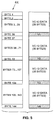
- the TU-12 frame may be mapped into the core frame of the HDSL link for example in the manner shown in the accompanying Figure 4.
- the left side of the figure shows one HDSL core frame 44 having the length of 500 ⁇ s and 144 bytes.
- the V1 byte is mapped, according to the invention, into the first byte of the core frame after which the other pointer bytes (V2...V4) are located at even intervals in the frame, i.e. in positions 37, 73 and 109.
- the advantage of this mapping alternative is that the TU-12 frame may be transmitted as such to the HDSL system.
- the pointer state is interpreted in a manner known per se.
- the pointer value obtained on the basis of the interpretation indicates then the location of the first byte of the VC-12 frame, i.e. the location of the V5 byte in the TU-12 frame.
- FIG. 5 shows another mapping alternative.
- the V1 byte is mapped into byte 36 of the core frame, after which the other V bytes (V2...V4) are again located at even intervals in the frame, i.e. in bytes 72, 108 and 144.
- these bytes are fixed stuffing.
Landscapes
- Engineering & Computer Science (AREA)
- Computer Networks & Wireless Communication (AREA)
- Signal Processing (AREA)
- Communication Control (AREA)
- Time-Division Multiplex Systems (AREA)
- Data Exchanges In Wide-Area Networks (AREA)
Abstract
Description
- The invention relates to a method according to the preamble of the accompanying
claim 1 for connecting an HDSL transmission link to an SDH network. - The HDSL (High bit rate Digital Subscriber Line) transmission technique relates to transmitting a 2 Mbit/s digital signal in a metallic twin cable. The ETSI (European Telecommunications and Standards Institute) recommendation DTR/TM-3017 defines the HDSL transmission technique as a transmission method of several different applications. An individual HDSL transceiver system comprises transceivers, employing echo cancellation technique, connected to each other via a bidirectional transmission link formed by a (copper) twin cable. The HDSL transmission system may comprise two or three such separate transceiver systems adjacent to each other, the transmission rate used over each parallel link being thus a sub-rate of 2 Mbit/s; in the case of three parallel pairs the rate is 784 kbit/s, and in the case of two parallel pairs 1168 kbit/s. The aforementioned recommendation defines how 2 Mbit/s signals, such as the VC-12 signals of the SDH network or the 2048 kbit/s signals according to the CCITT recommendations G.703/G.704, are transmitted in the HDSL system. The HDSL system is not described closer here, however, since the present invention does not require any changes to be made in the HDSL system, but the system operates in a manner known per se. The aforementioned specification is referred to for a more detailed description of the HDSL system.
- The present invention does not require any changes to be made in the SDH (Synchronous Digital Hierarchy) system either, but all the SDH-specific functions needed in the invention are known per se. Therefore the SDH system will not be described closer either. The SDH system is described in greater detail for example in references [1] and [2] (the references are listed at the end of the specification).
- According to the ETSI recommendations, it is thus possible, through HDSL links, to transmit a VC-12 signal of the SDH network further from the SDH trunk network. In a way this means that the operations of the SDH network are brought closer to the customer (i.e. subscriber). The basis for the ETSI recommendations has been that the HDSL link is synchronized with the VC-12 frame, which means in practice that the position of the first byte in the VC-12 frame is fixedly occupied by the V5 byte of the VC-12 frame. According to the ETSI recommendations, the VC-12 frame is thus mapped into the 500 µs core frame of the HDSL system in such a way that the first byte in the VC-12 frame is always the V5 byte, which is mapped into the first byte of the core frame. Correspondingly, the other bytes of the VC-12 frame are mapped into their own fixed positions.
- The VC-12 signals to be transmitted to the HDSL link may arrive from far away, however, even from another SDH network. The generation point of the VC-12 signal is not necessarily situated in the SDH network to which the particular HDSL modem is linked, but it may be located in another SDH network from where it has been transmitted to the network to which the HDSL link is connected. The generation point may be situated, for example, in an SDH network located within another country, and thus the VC-12 signal to be transmitted is not necessarily synchronized with the network to which the HDSL link is connected. This is due to the slight difference in rate between the SDH networks, which in turn results from the networks using different timing sources.
- A case similar to the one described above is shown in the accompanying Figure 1 representing two
separate SDH networks network 12, from where it is transmitted to point P1 on the edge of thenetwork 11, theHDSL link 13 being connected to the latter point. The interpretation of the TU-12 pointer is performed in point P1 (due to the bidirectional link, the corresponding function is described in the figure with the term "termination", which means both pointer interpretation and generation, the latter occurring in an opposite direction of transmission). The VC-12 signal found as a result of the pointer interpretation is mapped into the frame structure of the HDSL system, where the VC-12 data is transmitted to the subscriber end of the HDSL link, where VC-12 termination (i.e. in this transmission direction the disassembly of the VC-12 frame) is performed. The frame synchronization signals transmitted over the interface between the SDH network and the HDSL system are denoted in Figure 1 with reference symbol VC-12_SYNC. - In a case like Figure 1, when other kind of information, e.g. control information, is transmitted to an HDSL link, the information is synchronized with the timing source of the network where it is formed. However, this control information does not pass through the networks in the same way as the VC-12 frames, since there are no similar justification procedures, based on pointers, for the control information as there are for the actual data. Therefore there are sometimes errors in the control information transmitted to the HDSL link, since the incoming signal and the HDSL link are not quite synchronized.
- In many cases the access network, to which the HDSL link also belongs, has its own operator. (Access network refers to the part reserved for the end-user of the telecommunications network, in which part the rates of the signals to be transmitted are lower than the rate of the STM-1 signal of the SDH network.) Thus, the basic idea of the ETSI recommendations could in the above-described cases lead to the reliability of the HDSL link being dependent on the quality of the signal transmitted by another operator (the operator of the network where the signal is formed), for example the quality of the synchronization. Such a situation is naturally not desirable for the operator responsible for the HDSL link.
- The basic idea of the ETSI recommendations also leads to another problem which is illustrated in Figure 2, which shows in greater detail the interface of the SDH network and the HDSL link, operating in the manner suggested by ETSI. A
subrack 31 of a node equipment situated on the edge (e.g. point P1 in Figure 1) of the SDH network typically comprises abus 32, where TU-level signals are transmitted. TU-12 signals from the SDH network are passed to a TU-12termination unit 34, where the interpretation of the TU-12 pointer, and in the other transmission direction also the generation of the pointer, are performed (due to the bidirectional link, the termination refers in this connection both to the interpretation and generation). As a result of the pointer interpretation, the phase of the VC-12 signal is found, and the VC-12 frames can be mapped in theHDSL device 35 into the core frame which is transmitted further within the HDSL frame viatwin cables 36 to adevice 37 located on the subscriber side of the link. AnHDSL device 38 of the subscriber side comprises a VC-12 termination unit, where the VC-12 frame is disassembled (and the VC-12 frames transmitted to the SDH network are assembled). - The other components (cross-connect devices or the like), which are connected to the
bus 32 of the subrack and through which the TU-12 signal is transmitted further to the SDH network, are not described in greater detail, since they are not included within the scope of the present invention. The more detailed structure of these other components may also be modified within the prior art. - In order to distribute from the subrack also a normal 2,048 Mbit/s signal according to the G.703/704 specifications, the subrack also typically comprises a termination unit where the termination of both TU-12 and VC-12 signals is performed (the interpretation and generation of TU-12 pointers and the disassembly and assembly of VC-12 signals). This termination unit is denoted by
reference numeral 33. - The problem referred to above results from the pointer interpretation of the TU-12 signal transmitted to the subscriber being performed in the
unit 34. If, as a result of the interpretation, the state machine of theunit 34 enters the LOP state (Loss of Pointer) or the AIS state (Alarm Indication Signal), data indicating the state must be placed in the frame transmitted back (in addition to the normal state NORM, the aforementioned states are the main states of the state machine of the pointer, according to the SDH specifications). This means that in the VC-12termination unit 39 of the subscriber end, a FERF bit (Far End Receive Failure) in the VC-12 frame must be set, in the overhead byte of the frame to be transmitted back (the eighth bit in a V5 byte), to a value corresponding to the state in question. The corresponding data must be transmitted over the HDSL link from theunit 34 performing the interpretation to the unit (unit 39) on the subscriber end, forming the frame to be transmitted back (this operation is denoted in the figure by reference symbol FERF). The greatest problem in this case is due to the time demands, set in the SDH recommendations, according to which this data must be transmitted back within two multiframes (corresponds to 4 milliseconds). Complying with such a time demand is difficult and requires more complex equipment than previously. - The purpose of the present invention is to eliminate the above-described problems by providing a new type of method of connecting the SDH network and the HDSL link. This aim is achieved with the method according to the invention, which is characterized in that a TU-12 level signal is transmitted over the HDSL link by performing the interpretation and generation of the TU-12 pointers in the subscriber end of the HDSL link.
- The idea of the invention is thus to transmit a TU-12 signal as such over the HDSL link and to perform the interpretation of the TU-12 pointers only beyond the HDSL link. The idea is thus in a way to transfer some properties (justification procedure) of the SDH network to the part of the telecommunications network situated beyond the HDSL link.
- When the arrangement according to the present invention is used, the aforementioned time demand causes no problems since the interpretation of the TU-12 pointer and the generation of the VC-12 frame transmitted back are performed at the same point.
- In the following, the invention and its preferred embodiments will be described in greater detail with reference to Figures 3 to 5 in the examples according to the accompanying drawings, in which
- Figure 1 shows two separate SDH networks, to one of which an HDSL link is connected.
- Figure 2 illustrates the manner in which an HDSL link is connected to an SDH network according to the principle of the ETSI recommendations,
- Figure 3 illustrates the manner in which an HDSL link is connected to an SDH network according to the principle of the present invention,
- Figure 4 shows a first preferred manner of mapping a TU-12 frame into a core frame of an HDSL link, and
- Figure 5 shows a second preferred manner of mapping a TU-12 frame into a core frame of an HDSL link.
- The arrangement according to the invention shown in Figure 3 corresponds otherwise to the known arrangement shown in Figure 2, but in the equipment of the invention the termination of the TU-12 frame is not performed in the SDH subrack, but the termination has been transferred to the
termination unit 42 of the HDSL device situated at the subscriber end, the termination of both TU-12 and VC-12 frames occurring in this unit (the interpretation and generation of the TU pointers and the disassembly and assembly of VC-12 frames). Furthermore, in the arrangement according to the invention there is between thedata bus 32 of the SDH subrack and the HDSL equipment only theprocessing unit 41 of the pointer, in which unit new state data is calculated for the pointers of the TU-12 signals to be transmitted to the SDH network. In the opposite direction of transmission (from the SDH network to the subscriber), no processing is performed in the processing unit, but the TU-12 signals are transmitted as such to the HDSL link. In the transmission from the subscriber to the SDH network, new values have to be calculated for the TU pointers in the SDH subrack, since the TU-12 frames must be transmitted on the bus in a particular phase (required by the bus), and the TU-12 frames from the subscriber cannot be aligned with the frame alignment required by the bus, for the reason alone that the length (delay) of the subscriber lines varies. The frame synchronization signals (indicating the location of the V1 byte of the TU-12 frame) are denoted in Figure 3 by reference symbol TU-12_SYNC. - The TU-12 frame may be mapped into the core frame of the HDSL link for example in the manner shown in the accompanying Figure 4. The left side of the figure shows one
HDSL core frame 44 having the length of 500 µs and 144 bytes. The V1 byte is mapped, according to the invention, into the first byte of the core frame after which the other pointer bytes (V2...V4) are located at even intervals in the frame, i.e. inpositions - Figure 5 shows another mapping alternative. In this case, the V1 byte is mapped into
byte 36 of the core frame, after which the other V bytes (V2...V4) are again located at even intervals in the frame, i.e. inbytes - Even though on the basis of Figures 2 and 3 it might seem that the equipment at the subscriber end would be more complex than previously when the method according to the invention is used, this is not the case since the operations performed by
units - Even though the invention is described above with reference to the examples according to the accompanying drawings, it is clear that the invention is not restricted thereto, but it can be modified in many ways within the inventive idea disclosed above and in the appended claims. Thus, for example the more detailed structure of the equipment may be modified in many ways without deviating from the principle according to the invention.
-
- [1]. CCITT Blue Book, Recommendation G.709: "Synchronous Multiplexing Structure", May 1990.
- [2]. SDH - Ny digital hierarki,
TELE 2/90.
Claims (3)
- A method for connecting an HDSL link (36) to an SDH network (11), according to which method- data from the SDH network (11) to the HDSL link (13) is mapped into the frame structure according to the HDSL system, and- pointers required by the SDH network are generated in the frames passing from the HDSL link (13) to the SDH network (11), the pointers indicating the phase of the payload within the frame structure, characterized in that a TU-12 level signal is transmitted over the HDSL link by performing the interpretation and generation of the TU-12 pointers in the subscriber end (37) of the HDSL link.
- A method according to claim 1, characterized in that the TU-12 signal is mapped into the core frame of the HDSL system by transmitting the V1 byte of the TU-12 frame in the first byte of the core frame.
- A method according to claim 1, characterized in that the TU-12 signal is mapped into the core frame of the HDSL system by transmitting the V1 byte of the TU-12 frame in byte 37 of the core frame.
Applications Claiming Priority (2)
| Application Number | Priority Date | Filing Date | Title |
|---|---|---|---|
| FI942372 | 1994-05-20 | ||
| FI942372A FI96080C (en) | 1994-05-20 | 1994-05-20 | Method for connecting an HDSL transmission connection to an SDH network |
Publications (2)
| Publication Number | Publication Date |
|---|---|
| EP0683580A1 true EP0683580A1 (en) | 1995-11-22 |
| EP0683580B1 EP0683580B1 (en) | 2000-09-27 |
Family
ID=8540747
Family Applications (1)
| Application Number | Title | Priority Date | Filing Date |
|---|---|---|---|
| EP95303476A Expired - Lifetime EP0683580B1 (en) | 1994-05-20 | 1995-05-22 | Method for connecting an HDSL transmission link to an SDH network |
Country Status (6)
| Country | Link |
|---|---|
| EP (1) | EP0683580B1 (en) |
| DE (1) | DE69518944T2 (en) |
| DK (1) | DK0683580T3 (en) |
| FI (1) | FI96080C (en) |
| NZ (1) | NZ272163A (en) |
| PT (1) | PT683580E (en) |
Cited By (1)
| Publication number | Priority date | Publication date | Assignee | Title |
|---|---|---|---|---|
| WO1999059276A3 (en) * | 1998-05-13 | 2000-01-27 | Ericsson Telefon Ab L M | Method and arrangement related to synchronous switching |
Citations (1)
| Publication number | Priority date | Publication date | Assignee | Title |
|---|---|---|---|---|
| EP0565890A2 (en) * | 1992-04-16 | 1993-10-20 | Siemens Aktiengesellschaft | Method and system for the transmission of a data signal in a VC-12-container in transmission channels |
-
1994
- 1994-05-20 FI FI942372A patent/FI96080C/en not_active IP Right Cessation
-
1995
- 1995-05-19 NZ NZ272163A patent/NZ272163A/en not_active IP Right Cessation
- 1995-05-22 DK DK95303476T patent/DK0683580T3/en active
- 1995-05-22 PT PT95303476T patent/PT683580E/en unknown
- 1995-05-22 EP EP95303476A patent/EP0683580B1/en not_active Expired - Lifetime
- 1995-05-22 DE DE69518944T patent/DE69518944T2/en not_active Expired - Lifetime
Patent Citations (1)
| Publication number | Priority date | Publication date | Assignee | Title |
|---|---|---|---|---|
| EP0565890A2 (en) * | 1992-04-16 | 1993-10-20 | Siemens Aktiengesellschaft | Method and system for the transmission of a data signal in a VC-12-container in transmission channels |
Non-Patent Citations (2)
| Title |
|---|
| "International Telegraph and Telephone Consultative Committee Blue Book, Recommandation G.709", 1990, article "Synchronous Multiplexing Structure" |
| "SDH - Ny digital hierarki" |
Cited By (1)
| Publication number | Priority date | Publication date | Assignee | Title |
|---|---|---|---|---|
| WO1999059276A3 (en) * | 1998-05-13 | 2000-01-27 | Ericsson Telefon Ab L M | Method and arrangement related to synchronous switching |
Also Published As
| Publication number | Publication date |
|---|---|
| PT683580E (en) | 2001-01-31 |
| FI96080C (en) | 1996-04-25 |
| AU2020295A (en) | 1995-11-30 |
| NZ272163A (en) | 1997-02-24 |
| DE69518944D1 (en) | 2000-11-02 |
| EP0683580B1 (en) | 2000-09-27 |
| HK1011800A1 (en) | 1999-07-16 |
| AU683735B2 (en) | 1997-11-20 |
| DE69518944T2 (en) | 2001-03-01 |
| FI942372A0 (en) | 1994-05-20 |
| FI96080B (en) | 1996-01-15 |
| FI942372L (en) | 1995-11-21 |
| DK0683580T3 (en) | 2000-10-16 |
Similar Documents
| Publication | Publication Date | Title |
|---|---|---|
| US5315594A (en) | Inter-network transport element of sonet overhead | |
| US6009075A (en) | Transport interface for performing protection switching of telecommunications traffic | |
| US5355362A (en) | Digital loop carrier system | |
| DE69637295T2 (en) | DEVICE FOR ADAPTING SMALL-BAND LANGUAGE TRANSPORT OF A LOCAL ACCESS NETWORK FOR TRANSMISSION OVER A BROADBAND NETWORK WITH ASYNCHRONOUS TRANSFER MODE | |
| KR19980701974A (en) | Point-to-multipoint broadband service drop with multiple time slot return channels for consumer premise | |
| US20020141332A1 (en) | Failover apparatus and method for an asynchronous data communication network | |
| US4799217A (en) | Three time slot digital subscriber line termination | |
| US5570344A (en) | Synchronous digital hierarchy transmission device and method for exchanging synchronous digital hierarchy transmission device units | |
| EP0683580B1 (en) | Method for connecting an HDSL transmission link to an SDH network | |
| EP0683579B1 (en) | Method for transmitting control information over an HDSL transmission link | |
| DE60025316T2 (en) | Detecting errors in the previous section for a transparent subsystem | |
| WO1999017483A1 (en) | System and circuit for telecommunications data conversion | |
| US5579300A (en) | Private automatic branch exchange for integrated services digital network | |
| HK1011800B (en) | Method for connecting an hdsl transmission link to an sdh network | |
| HK1011799A (en) | Method for transmitting control information over an hdsl transmission link | |
| EP0648394B1 (en) | Method for receiving a signal used in a synchronous digital telecommunication system | |
| EP1229677A2 (en) | Failover apparatus and method for an asynchronous data communication network | |
| KR100314354B1 (en) | A Basic Rate Interface Unit of Integrated Services Digital Network in Fiber Loop Carrier-Curb Systems | |
| FI97188B (en) | Method of organizing the data communication between two transmission devices at a repeater station in a digital data transmission network and a repeater station applying the method | |
| KR0171763B1 (en) | Other Short Circuit Path Configuration Method Using F1 Byte in Synchronous Transmission Device | |
| Hajbandeh | T1, T3, and SONET Networks | |
| KR19990061492A (en) | Branch / coupling apparatus in optical subscriber transmitter | |
| JP2000324576A (en) | Cross connect device | |
| SE517065C2 (en) | Method and apparatus for organizing data communication between transmission equipment at a branching regenerator point |
Legal Events
| Date | Code | Title | Description |
|---|---|---|---|
| PUAI | Public reference made under article 153(3) epc to a published international application that has entered the european phase |
Free format text: ORIGINAL CODE: 0009012 |
|
| AK | Designated contracting states |
Kind code of ref document: A1 Designated state(s): BE CH DE DK FR GB IT LI NL PT SE |
|
| 17P | Request for examination filed |
Effective date: 19960410 |
|
| RAP1 | Party data changed (applicant data changed or rights of an application transferred) |
Owner name: NOKIA TELECOMMUNICATIONS OY |
|
| GRAG | Despatch of communication of intention to grant |
Free format text: ORIGINAL CODE: EPIDOS AGRA |
|
| 17Q | First examination report despatched |
Effective date: 19990527 |
|
| GRAG | Despatch of communication of intention to grant |
Free format text: ORIGINAL CODE: EPIDOS AGRA |
|
| GRAH | Despatch of communication of intention to grant a patent |
Free format text: ORIGINAL CODE: EPIDOS IGRA |
|
| GRAH | Despatch of communication of intention to grant a patent |
Free format text: ORIGINAL CODE: EPIDOS IGRA |
|
| RAP1 | Party data changed (applicant data changed or rights of an application transferred) |
Owner name: NOKIA NETWORKS OY |
|
| GRAA | (expected) grant |
Free format text: ORIGINAL CODE: 0009210 |
|
| AK | Designated contracting states |
Kind code of ref document: B1 Designated state(s): BE CH DE DK FR GB IT LI NL PT SE |
|
| REG | Reference to a national code |
Ref country code: CH Ref legal event code: NV Representative=s name: ICB INGENIEURS CONSEILS EN BREVETS SA Ref country code: CH Ref legal event code: EP |
|
| REG | Reference to a national code |
Ref country code: DK Ref legal event code: T3 |
|
| REF | Corresponds to: |
Ref document number: 69518944 Country of ref document: DE Date of ref document: 20001102 |
|
| ET | Fr: translation filed | ||
| ITF | It: translation for a ep patent filed | ||
| REG | Reference to a national code |
Ref country code: PT Ref legal event code: SC4A Free format text: AVAILABILITY OF NATIONAL TRANSLATION Effective date: 20001026 |
|
| PLBE | No opposition filed within time limit |
Free format text: ORIGINAL CODE: 0009261 |
|
| STAA | Information on the status of an ep patent application or granted ep patent |
Free format text: STATUS: NO OPPOSITION FILED WITHIN TIME LIMIT |
|
| 26N | No opposition filed | ||
| REG | Reference to a national code |
Ref country code: GB Ref legal event code: IF02 |
|
| REG | Reference to a national code |
Ref country code: GB Ref legal event code: 732E Free format text: REGISTERED BETWEEN 20090212 AND 20090218 |
|
| PGFP | Annual fee paid to national office [announced via postgrant information from national office to epo] |
Ref country code: GB Payment date: 20140521 Year of fee payment: 20 |
|
| PGFP | Annual fee paid to national office [announced via postgrant information from national office to epo] |
Ref country code: PT Payment date: 20140520 Year of fee payment: 20 Ref country code: DE Payment date: 20140515 Year of fee payment: 20 Ref country code: FR Payment date: 20140509 Year of fee payment: 20 Ref country code: NL Payment date: 20140510 Year of fee payment: 20 Ref country code: CH Payment date: 20140513 Year of fee payment: 20 Ref country code: IT Payment date: 20140522 Year of fee payment: 20 Ref country code: SE Payment date: 20140513 Year of fee payment: 20 |
|
| PGFP | Annual fee paid to national office [announced via postgrant information from national office to epo] |
Ref country code: DK Payment date: 20140512 Year of fee payment: 20 Ref country code: BE Payment date: 20140513 Year of fee payment: 20 |
|
| REG | Reference to a national code |
Ref country code: DE Ref legal event code: R071 Ref document number: 69518944 Country of ref document: DE |
|
| REG | Reference to a national code |
Ref country code: DK Ref legal event code: EUP Effective date: 20150522 |
|
| REG | Reference to a national code |
Ref country code: NL Ref legal event code: V4 Effective date: 20150522 |
|
| REG | Reference to a national code |
Ref country code: CH Ref legal event code: PL Ref country code: PT Ref legal event code: MM4A Free format text: MAXIMUM VALIDITY LIMIT REACHED Effective date: 20150522 |
|
| REG | Reference to a national code |
Ref country code: GB Ref legal event code: PE20 Expiry date: 20150521 |
|
| REG | Reference to a national code |
Ref country code: SE Ref legal event code: EUG |
|
| PG25 | Lapsed in a contracting state [announced via postgrant information from national office to epo] |
Ref country code: GB Free format text: LAPSE BECAUSE OF EXPIRATION OF PROTECTION Effective date: 20150521 Ref country code: PT Free format text: LAPSE BECAUSE OF EXPIRATION OF PROTECTION Effective date: 20150529 |