EP0684629A1 - Lampe à décharge à haute intensité sans électrodes alimentée par un champ électrique tournant - Google Patents
Lampe à décharge à haute intensité sans électrodes alimentée par un champ électrique tournant Download PDFInfo
- Publication number
- EP0684629A1 EP0684629A1 EP95108026A EP95108026A EP0684629A1 EP 0684629 A1 EP0684629 A1 EP 0684629A1 EP 95108026 A EP95108026 A EP 95108026A EP 95108026 A EP95108026 A EP 95108026A EP 0684629 A1 EP0684629 A1 EP 0684629A1
- Authority
- EP
- European Patent Office
- Prior art keywords
- lamp
- applicators
- intensity discharge
- high intensity
- electric field
- Prior art date
- Legal status (The legal status is an assumption and is not a legal conclusion. Google has not performed a legal analysis and makes no representation as to the accuracy of the status listed.)
- Granted
Links
- 230000005684 electric field Effects 0.000 title claims abstract description 63
- 239000002775 capsule Substances 0.000 claims abstract description 101
- 239000000463 material Substances 0.000 claims abstract description 22
- 230000008878 coupling Effects 0.000 claims abstract description 13
- 238000010168 coupling process Methods 0.000 claims abstract description 13
- 238000005859 coupling reaction Methods 0.000 claims abstract description 13
- 230000005284 excitation Effects 0.000 claims abstract description 9
- 230000005855 radiation Effects 0.000 claims abstract description 6
- 230000005540 biological transmission Effects 0.000 claims description 12
- QSHDDOUJBYECFT-UHFFFAOYSA-N mercury Chemical compound [Hg] QSHDDOUJBYECFT-UHFFFAOYSA-N 0.000 claims description 7
- 229910052753 mercury Inorganic materials 0.000 claims description 7
- XKRFYHLGVUSROY-UHFFFAOYSA-N Argon Chemical compound [Ar] XKRFYHLGVUSROY-UHFFFAOYSA-N 0.000 claims description 6
- VYPSYNLAJGMNEJ-UHFFFAOYSA-N Silicium dioxide Chemical compound O=[Si]=O VYPSYNLAJGMNEJ-UHFFFAOYSA-N 0.000 claims description 6
- 239000011261 inert gas Substances 0.000 claims description 5
- IJGRMHOSHXDMSA-UHFFFAOYSA-N Atomic nitrogen Chemical compound N#N IJGRMHOSHXDMSA-UHFFFAOYSA-N 0.000 claims description 4
- 229910052786 argon Inorganic materials 0.000 claims description 3
- 229910001507 metal halide Inorganic materials 0.000 claims description 3
- 150000005309 metal halides Chemical class 0.000 claims description 3
- 239000005354 aluminosilicate glass Substances 0.000 claims description 2
- 239000005388 borosilicate glass Substances 0.000 claims description 2
- 229910052743 krypton Inorganic materials 0.000 claims description 2
- DNNSSWSSYDEUBZ-UHFFFAOYSA-N krypton atom Chemical compound [Kr] DNNSSWSSYDEUBZ-UHFFFAOYSA-N 0.000 claims description 2
- 239000000203 mixture Substances 0.000 claims description 2
- 229910052754 neon Inorganic materials 0.000 claims description 2
- GKAOGPIIYCISHV-UHFFFAOYSA-N neon atom Chemical compound [Ne] GKAOGPIIYCISHV-UHFFFAOYSA-N 0.000 claims description 2
- 229910052757 nitrogen Inorganic materials 0.000 claims description 2
- 229910052724 xenon Inorganic materials 0.000 claims description 2
- FHNFHKCVQCLJFQ-UHFFFAOYSA-N xenon atom Chemical compound [Xe] FHNFHKCVQCLJFQ-UHFFFAOYSA-N 0.000 claims description 2
- 239000000377 silicon dioxide Substances 0.000 claims 1
- 238000010586 diagram Methods 0.000 description 8
- 229910052751 metal Inorganic materials 0.000 description 6
- 239000002184 metal Substances 0.000 description 6
- 238000001816 cooling Methods 0.000 description 4
- 239000007789 gas Substances 0.000 description 3
- 238000002955 isolation Methods 0.000 description 3
- 150000003839 salts Chemical class 0.000 description 3
- 239000007787 solid Substances 0.000 description 3
- 229910052770 Uranium Inorganic materials 0.000 description 2
- 239000000919 ceramic Substances 0.000 description 2
- 238000006243 chemical reaction Methods 0.000 description 2
- 239000004020 conductor Substances 0.000 description 2
- 239000003989 dielectric material Substances 0.000 description 2
- 230000000694 effects Effects 0.000 description 2
- 230000010363 phase shift Effects 0.000 description 2
- DGAQECJNVWCQMB-PUAWFVPOSA-M Ilexoside XXIX Chemical compound C[C@@H]1CC[C@@]2(CC[C@@]3(C(=CC[C@H]4[C@]3(CC[C@@H]5[C@@]4(CC[C@@H](C5(C)C)OS(=O)(=O)[O-])C)C)[C@@H]2[C@]1(C)O)C)C(=O)O[C@H]6[C@@H]([C@H]([C@@H]([C@H](O6)CO)O)O)O.[Na+] DGAQECJNVWCQMB-PUAWFVPOSA-M 0.000 description 1
- PXHVJJICTQNCMI-UHFFFAOYSA-N Nickel Chemical compound [Ni] PXHVJJICTQNCMI-UHFFFAOYSA-N 0.000 description 1
- NINIDFKCEFEMDL-UHFFFAOYSA-N Sulfur Chemical compound [S] NINIDFKCEFEMDL-UHFFFAOYSA-N 0.000 description 1
- DAMAPAKEQGHUBR-UHFFFAOYSA-J [Na+].[Sc+3].[I-].[I-].[I-].[I-] Chemical class [Na+].[Sc+3].[I-].[I-].[I-].[I-] DAMAPAKEQGHUBR-UHFFFAOYSA-J 0.000 description 1
- 238000005299 abrasion Methods 0.000 description 1
- 239000000654 additive Substances 0.000 description 1
- 239000002131 composite material Substances 0.000 description 1
- 238000009833 condensation Methods 0.000 description 1
- 230000005494 condensation Effects 0.000 description 1
- 238000010276 construction Methods 0.000 description 1
- 239000000428 dust Substances 0.000 description 1
- 238000001914 filtration Methods 0.000 description 1
- 239000005350 fused silica glass Substances 0.000 description 1
- 239000011521 glass Substances 0.000 description 1
- 238000010438 heat treatment Methods 0.000 description 1
- 230000006698 induction Effects 0.000 description 1
- 230000004048 modification Effects 0.000 description 1
- 238000012986 modification Methods 0.000 description 1
- 230000003287 optical effect Effects 0.000 description 1
- 239000002245 particle Substances 0.000 description 1
- 239000004810 polytetrafluoroethylene Substances 0.000 description 1
- 229920001343 polytetrafluoroethylene Polymers 0.000 description 1
- 230000002028 premature Effects 0.000 description 1
- 239000010453 quartz Substances 0.000 description 1
- 229910052706 scandium Inorganic materials 0.000 description 1
- SIXSYDAISGFNSX-UHFFFAOYSA-N scandium atom Chemical compound [Sc] SIXSYDAISGFNSX-UHFFFAOYSA-N 0.000 description 1
- 229910052708 sodium Inorganic materials 0.000 description 1
- 239000011734 sodium Substances 0.000 description 1
- 238000001228 spectrum Methods 0.000 description 1
- 229910052717 sulfur Inorganic materials 0.000 description 1
- 239000011593 sulfur Substances 0.000 description 1
- -1 tin halides Chemical class 0.000 description 1
- 239000011364 vaporized material Substances 0.000 description 1
- 239000002023 wood Substances 0.000 description 1
Images


Classifications
-
- H—ELECTRICITY
- H01—ELECTRIC ELEMENTS
- H01J—ELECTRIC DISCHARGE TUBES OR DISCHARGE LAMPS
- H01J65/00—Lamps without any electrode inside the vessel; Lamps with at least one main electrode outside the vessel
- H01J65/04—Lamps in which a gas filling is excited to luminesce by an external electromagnetic field or by external corpuscular radiation, e.g. for indicating plasma display panels
-
- H—ELECTRICITY
- H05—ELECTRIC TECHNIQUES NOT OTHERWISE PROVIDED FOR
- H05B—ELECTRIC HEATING; ELECTRIC LIGHT SOURCES NOT OTHERWISE PROVIDED FOR; CIRCUIT ARRANGEMENTS FOR ELECTRIC LIGHT SOURCES, IN GENERAL
- H05B41/00—Circuit arrangements or apparatus for igniting or operating discharge lamps
- H05B41/14—Circuit arrangements
- H05B41/24—Circuit arrangements in which the lamp is fed by high frequency AC, or with separate oscillator frequency
-
- H—ELECTRICITY
- H01—ELECTRIC ELEMENTS
- H01J—ELECTRIC DISCHARGE TUBES OR DISCHARGE LAMPS
- H01J65/00—Lamps without any electrode inside the vessel; Lamps with at least one main electrode outside the vessel
- H01J65/04—Lamps in which a gas filling is excited to luminesce by an external electromagnetic field or by external corpuscular radiation, e.g. for indicating plasma display panels
- H01J65/042—Lamps in which a gas filling is excited to luminesce by an external electromagnetic field or by external corpuscular radiation, e.g. for indicating plasma display panels by an external electromagnetic field
- H01J65/046—Lamps in which a gas filling is excited to luminesce by an external electromagnetic field or by external corpuscular radiation, e.g. for indicating plasma display panels by an external electromagnetic field the field being produced by using capacitive means around the vessel
Definitions
- This invention relates to electrodeless high intensity discharge lamps and, more particularly, to electrodeless high intensity discharge lamps wherein the tendency for lamp envelope hot spots to develop during operation is reduced by energizing the lamp with a rotating electric field.
- Electrodeless high intensity discharge (HID) lamps have been described extensively in the prior art.
- electrodeless HID lamps include an electrodeless lamp capsule containing a volatizible fill material.
- the lamp capsule is mounted in a fixture which is designed for coupling high frequency energy to the lamp capsule.
- the high frequency energy produces a light emitting plasma discharge within the lamp capsule.
- Recent advances in the application of microwave power to lamp capsules operating in the tens of watts range are disclosed in U.S. Patent No. 5,070,277 issued December 3, 1991 to Lapatovich; U.S. Patent No. 5,130,612 issued July 4, 1992 to Lapatovich et al; U.S. Patent No. 5,241,246 issued August 31, 1993 to Lapatovich et al and U.S. Patent No. 5,144,206 issued September 1, 1992 to Butler et al.
- compact electrodeless HID lamps and associated applicators have become practical.
- a microwave lamp energized by a rotating field of constant ellipticity is disclosed in U.S. Patent No. 5,227,698 issued July 13, 1993 to Simpson et al.
- An electrodeless lamp is mounted within a resonant cavity which includes a solid metallic portion and a mesh portion. Microwave energy is coupled through slots in the resonant cavity to produce a rotating field. Waveguides are used to couple microwave energy from a source to the slots in the resonant cavity.
- the disclosed lamp is relatively large and expensive. Coupling microwave energy to a lamp located in a resonant cavity also requires placing the lamp in an optically opaque metal structure. It is inefficient to couple light out of a structure of this type.
- an electrodeless high intensity discharge lamp comprises a lamp capsule containing a fill material for emitting radiation upon excitation by high frequency electromagnetic energy, a plurality of electric field applicators spaced around the lamp capsule for nonresonant coupling of high frequency electromagnetic energy to the lamp capsule, a high frequency source for supplying high frequency power, and a power splitter and phase shifter for coupling high frequency power from the source to the electric field applicators such that an electric field applied to the lamp capsule by the applicators rotates at the frequency of the source.
- the applied high frequency energy is distributed over the lamp capsule so that the tendency for lamp envelope hot spots is reduced. Motors, forced air cooling and resonant cavities are not required.
- the electric field applicators are positioned in a plane that passes through the lamp capsule and are equally spaced around the lamp capsule.
- four applicators are positioned at 90° intervals around the lamp capsule, and the power splitter and phase shifter includes means for applying high frequency power to the applicators on opposite sides of the lamp capsule at 180° out of phase and for applying high frequency power to adjacent ones of the applicators at 90° out of phase.
- the resulting electric field rotates in the plane of the applicators at the frequency of the source.
- Each of the electric field applicators may comprise a helical coupler, a cup applicator, a loop applicator, or any other suitable applicator.
- the power splitter and phase shifter comprises first, second and third signal splitters, each having two equal amplitude outputs phased shifted by 90°.
- the first signal splitter has an input connected to the power source.
- the second signal splitter has an input connected to one output of the first signal splitter, and the third signal splitter has an input connected to the other output of the first signal splitter.
- the transmission lines connecting the second and third signal splitters to the outputs of the first signal splitter have different lengths, which are selected such that the inputs to the second and third signal splitters are 180° out of phase.
- the outputs of the second and third signal splitters are respectively coupled to the four electric field applicators.
- the first, second and third signal splitters comprise branch line quadrature hybrid couplers fabricated in a microstrip transmission line.
- the lamp capsule is substantially spherical and has an inside diameter in the range of 1-12 millimeters.
- the lamp capsule comprises a prolate or oblate ellipsoid of revolution.
- the lamp capsule preferably has a circular cross section in the plane of the rotating electric field.
- the lamp capsule preferably includes an internal convex dimple for controlling condensation distribution within the lamp capsule.
- the fill material preferably comprises an inert gas and a volatizible material, such as mercury and a metal halide.
- FIG. 1 A block diagram of an electrodeless high intensity discharge lamp in accordance with the present invention is shown in FIG. 1.
- An electrodeless lamp capsule 10 contains a volatizible fill material which emits radiation upon excitation by high frequency electromagnetic energy.
- the lamp capsule 10 can be spherical and contain an inert gas, mercury and a metal halide. The lamp capsule 10 is described in detail below.
- Electric field applicators 12, 14, 16 and 18 are spaced around the lamp capsule 10 and are located in close proximity to the lamp capsule 10.
- the applicators are used for nonresonant coupling of high frequency electromagnetic energy to the lamp capsule 10.
- the applicators 12, 14, 16 and 18 are preferably located in a plane defined by orthogonal axes 17 and 19, which intersect at the center of lamp capsule 10. In the embodiment of FIG. 1, the electric field applicators 12, 14, 16 and 18 are spaced at 90° intervals with respect to the center of the lamp capsule.
- applicators 12 and 14 are located on axis 19 on opposite sides of lamp capsule 10
- applicators 16 and 18 are located on axis 17 on opposite sides of lamp capsule 10.
- a high frequency source 20 supplies high frequency power to a power splitter and phase shifter 22.
- the power splitter and phase shifter 22 provides outputs at the frequency of source 20 to electric field applicators 12, 14, 16 and 18.
- the phases and amplitudes of the signals applied to applicators 12, 14, 16 and 18 are selected such that an electric field applied to the lamp capsule 10 by the applicators rotates at the frequency of the power source 20.
- the outputs of power splitter and phase shifter 22 have equal amplitudes, and the signals applied to applicators 12 and 14 are 180° out of phase.
- the signals applied to applicators 16 and 18 are 180° out of phase.
- the signals applied to adjacent applicators are 90° out of phase.
- the power source 20 can operate at any frequency at which substantial power can be developed.
- the operating frequency is typically selected in one of the ISM bands.
- the frequencies centered around 13.56 MHz, 40.7 MHz, 915 MHz, 2450 MHz, 5.86 GHz, 24.125 GHz, 61.25 GHz, 122.5 GHz and 245 GHz are particularly appropriate.
- the drive system for lamp capsule 10 including electric field applicators 12, 14, 16 and 18, power splitter and phase shifter 22 and high frequency source 20, sustains a discharge of approximately spheroidal shape within lamp capsule 10 using a rotating electric field.
- the rotating electric field enables power to be input to the plasma within lamp capsule 10 in a surface averaged way and reduces the effect of localized heating on the lamp envelope. This avoids the phenomenon known as "arc attachment" which commonly causes hot spots to develop in the wall of the lamp capsule. Since the reactions which degenerate the lamp capsule are generally supralinear with temperature, the present invention reduces the probability of those reactions, increases the life of the lamp capsule and makes it possible to energize the lamp at high power levels.
- Another advantage of the lamp of the present invention is the "point-like" nature of the spherical plasma developed within the lamp capsule, which may be useful for coupling to optical collectors such as in projection applications.
- FIGS. 2 and 3 Examples of suitable lamp capsules for the electrodeless lamp of FIG. 1 are shown in FIGS. 2 and 3.
- the applicators 12, 14, 16 and 18 are preferably positioned in a plane 30 of excitation that passes through the center of lamp capsule 10.
- FIGS. 2 and 3 are cross sections taken perpendicular to the plane 30 of the applicators shown in FIG. 1.
- the envelope of the lamp capsule is fabricated of a light transmissive material through which the high frequency power passes substantially unattenuated.
- the material of the lamp envelope may be vitreous silica, commonly called quartz, of any grade, but water-free grades are especially preferred. Synthetic fused silica may also be utilized to fabricate the lamp envelope.
- the lamp envelope When the discharge can be run at lower wall temperatures, the lamp envelope may be fabricated of other glassy material, such as aluminosilicate glass or borosilicate glass.
- the lamp envelope may be generally spherical in shape or may be prolate or oblate ellipsoidal in cross section orthogonal to the plane 30 of excitation.
- the lamp envelope Preferably, the lamp envelope has an approximately circular cross section in the plane 30 of excitation.
- the lamp envelope may have one or more dimples into the interior volume to assist in controlling the condensate distribution.
- the control of condensate distribution has a marked effect on the light output. Excellent performance is obtained when the condensate forms a ring around the dimple.
- the lamp envelope includes means for supporting it within the excitation gap between electric field applicators 12, 14, 16 and 18.
- the support may be in the form of a tubular or solid rod attached to the lamp envelope and colinear with the axis of rotational symmetry of the lamp capsule.
- a second support colinear with the first and attached to the opposite side of the lamp envelope may also be used.
- a lamp capsule 40 having a generally spherical lamp envelope 42 is shown in FIG. 2.
- a dimple 44 extends into the lamp envelope 42 and produces a convex shape within the internal volume of the lamp envelope.
- Condensate 48 forms in a ring around the dimple 44.
- the lamp envelope 42 is supported by a tubular support 50 on axis 46 of rotational symmetry.
- a lamp capsule 54 shown in FIG. 3 includes a lamp envelope 56 with a cross section that is ellipsoidal in a plane perpendicular to plane 30.
- the lamp envelope 56 has a circular cross section in plane 30.
- the lamp envelope 56 includes a dimple 58 and is supported by a solid rod 60.
- the lamp capsule 10 for the electrodeless lamp of FIG. 1 contains an ionizable starting gas, such as argon, in the pressure range of 1 to 760 torr. Other inert gases, such as neon, krypton, xenon, nitrogen and mixtures thereof, may be used. A preferred starting gas pressure range is 5 to 100 torr.
- the lamp envelope also contains a vaporizable fill material which, when volatized, is partially ionized and partially excited to radiating states so that useful light is emitted by the discharge.
- the fill material may be mercury with a metal salt.
- the metal salts may be sodium scandium iodides or more easily vaporized materials, such as tin halides.
- Other fill materials not containing mercury may also be used.
- An example of such a fill is sulfur.
- Fill materials are preferably scaled to the internal volume of the lamp envelope. For example, approximately 33 milligrams (mg) of mercury per cubic centimeter and 3 mg of metal salt per cubic centimeter have produced successful results.
- Other fill materials known to those skilled in the art may be utilized to generate visible, ultraviolet or infrared radiation.
- the spherical lamp capsule preferably has an inner diameter in a range of 1 millimeter (mm) to 12 mm, and more preferably has an inner diameter in a range of 2 mm to 8 mm.
- the dimensions of the ellipsoidal lamps are similar.
- the wall thickness is preferably in a range of 0.25 mm to 2.0 mm.
- the electric field applicators 12, 14, 16 and 18 of FIG. 1 are helical couplers, or helical coils.
- helical couplers 80, 82, 84 and 86 are positioned in a plane that passes through a lamp capsule 88 and are equally spaced around lamp capsule 88 at 90° intervals.
- the coils of the helical couplers have the same helicity, that is, are all right-handed or all left-handed screws, and are oriented so that each opposing pair generates axial electric fields which add vectorially to produce a maximum electric field within the gap between coils, where the lamp capsule 88 is located.
- a longitudinal axis 90 of helical couplers 80 and 82 passes through the center of lamp capsule 88, and a longitudinal axis 92 of helical couplers 84 and 88 passes through the center of lamp capsule 88.
- the axes 90 and 92 intersect at right angles and define the plane of the rotating electric field.
- the helical couplers are driven by power splitter and phase shifter 22 with equal amplitude signals that are phase shifted by 90° between adjacent helical couplers.
- helical couplers 80 and 82 receive signals that are phase shifted by 180°
- helical couplers 84 and 86 receive signals that are phase shifted by 180°. Additional details regarding helical couplers for electrodeless high intensity discharge lamps are disclosed in the aforementioned Patent No. 5,070,277, which is hereby incorporated by reference.
- the electric field applicators 12, 14, 16 and 18 can also comprise end cups or loop applicators.
- An end cup applicator 90 is illustrated in FIG. 11.
- the end cup applicator 90 is fabricated of metal or metallized ceramic and includes a concave portion 91 that is positioned in proximity to the lamp capsule. Details regarding end cup applicators for electrodeless lamps are disclosed in the aforementioned Patent No. 5,241,246, which is hereby incorporated by reference.
- a loop applicator 92 is illustrated in FIG. 12.
- the loop applicator 92 is formed as three partial turns of wire, which are positioned in proximity to the lamp capsule. Details regarding loop applicators for electrodeless lamps are disclosed in the aforementioned Patent No. 5,130,612, which is hereby incorporated by reference.
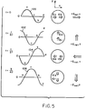
- Each of the waveforms 100, 102, 104 and 106 represents the voltages at helical couplers 80, 82, 84 and 86 (coils a, b, c and d, respectively) at intervals of one-quarter cycle of the high frequency power.
- the voltages applied to couplers 84 and 86 are zero, and there is no electric field along the Y axis (axis 92).
- a similar analysis shows that the net electric field rotates to the positive Y direction after one-quarter cycle, to the negative X direction after one-half cycle and to the negative Y direction after three quarters of a cycle. Thus, the net electric field rotates at the frequency of the applied high frequency power.
- the magnitude of the net electric field is constant because equal amplitude voltages are applied to the helical couplers 80, 82, 84 and 86.
- the electric field vector E net shown in FIG. 5 rotates in the plane of the helical couplers 80, 82, 84 and 86.
- FIG. 6 An example of an electrodeless high intensity discharge lamp in accordance with the present invention is shown in FIG. 6.
- a lamp capsule 130 is energized by helical couplers 132, 134, 136 and 138 as described above in connection with FIGS. 4 and 5.
- the lamp capsule 130 has a spherical shape with an inside diameter of 5 mm and a fill material comprising 2.6 mg of mercury with 0.26 mg of Na-Sc-iodide and 5 torr of argon gas.
- the helical couplers 132, 134, 136 and 138 are made from 0.025 inch diameter nickel wire.
- the coil inner diameter is 5 mm, the pitch is 1.46 mm, and the coil has 5.2 turns.
- a high frequency source 140 supplies power at a frequency of 915 MHz.
- a power splitter and phase shifter 142 is fabricated on microstrip transmission line and includes a first branch line quadrature hybrid coupler 144, a second branch line quadrature hybrid coupler 146 and a third branch line quadrature hybrid coupler 148.
- Each hybrid coupler includes a square pattern of conductors having sides that are approximately one-quarter of the guide wavelength at the center frequency of source 140.
- the construction of microstrip quadrature hybrid couplers is known generally in the art.
- Each quadrature hybrid coupler has two outputs with equal amplitudes and a 90° phase shift. The outputs of coupler 144 on lines 150 and 152 are supplied to the inputs of couplers 146 and 148, respectively.
- Line 150 is approximately one-quarter of a guide wavelength longer than line 152 at the center frequency of source 140 to ensure a 180° phase difference between the inputs to couplers 146 and 148.
- the outputs of quadrature hybrid coupler 146 are connected to helical couplers 132 and 136.
- the outputs of quadrature hybrid coupler 148 are connected to helical couplers 134 and 138.
- the isolation port of each quadrature hybrid coupler is terminated in a 50 ohm resistor 156.
- dielectric material such as Isoclad* GR6 ceramic-filled random glass microfiber-reinforced PTFE composite laminate or BeO having an approximate relative dielectric constant of 6 and having a thickness of 0.050 inch.
- a ground plane conductor is formed on the opposite side of the dielectric material.
- the lamp produced a spherically-shaped plasma and ran stably between 60 and 100 watts.
- the photometric brightness or luminance of the source was measured as 47 candela/mm2.
- the power splitter and phase shifter 22 provides a high degree of isolation between the lamp capsule 10 and the high frequency source 20.
- the plasma in the lamp capsule is not matched to the circuit that applies high frequency power to the lamp.
- significant high frequency power may be reflected by the lamp capsule and may potentially damage the high frequency source.
- the lamp capsule and the source are isolated, thus avoiding potential damage to the source during starting and warmup.
- any reflected power is dissipated in resistors 156 and does not reach high frequency source 140.
- the source effectively sees a constant load impedance.
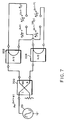
- FIG. 7 A block diagram of a first embodiment of the power splitter and phase shifter 22 is shown in FIG. 7.
- the output of high frequency source 20 is supplied to a quadrature hybrid coupler 200.
- the quadrature hybrid coupler produces two outputs of equal amplitude, which are phase shifted by 90°.
- a first output of coupler 200 is input to a half wave balun 202, and a second output of coupler 200 is input to a half wave balun 204.
- Each half wave balun produces two outputs of equal amplitude, which are phase shifted by 180°.
- the outputs of each half wave balun 202 and 204 are supplied to electric field applicators on opposite sides of the lamp capsule so as to produce a rotating electric field as described above.
- the half wave balun is described in detail in the aforementioned Patent No. 5,070,277.
- a second embodiment of the power splitter and phase shifter 22 is shown in FIG. 8.
- the output of high frequency source 20 is supplied to a 180° hybrid coupler 220.
- the 180° hybrid coupler generates two outputs of equal amplitude, which are phase shifted by 180°.
- a first output of coupler 220 is input to a quadrature hybrid coupler 222.
- a second output of coupler 220 is input to a quadrature hybrid coupler 224.
- the outputs of the quadrature hybrid couplers 222 and 224 are supplied to the electric field applicators 12, 14, 16 and 18 so as to produce a rotating electric field as described above.
- a third embodiment of the power splitter and phase shifter 22 is shown in FIG. 9.
- the output of high frequency source 20 is supplied to a quadrature hybrid coupler 240.
- a first output of coupler 240 is input to a 180° hybrid coupler 242, and a second output of hybrid coupler 240 is input to a 180° hybrid coupler 244.
- the outputs of each 180° hybrid coupler 242 and 244 are connected to electric field applicators on opposite sides of the lamp capsule so as to produce a rotating electric field as described above.
- FIG. 10 A fourth embodiment of the power splitter and phase shifter 22 is shown in FIG. 10.
- the electrodeless high intensity discharge lamp shown in FIG. 6 utilizes the configuration of FIG. 10.
- the output of high frequency source 20 is supplied to a quadrature hybrid coupler 260.
- a first output of coupler 260 is input to a quadrature hybrid coupler 262 through a transmission line 261 that is approximately one quarter of a guide wavelength longer than a transmission line 263 that connects a second output of coupler 260 to a quadrature hybrid coupler 264.
- the outputs of quadrature hybrid couplers 262 and 262 are coupled to electric field applicators 12, 14, 16 and 18 so as to produce a rotating electric field as described above.
- the power splitter and phase shifter configurations shown in FIGS. 7-10 and described above are preferably fabricated as microstrip transmission lines for simplicity, small size and low cost. To provide a more compact geometry, multilayer microstrip transmission lines can be utilized where appropriate. In each configuration, the unused inputs of the couplers are terminated by resistors so as to insure isolation between the lamp capsule and the source as described above.
- FIGS. 7-10 Multiple embodiments of the power splitter and phase shifter are shown in FIGS. 7-10 and described above. Additional configurations can be utilized which supply the required amplitude and phase to each of the electric field applicators to produce a rotating electric field within the lamp capsule. Furthermore, any electric field applicator capable of producing the required electric fields within the lamp capsule can be utilized. In general, the combination of the power splitter and phase shifter and the electric field applicators must produce a rotating electric field within the lamp capsule. While the electrodeless HID lamp of the present invention has been described as having four applicators, other numbers of applicators can be utilized, with appropriate changes to the positions of the applicators and the phases of the voltages applied to the applicators. For example, three applicators can be spaced at 120° intervals around the lamp capsule. In this case, the voltages applied to the three applicators are phase shifted by 120° relative to each other.
Landscapes
- Physics & Mathematics (AREA)
- Engineering & Computer Science (AREA)
- Plasma & Fusion (AREA)
- Electromagnetism (AREA)
- Discharge Lamps And Accessories Thereof (AREA)
- Circuit Arrangements For Discharge Lamps (AREA)
- Non-Portable Lighting Devices Or Systems Thereof (AREA)
Applications Claiming Priority (2)
| Application Number | Priority Date | Filing Date | Title |
|---|---|---|---|
| US248921 | 1994-05-24 | ||
| US08/248,921 US5498928A (en) | 1994-05-24 | 1994-05-24 | Electrodeless high intensity discharge lamp energized by a rotating electric field |
Publications (2)
| Publication Number | Publication Date |
|---|---|
| EP0684629A1 true EP0684629A1 (fr) | 1995-11-29 |
| EP0684629B1 EP0684629B1 (fr) | 2001-12-05 |
Family
ID=22941267
Family Applications (1)
| Application Number | Title | Priority Date | Filing Date |
|---|---|---|---|
| EP95108026A Expired - Lifetime EP0684629B1 (fr) | 1994-05-24 | 1995-05-24 | Lampe à décharge à haute intensité sans électrodes alimentée par un champ électrique tournant |
Country Status (6)
| Country | Link |
|---|---|
| US (1) | US5498928A (fr) |
| EP (1) | EP0684629B1 (fr) |
| JP (1) | JPH0855688A (fr) |
| KR (1) | KR100417341B1 (fr) |
| CA (1) | CA2149938C (fr) |
| DE (1) | DE69524286T2 (fr) |
Cited By (6)
| Publication number | Priority date | Publication date | Assignee | Title |
|---|---|---|---|---|
| EP0840354A3 (fr) * | 1996-11-01 | 1998-09-23 | Matsushita Electric Industrial Co., Ltd. | Moyens d'alimentation en énergie d'une décharge haute fréquence et dispositif de lampe à décharge haute fréquence sans électrode |
| EP0920240A3 (fr) * | 1997-11-28 | 2000-01-05 | Matsushita Electric Industrial Co., Ltd. | Alimentation en énergie haute fréquence et lampe sans électrodes à haute fréquence |
| EP0988639A4 (fr) * | 1997-05-21 | 2000-03-29 | Fusion Lighting Inc | Lampe sans electrode, non rotative, contenant une substance de remplissage moleculaire |
| WO2001003476A1 (fr) * | 1999-07-02 | 2001-01-11 | Fusion Lighting, Inc. | Lampes sans electrodes a induction et a champ electrique tournant |
| US6274984B1 (en) | 1997-10-30 | 2001-08-14 | Matsushita Electric Industrial Co., Ltd. | High-frequency energy supply means, and a high-frequency electrodeless discharge lamp device using side resonator coupling |
| WO2002082501A1 (fr) * | 2001-04-05 | 2002-10-17 | Fusion Lighting, Inc. | Lampes a decharge sans electrode et ampoule contenant du souffre, du selenium ou du tellurium |
Families Citing this family (22)
| Publication number | Priority date | Publication date | Assignee | Title |
|---|---|---|---|---|
| US5914564A (en) * | 1994-04-07 | 1999-06-22 | The Regents Of The University Of California | RF driven sulfur lamp having driving electrodes which face each other |
| US5545953A (en) * | 1995-06-16 | 1996-08-13 | Osram Sylvania Inc. | Electrodeless high intensity discharge lamp having field symmetrizing aid |
| US5861706A (en) * | 1997-06-10 | 1999-01-19 | Osram Sylvania Inc. | Electrodeless high intensity discharge medical lamp |
| US6084348A (en) * | 1997-08-13 | 2000-07-04 | Fusion Lighting, Inc. | Lamp having specific fill providing reduced restrike time |
| US5886479A (en) * | 1997-11-13 | 1999-03-23 | Northrop Grumman Corporation | Precession of the plasma torus in electrodeless lamps by non-mechanical means |
| US6137237A (en) | 1998-01-13 | 2000-10-24 | Fusion Lighting, Inc. | High frequency inductive lamp and power oscillator |
| US6313587B1 (en) | 1998-01-13 | 2001-11-06 | Fusion Lighting, Inc. | High frequency inductive lamp and power oscillator |
| US6107752A (en) * | 1998-03-03 | 2000-08-22 | Osram Sylvania Inc. | Coaxial applicators for electrodeless high intensity discharge lamps |
| US6239553B1 (en) * | 1999-04-22 | 2001-05-29 | Applied Materials, Inc. | RF plasma source for material processing |
| KR100393815B1 (ko) * | 2001-09-19 | 2003-08-02 | 엘지전자 주식회사 | 표면처리된 공진기를 가지는 무전극 조명기기 |
| US6566817B2 (en) * | 2001-09-24 | 2003-05-20 | Osram Sylvania Inc. | High intensity discharge lamp with only one electrode |
| US7305020B2 (en) * | 2002-02-04 | 2007-12-04 | Vizionware, Inc. | Method and system of reducing electromagnetic interference emissions |
| US7360936B2 (en) * | 2003-06-10 | 2008-04-22 | Abu-Ageel Nayef M | Method and system of LED light extraction using optical elements |
| US7400805B2 (en) * | 2003-06-10 | 2008-07-15 | Abu-Ageel Nayef M | Compact light collection system and method |
| US20070103645A1 (en) * | 2005-11-01 | 2007-05-10 | Seiko Epson Corporation | Projector |
| US20080030974A1 (en) * | 2006-08-02 | 2008-02-07 | Abu-Ageel Nayef M | LED-Based Illumination System |
| US20090050905A1 (en) * | 2007-08-20 | 2009-02-26 | Abu-Ageel Nayef M | Highly Efficient Light-Emitting Diode |
| GB2469186B (en) * | 2009-03-31 | 2013-09-11 | Karlsruher Inst Fur Technologie | A delay line for applicators of electrodeless gas discharge lamps |
| KR20100109500A (ko) * | 2009-03-31 | 2010-10-08 | 오스람 게젤샤프트 미트 베쉬랭크터 하프퉁 | 무전극 가스 방전 램프들의 동작을 위한 장 어플리케이터들에 대한 콤팩트한 지연 라인 구조들 |
| GB2469187A (en) * | 2009-04-01 | 2010-10-06 | Osram Ges Mit Beschrankter | An electrodeless high intensity discharge lamp |
| US9461222B1 (en) | 2015-06-30 | 2016-10-04 | Epistar Corporation | Light-emitting element and the light-emitting module thereof |
| JP2018181777A (ja) * | 2017-04-20 | 2018-11-15 | イマジニアリング株式会社 | 無電極ランプ |
Citations (15)
| Publication number | Priority date | Publication date | Assignee | Title |
|---|---|---|---|---|
| US3189901A (en) * | 1956-12-15 | 1965-06-15 | Giovanni Lanza | Method of producing ionization and luminous emission in a gas or vapor and apparatus for use therein |
| US4504768A (en) | 1982-06-30 | 1985-03-12 | Fusion Systems Corporation | Electrodeless lamp using a single magnetron and improved lamp envelope therefor |
| US4792732A (en) * | 1987-06-12 | 1988-12-20 | United States Of America As Represented By The Secretary Of The Air Force | Radio frequency plasma generator |
| US4803404A (en) | 1987-12-28 | 1989-02-07 | General Electric Company | Envelope for small high-intensity-discharge electrodeless arc lamp |
| US4887008A (en) | 1984-06-14 | 1989-12-12 | Fusion Systems Corporation | Electrodeless lamp bulb of modified shape for providing uniform emission of radiation |
| US4954755A (en) | 1982-05-24 | 1990-09-04 | Fusion Systems Corporation | Electrodeless lamp having hybrid cavity |
| EP0397421A2 (fr) * | 1989-05-08 | 1990-11-14 | General Electric Company | Lampe à décharge sans électrodes à hautes intensité et efficacité |
| US4975625A (en) | 1988-06-24 | 1990-12-04 | Fusion Systems Corporation | Electrodeless lamp which couples to small bulb |
| EP0457242A1 (fr) * | 1990-05-15 | 1991-11-21 | Osram Sylvania Inc. | Lampe de décharge à haute intensité sans électrode avec coupleur à raccorder à un générateur à micro-ondes |
| US5070277A (en) | 1990-05-15 | 1991-12-03 | Gte Laboratories Incorporated | Electrodless hid lamp with microwave power coupler |
| US5130612A (en) | 1991-09-11 | 1992-07-14 | Gte Products Corporation | Loop applicator for high frequency electrodeless lamps |
| US5144206A (en) | 1991-09-10 | 1992-09-01 | Gte Products Corporation | Electrodeless HID lamp coupling structure with integral matching network |
| EP0524001A1 (fr) * | 1991-07-18 | 1993-01-20 | Matra Marconi Space UK Limited | Coupleur micro-ondes multi-ports |
| US5227698A (en) | 1992-03-12 | 1993-07-13 | Fusion Systems Corporation | Microwave lamp with rotating field |
| DE4230029A1 (de) * | 1991-09-10 | 1993-08-05 | Gte Prod Corp | Becherfoermige endzufuehrungen fuer elektrodenlose hochfrequenzlampen |
Family Cites Families (6)
| Publication number | Priority date | Publication date | Assignee | Title |
|---|---|---|---|---|
| US3442758A (en) * | 1963-08-07 | 1969-05-06 | Litton Industries Inc | Containment of a plasma by a rotating magnetic field |
| US4749915A (en) * | 1982-05-24 | 1988-06-07 | Fusion Systems Corporation | Microwave powered electrodeless light source utilizing de-coupled modes |
| DE3942964A1 (de) * | 1989-12-23 | 1991-06-27 | Leybold Ag | Einrichtung fuer die erzeugung eines plasmas |
| US5280217A (en) * | 1992-08-14 | 1994-01-18 | Gte Products Corporation | Apparatus for coupling energy to electrodeless lamp applicators |
| US5313144A (en) * | 1992-12-31 | 1994-05-17 | Osram Sylvania Inc. | Power balanced coupling structure for electrodeless discharge lamp |
| US5339008A (en) * | 1993-04-13 | 1994-08-16 | Osram Sylvania Inc. | Electromagnetic discharge appartus with dual power amplifiers |
-
1994
- 1994-05-24 US US08/248,921 patent/US5498928A/en not_active Expired - Lifetime
-
1995
- 1995-05-23 JP JP7146873A patent/JPH0855688A/ja active Pending
- 1995-05-23 CA CA002149938A patent/CA2149938C/fr not_active Expired - Fee Related
- 1995-05-23 KR KR1019950012891A patent/KR100417341B1/ko not_active Expired - Fee Related
- 1995-05-24 EP EP95108026A patent/EP0684629B1/fr not_active Expired - Lifetime
- 1995-05-24 DE DE69524286T patent/DE69524286T2/de not_active Expired - Lifetime
Patent Citations (17)
| Publication number | Priority date | Publication date | Assignee | Title |
|---|---|---|---|---|
| US3189901A (en) * | 1956-12-15 | 1965-06-15 | Giovanni Lanza | Method of producing ionization and luminous emission in a gas or vapor and apparatus for use therein |
| US4954755A (en) | 1982-05-24 | 1990-09-04 | Fusion Systems Corporation | Electrodeless lamp having hybrid cavity |
| US4504768A (en) | 1982-06-30 | 1985-03-12 | Fusion Systems Corporation | Electrodeless lamp using a single magnetron and improved lamp envelope therefor |
| US4887008A (en) | 1984-06-14 | 1989-12-12 | Fusion Systems Corporation | Electrodeless lamp bulb of modified shape for providing uniform emission of radiation |
| US4792732A (en) * | 1987-06-12 | 1988-12-20 | United States Of America As Represented By The Secretary Of The Air Force | Radio frequency plasma generator |
| US4803404A (en) | 1987-12-28 | 1989-02-07 | General Electric Company | Envelope for small high-intensity-discharge electrodeless arc lamp |
| US4975625A (en) | 1988-06-24 | 1990-12-04 | Fusion Systems Corporation | Electrodeless lamp which couples to small bulb |
| US4972120A (en) | 1989-05-08 | 1990-11-20 | General Electric Company | High efficacy electrodeless high intensity discharge lamp |
| EP0397421A2 (fr) * | 1989-05-08 | 1990-11-14 | General Electric Company | Lampe à décharge sans électrodes à hautes intensité et efficacité |
| EP0457242A1 (fr) * | 1990-05-15 | 1991-11-21 | Osram Sylvania Inc. | Lampe de décharge à haute intensité sans électrode avec coupleur à raccorder à un générateur à micro-ondes |
| US5070277A (en) | 1990-05-15 | 1991-12-03 | Gte Laboratories Incorporated | Electrodless hid lamp with microwave power coupler |
| EP0524001A1 (fr) * | 1991-07-18 | 1993-01-20 | Matra Marconi Space UK Limited | Coupleur micro-ondes multi-ports |
| US5144206A (en) | 1991-09-10 | 1992-09-01 | Gte Products Corporation | Electrodeless HID lamp coupling structure with integral matching network |
| DE4230029A1 (de) * | 1991-09-10 | 1993-08-05 | Gte Prod Corp | Becherfoermige endzufuehrungen fuer elektrodenlose hochfrequenzlampen |
| US5241246A (en) | 1991-09-10 | 1993-08-31 | Gte Laboratories Incorporated | End cup applicators for high frequency electrodeless lamps |
| US5130612A (en) | 1991-09-11 | 1992-07-14 | Gte Products Corporation | Loop applicator for high frequency electrodeless lamps |
| US5227698A (en) | 1992-03-12 | 1993-07-13 | Fusion Systems Corporation | Microwave lamp with rotating field |
Cited By (8)
| Publication number | Priority date | Publication date | Assignee | Title |
|---|---|---|---|---|
| EP0840354A3 (fr) * | 1996-11-01 | 1998-09-23 | Matsushita Electric Industrial Co., Ltd. | Moyens d'alimentation en énergie d'une décharge haute fréquence et dispositif de lampe à décharge haute fréquence sans électrode |
| CN1104739C (zh) * | 1996-11-01 | 2003-04-02 | 松下电器产业株式会社 | 高频放电能量提供装置和高频无电极放电灯装置 |
| EP0988639A4 (fr) * | 1997-05-21 | 2000-03-29 | Fusion Lighting Inc | Lampe sans electrode, non rotative, contenant une substance de remplissage moleculaire |
| US6476557B1 (en) | 1997-05-21 | 2002-11-05 | Fusion Lighting, Inc. | Non-rotating electrodeless lamp containing molecular fill |
| US6274984B1 (en) | 1997-10-30 | 2001-08-14 | Matsushita Electric Industrial Co., Ltd. | High-frequency energy supply means, and a high-frequency electrodeless discharge lamp device using side resonator coupling |
| EP0920240A3 (fr) * | 1997-11-28 | 2000-01-05 | Matsushita Electric Industrial Co., Ltd. | Alimentation en énergie haute fréquence et lampe sans électrodes à haute fréquence |
| WO2001003476A1 (fr) * | 1999-07-02 | 2001-01-11 | Fusion Lighting, Inc. | Lampes sans electrodes a induction et a champ electrique tournant |
| WO2002082501A1 (fr) * | 2001-04-05 | 2002-10-17 | Fusion Lighting, Inc. | Lampes a decharge sans electrode et ampoule contenant du souffre, du selenium ou du tellurium |
Also Published As
| Publication number | Publication date |
|---|---|
| DE69524286T2 (de) | 2002-05-23 |
| US5498928A (en) | 1996-03-12 |
| JPH0855688A (ja) | 1996-02-27 |
| DE69524286D1 (de) | 2002-01-17 |
| CA2149938C (fr) | 2004-09-14 |
| KR950034399A (ko) | 1995-12-28 |
| CA2149938A1 (fr) | 1995-11-25 |
| KR100417341B1 (ko) | 2004-05-20 |
| EP0684629B1 (fr) | 2001-12-05 |
Similar Documents
| Publication | Publication Date | Title |
|---|---|---|
| US5498928A (en) | Electrodeless high intensity discharge lamp energized by a rotating electric field | |
| US5786667A (en) | Electrodeless lamp using separate microwave energy resonance modes for ignition and operation | |
| US4975625A (en) | Electrodeless lamp which couples to small bulb | |
| EP0840354B1 (fr) | Moyens d'alimentation en énergie d'une décharge haute fréquence et dispositif de lampe à décharge haute fréquence sans électrode | |
| US5113121A (en) | Electrodeless HID lamp with lamp capsule | |
| JP5033263B2 (ja) | 外部接地プローブを有する無電極ランプおよび改良型のバルブアセンブリ | |
| US8169152B2 (en) | Plasma lamp with field-concentrating antenna | |
| CA1149078A (fr) | Source compacte de lumiere fluorescente a electrodes metallisees | |
| US8629616B2 (en) | Arc tube device and stem structure for electrodeless plasma lamp | |
| JP2977949B2 (ja) | マイクロ波電力カプラーを有する無電極型hidランプ | |
| US9236238B2 (en) | Electrodeless lamps with coaxial type resonators/waveguides and grounded coupling elements | |
| US20130113374A1 (en) | Electrodeless lamps with grounded coupling elements | |
| US20020180356A1 (en) | Sulfur lamp | |
| US6107752A (en) | Coaxial applicators for electrodeless high intensity discharge lamps | |
| CN202285229U (zh) | 等离子体灯设备 | |
| EP0749152B1 (fr) | Lampe à décharge de grande puissance sans électrode pourvue d'un dispositif permettant de rendre le champ symétrique | |
| CN102122602A (zh) | 具有接地耦合元件及改进灯泡组件的无电极灯 | |
| US9177779B1 (en) | Low profile electrodeless lamps with an externally-grounded probe | |
| CA2208881C (fr) | Bloc refractaire maintenant l'enceinte d'une lampe sans electrode principale | |
| Gilliard et al. | Longitudinally mounted light emitting plasma in a dielectric resonator | |
| JP2011060505A (ja) | マイクロ波ランプ用の筐体、マイクロ波ランプ、光源装置、プロジェクター |
Legal Events
| Date | Code | Title | Description |
|---|---|---|---|
| PUAI | Public reference made under article 153(3) epc to a published international application that has entered the european phase |
Free format text: ORIGINAL CODE: 0009012 |
|
| AK | Designated contracting states |
Kind code of ref document: A1 Designated state(s): BE DE FR GB IT NL |
|
| 17P | Request for examination filed |
Effective date: 19960528 |
|
| 17Q | First examination report despatched |
Effective date: 19960809 |
|
| GRAG | Despatch of communication of intention to grant |
Free format text: ORIGINAL CODE: EPIDOS AGRA |
|
| GRAG | Despatch of communication of intention to grant |
Free format text: ORIGINAL CODE: EPIDOS AGRA |
|
| GRAH | Despatch of communication of intention to grant a patent |
Free format text: ORIGINAL CODE: EPIDOS IGRA |
|
| GRAH | Despatch of communication of intention to grant a patent |
Free format text: ORIGINAL CODE: EPIDOS IGRA |
|
| GRAA | (expected) grant |
Free format text: ORIGINAL CODE: 0009210 |
|
| AK | Designated contracting states |
Kind code of ref document: B1 Designated state(s): BE DE FR GB IT NL |
|
| REG | Reference to a national code |
Ref country code: GB Ref legal event code: IF02 |
|
| REF | Corresponds to: |
Ref document number: 69524286 Country of ref document: DE Date of ref document: 20020117 |
|
| ET | Fr: translation filed | ||
| PLBE | No opposition filed within time limit |
Free format text: ORIGINAL CODE: 0009261 |
|
| STAA | Information on the status of an ep patent application or granted ep patent |
Free format text: STATUS: NO OPPOSITION FILED WITHIN TIME LIMIT |
|
| 26N | No opposition filed | ||
| PGFP | Annual fee paid to national office [announced via postgrant information from national office to epo] |
Ref country code: DE Payment date: 20130522 Year of fee payment: 19 Ref country code: GB Payment date: 20130521 Year of fee payment: 19 |
|
| PGFP | Annual fee paid to national office [announced via postgrant information from national office to epo] |
Ref country code: FR Payment date: 20130603 Year of fee payment: 19 Ref country code: BE Payment date: 20130521 Year of fee payment: 19 Ref country code: IT Payment date: 20130529 Year of fee payment: 19 Ref country code: NL Payment date: 20130521 Year of fee payment: 19 |
|
| REG | Reference to a national code |
Ref country code: DE Ref legal event code: R119 Ref document number: 69524286 Country of ref document: DE |
|
| REG | Reference to a national code |
Ref country code: NL Ref legal event code: V1 Effective date: 20141201 |
|
| GBPC | Gb: european patent ceased through non-payment of renewal fee |
Effective date: 20140524 |
|
| PG25 | Lapsed in a contracting state [announced via postgrant information from national office to epo] |
Ref country code: NL Free format text: LAPSE BECAUSE OF NON-PAYMENT OF DUE FEES Effective date: 20141201 |
|
| REG | Reference to a national code |
Ref country code: FR Ref legal event code: ST Effective date: 20150130 |
|
| REG | Reference to a national code |
Ref country code: DE Ref legal event code: R119 Ref document number: 69524286 Country of ref document: DE Effective date: 20141202 |
|
| PG25 | Lapsed in a contracting state [announced via postgrant information from national office to epo] |
Ref country code: DE Free format text: LAPSE BECAUSE OF NON-PAYMENT OF DUE FEES Effective date: 20141202 Ref country code: IT Free format text: LAPSE BECAUSE OF NON-PAYMENT OF DUE FEES Effective date: 20140524 |
|
| PG25 | Lapsed in a contracting state [announced via postgrant information from national office to epo] |
Ref country code: GB Free format text: LAPSE BECAUSE OF NON-PAYMENT OF DUE FEES Effective date: 20140524 Ref country code: FR Free format text: LAPSE BECAUSE OF NON-PAYMENT OF DUE FEES Effective date: 20140602 |
|
| PG25 | Lapsed in a contracting state [announced via postgrant information from national office to epo] |
Ref country code: BE Free format text: LAPSE BECAUSE OF NON-PAYMENT OF DUE FEES Effective date: 20140531 |