EP0685154A1 - Machine for marking hard-rind matured cheese, such as parmesan - Google Patents
Machine for marking hard-rind matured cheese, such as parmesan Download PDFInfo
- Publication number
- EP0685154A1 EP0685154A1 EP95201232A EP95201232A EP0685154A1 EP 0685154 A1 EP0685154 A1 EP 0685154A1 EP 95201232 A EP95201232 A EP 95201232A EP 95201232 A EP95201232 A EP 95201232A EP 0685154 A1 EP0685154 A1 EP 0685154A1
- Authority
- EP
- European Patent Office
- Prior art keywords
- cheese
- plate
- whole
- machine
- rotary plate
- Prior art date
- Legal status (The legal status is an assumption and is not a legal conclusion. Google has not performed a legal analysis and makes no representation as to the accuracy of the status listed.)
- Granted
Links
Images


Classifications
-
- A—HUMAN NECESSITIES
- A01—AGRICULTURE; FORESTRY; ANIMAL HUSBANDRY; HUNTING; TRAPPING; FISHING
- A01J—MANUFACTURE OF DAIRY PRODUCTS
- A01J27/00—After-treatment of cheese; Coating of cheese
- A01J27/005—Marking cheese
Definitions
- One of these consists of marking the whole cheese while still fresh, this being done by providing the mould containing the fresh cheese mass with suitable inscriptions in relief.
- the other consists of applying an incandescent marker which melts the rind and can be applied to a hard-rind cheese at an advanced stage of its maturing.
- Fresh marking can be applied only to fresh whole cheeses as stated, and hence certifies only the origin of the product, and not its quality.
- this type of difficultly erasable permanent marking can also mark products not of highest quality, or even defective.
- Hot marking can only be applied to limited regions of the whole cheese surface, and is hence unsuitable for marking those portions of a whole cheese having their surface distant from the markings. This has proved inadequate, in particular in the light of the recent tendency to sell small vacuum-packed portions of a whole cheese.
- Said machine must also be of small dimensions so that it can be easily transported from one maturing store to another and be installed, and further be easily moved from one region to another of the same store.
- the object of the present patent is to provide a machine satisfying the aforesaid requirements.
- This object is attained according to the invention by a machine which acts on the surface or rind of the whole cheese by means of a laser beam guided in synchronism with the rotation of the whole cheese.
- the machine according to the invention comprises means for receiving the whole cheese to be marked, means for perfectly centering the whole cheese, means for rotating it in front of a laser beam, and means for guiding the beam along perpendicular axes in accordance with a graphic program executed by a computer.
- the figures show a frame structure 1 mounted on wheels 2 and having its rear region closed by a cover 3 hinged on the vertical axis 4, and its front region closed upperly by a cover 5 hinged on the horizontal axis 6.
- the cover 5 is counterbalanced by a pneumatic spring 9.
- the structure is masked on its sides by panels 7.
- the cover 3 has an upper shelf 10 enclosed within a small cover 8 hinged horizontally at 11, and on which a control keyboard rests.
- the front part of the machine comprises the means for retaining, centering and moving the whole cheese.
- the slide 16 carries three pins 20 positioned 60° apart in accordance with the sides of an equilateral triangle on which there rock three levers 21 carrying at their top three pads 22 for centering the whole cheese resting on the plate 13.
- the lower part 210 is hinged to the pin 20 and comprises an appendix 214 which extends virtually radially below a disc 23 coaxial to the plate 13, which can move vertically.
- the lower part 214 is maintained against the disc 23 by the spring 215.
- the disc 23 is urged elastically upwards, and is pushed downwards by an appendix 24 keyed onto the shaft 25 and maintained in contact with the disc 23 by a spring 26.
- the shaft 25 extends to the outside of the structure 1 where it carries an operating lever 26 (see Figure 4).
- the lower part 210 also carries a pinion 211 the shaft 121 of which extends to the outside of the structure, where it carries the operating lever 27 (see Figure 4).
- the upper part 212 carrying the pad 22 slides within the lower part 210.
- the part 212 comprises a rack 213 which engages the pinion 211.
- the other two levers 21 both have an appendix similar to 214 extending below the disc 23, which simultaneously operates all three levers.
- the laser device schematically indicated by 28 is located in the rear region of the frame 1 ( Figure 3).
- a feed carriage and a galvanometric beam deflection system controlled by a miniprocessor such as a personal computer which, by virtue of the graphic program, enables the design to be reproduced on the moving whole cheese to be marked.
- system bus of the personal computer comprises two 12 bit D/A (digital/analog) converters (hence with resolution of 1 in 4096) to generate two voltages between -5V and +5V controlling the position of the X and Y axes of the laser beam.
- Said voltages of +5V and -5V correspond to the ends of the useful marking area both for the X axis and for the Y axis.
- the marking area on the cylindrical-convex surface of the whole cheese 30 can be set by the handwheel 18 or motor unit 118.
- the program has to generate moment by moment suitably synchronized and timed voltages appropriate for positioning the beam at the desired X and Y coordinates.
- model 5D 1203 12 bit D/A converter was used of a type suitable for insertion into one of the 8 or 16 bit slots provided in the personal computer bus.
- the aforedescribed laser system is currently produced by SYNRAD INC., 91816 North Creek Pkwy N No. 103, Bothwell, Wa 98011 - 8205 USA, and is well known to the expert of the art so that a detailed description thereof will not be given.
- the invention operates as follows: having arranged the whole cheese 30 to be marked on the plate 13, the lever 27 is firstly operated to raise the upper part 212 of the front lever 21, and then the lever 24 to operate the three levers 21 which perfectly centre the whole cheese on the plate 13 by means of the pads 22.
- the cover 5 is lowered and the motor 118, by operating the threaded rod 19, moves the slide into the position in which the whole cheese 30 is at the correct distance from the laser generator.
- the computer-controlled system is then operated to rotate the plate 13 and simultaneously oscillate the laser beam and generate distinctive designs distributed peripherally over the entire development of the cylindrical-convex part of the whole cheese 30.
- the safety devices, operation enabling devices and cycle control devices are not described as these can be easily implemented in various ways by an expert of the art on the basis of the aforegoing information.
Landscapes
- Life Sciences & Earth Sciences (AREA)
- Animal Husbandry (AREA)
- Environmental Sciences (AREA)
- Dairy Products (AREA)
- Laser Beam Processing (AREA)
- Packging For Living Organisms, Food Or Medicinal Products That Are Sensitive To Environmental Conditiond (AREA)
- Treatment Of Fiber Materials (AREA)
Abstract
Description
- The surface of whole cheeses produced by cooperatives is required under their regulations to carry a recognition mark, which is generally the mark of the particular cooperative concerned.
- Whole cheeses are currently marked by two different methods.
- One of these consists of marking the whole cheese while still fresh, this being done by providing the mould containing the fresh cheese mass with suitable inscriptions in relief. The other consists of applying an incandescent marker which melts the rind and can be applied to a hard-rind cheese at an advanced stage of its maturing.
- Both these marking methods suffer from drawbacks.
- Fresh marking can be applied only to fresh whole cheeses as stated, and hence certifies only the origin of the product, and not its quality.
- In this respect, as quality defects can come to light during maturing, this type of difficultly erasable permanent marking can also mark products not of highest quality, or even defective.
- Hot marking can only be applied to limited regions of the whole cheese surface, and is hence unsuitable for marking those portions of a whole cheese having their surface distant from the markings. This has proved inadequate, in particular in the light of the recent tendency to sell small vacuum-packed portions of a whole cheese.
- A requirement has therefore existed for some time, especially in the field of Parmesan cheese cooperatives, for applying a mark to the whole cheese when in an advanced state of maturing, the mark being restricted only to those whole cheeses which have passed strict quality control and being applied to the entire surface of the whole cheese or at least to its cylindrical-convex surface.
- Obviously said mark must be able to be used to obliterate an existing mark.
- Said machine must also be of small dimensions so that it can be easily transported from one maturing store to another and be installed, and further be easily moved from one region to another of the same store.
- The object of the present patent is to provide a machine satisfying the aforesaid requirements.
- This object is attained according to the invention by a machine which acts on the surface or rind of the whole cheese by means of a laser beam guided in synchronism with the rotation of the whole cheese.
- The application of laser technology to the scoring of a relatively soft low-melting surface such as the rind of a matured hard cheese has required not only the overcoming of certain radical prejudices according to which it has been previously considered impossible to score surfaces of low-melting soft material with a laser beam in a controlled manner, but also to solve subordinate problems by devising expedients which overall cooperate in achieving the result, as will be apparent hereinafter.
- The machine according to the invention comprises means for receiving the whole cheese to be marked, means for perfectly centering the whole cheese, means for rotating it in front of a laser beam, and means for guiding the beam along perpendicular axes in accordance with a graphic program executed by a computer.
- The operational and constructional characteristics and merits of the invention will be more apparent from the detailed description of a preferred embodiment thereof given hereinafter by way of non-limiting example with reference to the accompanying drawings.
- Figure 1 is a side view of the invention in its operating position.
- Figure 2 is a view of the invention from the opposite side in its rest position with its upper covers raised.
- Figure 3 is a plan view of the invention.
- Figure 4 is a plan view of the invention without the whole cheese support plate and the underlying protection plate.
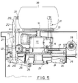
- Figure 5 is a partial section on the line V-V of Figure 5.
- The figures show a
frame structure 1 mounted onwheels 2 and having its rear region closed by acover 3 hinged on thevertical axis 4, and its front region closed upperly by acover 5 hinged on thehorizontal axis 6. Thecover 5 is counterbalanced by apneumatic spring 9. The structure is masked on its sides by panels 7. - The
cover 3 has anupper shelf 10 enclosed within asmall cover 8 hinged horizontally at 11, and on which a control keyboard rests. - The front part of the machine comprises the means for retaining, centering and moving the whole cheese.
- As can be seen in Figures 3, 4 and 5 these consist of a
circular plate 13 supported horizontally by thevertical output shaft 14 of an electric gearedmotor unit 15. This latter is located on aslide 16 slidable along twocylindrical rods 17 under the control of a geared motor unit 118 (see Figure 1) which operates a threaded rod engaged in a seat in theslide 16. The said rod can be operated manually by thehandwheel 18. - The
slide 16 carries threepins 20 positioned 60° apart in accordance with the sides of an equilateral triangle on which there rock threelevers 21 carrying at their top threepads 22 for centering the whole cheese resting on theplate 13. - Two
levers 21 close to therear wall 23 of the compartment containing the plate 13 (see Figure 4) are composed of only one piece, whereas thethird lever 21, which rises centrally in front of the operator, is composed of two parts (see Figure 5). - The
lower part 210 is hinged to thepin 20 and comprises anappendix 214 which extends virtually radially below adisc 23 coaxial to theplate 13, which can move vertically. Thelower part 214 is maintained against thedisc 23 by thespring 215. - The
disc 23 is urged elastically upwards, and is pushed downwards by anappendix 24 keyed onto theshaft 25 and maintained in contact with thedisc 23 by aspring 26. - The
shaft 25 extends to the outside of thestructure 1 where it carries an operating lever 26 (see Figure 4). - The
lower part 210 also carries apinion 211 theshaft 121 of which extends to the outside of the structure, where it carries the operating lever 27 (see Figure 4). - The
upper part 212 carrying thepad 22 slides within thelower part 210. - The
part 212 comprises arack 213 which engages thepinion 211. - Operating the
lever 27 causes thepinion 211 to lower or raise thepart 212, which can hence free the space in front of theplate 13. - The other two
levers 21 both have an appendix similar to 214 extending below thedisc 23, which simultaneously operates all three levers. - The laser device schematically indicated by 28 is located in the rear region of the frame 1 (Figure 3).
- This is a Synrad model 57-1-28 sealed CO₂ laser well known to the expert of the art. It emits infrared radiation within the non-visible range at a wavelength of 10.6 µm with a max mean power of 100 W and has the following specification:
- wavelength: 10µm (nominal 10.6 µm)
- max mean power: 100 W (typical 120 W, minimum 90 W)
- power stability: ± 5%
- useful repetition frequency: 4 KHz
- polarization: vertical
- beam diameter: 4 mm
- beam divergence: 3.5 mR
- electrical power employed: 2.5 KVA
- electrical supply: 65A
- laser head dimensions: 958 x 114 x 160 mm
- approximate laser head weight: 15 kg.
- It comprises a water/air heat exchanger, indicated schematically by 29 (Figure 1), with a capacity of about 10 litres of water.
- There are also provided a feed carriage and a galvanometric beam deflection system controlled by a miniprocessor such as a personal computer which, by virtue of the graphic program, enables the design to be reproduced on the moving whole cheese to be marked.
- In this specific case the system bus of the personal computer comprises two 12 bit D/A (digital/analog) converters (hence with resolution of 1 in 4096) to generate two voltages between -5V and +5V controlling the position of the X and Y axes of the laser beam.
- Said voltages of +5V and -5V correspond to the ends of the useful marking area both for the X axis and for the Y axis.
- The marking area on the cylindrical-convex surface of the
whole cheese 30 can be set by thehandwheel 18 ormotor unit 118. - To make the laser beam follow a certain path (and hence reproduce a certain design), the program has to generate moment by moment suitably synchronized and timed voltages appropriate for positioning the beam at the desired X and Y coordinates.
- In the case described herein a model 5D 1203 12 bit D/A converter was used of a type suitable for insertion into one of the 8 or 16 bit slots provided in the personal computer bus.
- The aforedescribed laser system is currently produced by SYNRAD INC., 91816 North Creek Pkwy N No. 103, Bothwell, Wa 98011 - 8205 USA, and is well known to the expert of the art so that a detailed description thereof will not be given.
- The invention operates as follows: having arranged the
whole cheese 30 to be marked on theplate 13, thelever 27 is firstly operated to raise theupper part 212 of thefront lever 21, and then thelever 24 to operate the threelevers 21 which perfectly centre the whole cheese on theplate 13 by means of thepads 22. - Having done this the
cover 5 is lowered and themotor 118, by operating the threadedrod 19, moves the slide into the position in which thewhole cheese 30 is at the correct distance from the laser generator. The computer-controlled system is then operated to rotate theplate 13 and simultaneously oscillate the laser beam and generate distinctive designs distributed peripherally over the entire development of the cylindrical-convex part of thewhole cheese 30. - The safety devices, operation enabling devices and cycle control devices are not described as these can be easily implemented in various ways by an expert of the art on the basis of the aforegoing information.
Claims (5)
- A machine for marking an at least partly matured whole hard cheese, characterised by comprising a rotary plate (13) of vertical axis for receiving and supporting a whole cheese (30) to be marked; means (21, 22, 23) for centering the whole cheese on the rotary plate, means (15) for rotating the rotary plate, and a laser system (28) positioned to the side of the rotary plate in a manner orientated substantially towards the plate axis and provided with galvanometric deflector means for the laser beam, said plate rotating means (15) and said deflector means being controlled by a microprocessor provided with a graphic program such as to cause a desired design to be executed over the entire cylindrical-convex surface of the whole cheese.
- A machine as claimed in claim 1, characterised in that the rotary plate (13) and the relative means for rotating it and for centering the whole cheese are positioned on a slide (16) slidable on guides (17) and of which the distance from the laser beam source (29) is adjustable by means of a screw device (18, 19).
- A machine as claimed in claim 1, characterised in that the means for centering the whole cheese comprise a plate (23) coaxial with the shaft (14) and a geared motor (15) which rotates the vertically movable whole cheese (30), the vertical movements of which are generated by a lever (26) and cause three centering levers (21) to rotate in planes arranged 120° apart and converging at the axis of the shaft (14).
- A machine as claimed in claim 3, characterised in that at least one of the levers (21) is composed of two parts (210, 212) slidable one relative to the other and mutually engaged by rack (213) and pinion (211) means operable from the outside by a lever (27), such that the upper end of the part (212) can rise above the the plate (13) or descend approximately to the level thereof.
- A machine as claimed in claim 1, characterized in that the laser system (28) is a sealed CO₂ system, which emits an infrared beam in the non-visible range at a wavelength close to 10 µm with a mean power of 100 ± 0.05 W, and comprises a galvanometric system for deflection along two perpendicular axes controlled by a computer by means of a graphic program.
Applications Claiming Priority (2)
| Application Number | Priority Date | Filing Date | Title |
|---|---|---|---|
| IT94RE000030U IT234940Y1 (en) | 1994-06-01 | 1994-06-01 | MACHINE FOR THE MARKING OF AGED HARD RINDED CHEESE, SUCH AS PARMIGIANO-REGGIANO |
| ITRE940030U | 1994-06-01 |
Publications (3)
| Publication Number | Publication Date |
|---|---|
| EP0685154A1 true EP0685154A1 (en) | 1995-12-06 |
| EP0685154B1 EP0685154B1 (en) | 1997-11-26 |
| EP0685154B2 EP0685154B2 (en) | 2000-12-06 |
Family
ID=11398564
Family Applications (1)
| Application Number | Title | Priority Date | Filing Date |
|---|---|---|---|
| EP95201232A Expired - Lifetime EP0685154B2 (en) | 1994-06-01 | 1995-05-11 | Machine for marking hard-rind matured cheese, such as parmesan |
Country Status (4)
| Country | Link |
|---|---|
| EP (1) | EP0685154B2 (en) |
| AT (1) | ATE160482T1 (en) |
| DE (1) | DE69501096D1 (en) |
| IT (1) | IT234940Y1 (en) |
Cited By (3)
| Publication number | Priority date | Publication date | Assignee | Title |
|---|---|---|---|---|
| FR2870478A1 (en) * | 2004-05-19 | 2005-11-25 | Syndicat Interprofessionnel De | Cheese heel marker uses computer-controlled inkjet printer with cuurved head to apply food-grade ink to rough rind surface |
| NL1037562C2 (en) * | 2009-12-16 | 2011-06-20 | Kaamps Food Productions B V | METHOD FOR APPLYING AN INDICATION ON A CHEESE |
| IT202100003329A1 (en) * | 2021-02-15 | 2022-08-15 | Faber S R L | DEVICE AND METHOD OF ENGRAVING THE RIND OF HARD CHEESES |
Families Citing this family (1)
| Publication number | Priority date | Publication date | Assignee | Title |
|---|---|---|---|---|
| IT202000031460A1 (en) * | 2020-12-18 | 2022-06-18 | Form 5 S R L | MARKER TO GENERATE AN IMPRESSION ON A SURFACE TO BE MARKED |
Citations (2)
| Publication number | Priority date | Publication date | Assignee | Title |
|---|---|---|---|---|
| FR2621529A1 (en) * | 1987-10-09 | 1989-04-14 | Bongrain Sa | Method for thermal treatment of a food product, in particular a cheese or pork butchery food product; method for marking such a food product, marking apparatus for implementing the method; food product thus treated or marked |
| EP0421837A1 (en) * | 1989-10-04 | 1991-04-10 | Bongrain S.A. | Apparatus for marking the surface by laser of cheese or meat products |
Family Cites Families (4)
| Publication number | Priority date | Publication date | Assignee | Title |
|---|---|---|---|---|
| DD148610A1 (en) † | 1980-01-22 | 1981-06-03 | Ludwig Staedtler | MACHINE FOR DECORATING AND MARKING GLASS ARTICLES BY MEANS OF LASER RADIATION |
| US4564737A (en) † | 1983-07-11 | 1986-01-14 | F.M.P. Enterprise, Inc. | Automatic layout machine for tire tread patterns |
| CH679970A5 (en) † | 1988-10-28 | 1992-05-29 | Bongrain Sa | |
| DE3939866A1 (en) † | 1989-12-01 | 1991-06-06 | Baasel Carl Lasertech | Laser engraving device for workpiece cylindrical mantle surface - has annular focussing mirror with curved mirror surface |
-
1994
- 1994-06-01 IT IT94RE000030U patent/IT234940Y1/en active IP Right Grant
-
1995
- 1995-05-11 EP EP95201232A patent/EP0685154B2/en not_active Expired - Lifetime
- 1995-05-11 DE DE69501096T patent/DE69501096D1/en not_active Expired - Lifetime
- 1995-05-11 AT AT95201232T patent/ATE160482T1/en active
Patent Citations (2)
| Publication number | Priority date | Publication date | Assignee | Title |
|---|---|---|---|---|
| FR2621529A1 (en) * | 1987-10-09 | 1989-04-14 | Bongrain Sa | Method for thermal treatment of a food product, in particular a cheese or pork butchery food product; method for marking such a food product, marking apparatus for implementing the method; food product thus treated or marked |
| EP0421837A1 (en) * | 1989-10-04 | 1991-04-10 | Bongrain S.A. | Apparatus for marking the surface by laser of cheese or meat products |
Cited By (4)
| Publication number | Priority date | Publication date | Assignee | Title |
|---|---|---|---|---|
| FR2870478A1 (en) * | 2004-05-19 | 2005-11-25 | Syndicat Interprofessionnel De | Cheese heel marker uses computer-controlled inkjet printer with cuurved head to apply food-grade ink to rough rind surface |
| NL1037562C2 (en) * | 2009-12-16 | 2011-06-20 | Kaamps Food Productions B V | METHOD FOR APPLYING AN INDICATION ON A CHEESE |
| IT202100003329A1 (en) * | 2021-02-15 | 2022-08-15 | Faber S R L | DEVICE AND METHOD OF ENGRAVING THE RIND OF HARD CHEESES |
| EP4042863A1 (en) * | 2021-02-15 | 2022-08-17 | Faber S.r.l. | A device and method for carving the rind of hard cheeses |
Also Published As
| Publication number | Publication date |
|---|---|
| ITRE940030U1 (en) | 1995-12-01 |
| EP0685154B2 (en) | 2000-12-06 |
| ITRE940030V0 (en) | 1994-06-01 |
| EP0685154B1 (en) | 1997-11-26 |
| ATE160482T1 (en) | 1997-12-15 |
| IT234940Y1 (en) | 2000-03-20 |
| DE69501096D1 (en) | 1998-01-08 |
Similar Documents
| Publication | Publication Date | Title |
|---|---|---|
| AU2563884A (en) | Automated sign generator | |
| US5694823A (en) | Document trimming apparatus | |
| EP0685154B1 (en) | Machine for marking hard-rind matured cheese, such as parmesan | |
| JPH0375303B2 (en) | ||
| US3274736A (en) | Edge tooling apparatus | |
| US6218639B1 (en) | Plasma torch cutting system | |
| AU6244586A (en) | Bending press | |
| ITUD20110078A1 (en) | "AUTOMATIC SHARPENING MACHINE FOR WOODEN CANDLE MILLS, PROGRAMMABLE WITH OPTICAL READING OF THE GEOMETRIC CHARACTERISTICS AND COMPUTERIZED SHARPENING". | |
| US20200114436A1 (en) | Cnc sink aperture cutting machine and method | |
| US4097746A (en) | Driving and positioning arrangement for radiography | |
| JPH0857654A (en) | Plasma cutting device | |
| US4513649A (en) | Cutting vitrous sheet corners | |
| CN209757753U (en) | A shampoo production labeling machine | |
| ES2052972T3 (en) | CUTTING MACHINE FOR CUTTING FLAT MATERIAL. | |
| WO2003089999A1 (en) | Cutting device with synchronized calibration units | |
| JPH0377135B2 (en) | ||
| EP1057587A2 (en) | Machine for working sheets of glass and similar | |
| CN221603542U (en) | Deflection improving device of laser engraving machine | |
| US3783513A (en) | Carpet cutter | |
| CN223544886U (en) | Grinding tool adjusting mechanism for chamfering machine | |
| CN217224549U (en) | Marking machine for packaging vehicle-mounted navigation display screen | |
| US20230128066A1 (en) | Reconfigurable Single Media Printer Having a Positionable Media Support Carriage | |
| DE10251515B3 (en) | Sawing machine, especially rock saw, has contour controller detection device and supporting components mechanically coupled for synchronous transfer of feed movements | |
| NL1008757C2 (en) | Cutting machine for steel sheet. | |
| KR101433872B1 (en) | Character Cutting Device |
Legal Events
| Date | Code | Title | Description |
|---|---|---|---|
| PUAI | Public reference made under article 153(3) epc to a published international application that has entered the european phase |
Free format text: ORIGINAL CODE: 0009012 |
|
| AK | Designated contracting states |
Kind code of ref document: A1 Designated state(s): AT BE CH DE DK ES FR GB GR IE IT LI LU MC NL PT SE |
|
| RAX | Requested extension states of the european patent have changed |
Free format text: LT PAYMENT 950510;SI PAYMENT 950510 |
|
| 17P | Request for examination filed |
Effective date: 19960515 |
|
| 17Q | First examination report despatched |
Effective date: 19960702 |
|
| GRAG | Despatch of communication of intention to grant |
Free format text: ORIGINAL CODE: EPIDOS AGRA |
|
| GRAH | Despatch of communication of intention to grant a patent |
Free format text: ORIGINAL CODE: EPIDOS IGRA |
|
| GRAH | Despatch of communication of intention to grant a patent |
Free format text: ORIGINAL CODE: EPIDOS IGRA |
|
| GRAA | (expected) grant |
Free format text: ORIGINAL CODE: 0009210 |
|
| AK | Designated contracting states |
Kind code of ref document: B1 Designated state(s): AT BE CH DE DK ES FR GB GR IE IT LI LU MC NL PT SE |
|
| AX | Request for extension of the european patent |
Free format text: LT PAYMENT 950510;SI PAYMENT 950510 |
|
| PG25 | Lapsed in a contracting state [announced via postgrant information from national office to epo] |
Ref country code: NL Free format text: LAPSE BECAUSE OF FAILURE TO SUBMIT A TRANSLATION OF THE DESCRIPTION OR TO PAY THE FEE WITHIN THE PRESCRIBED TIME-LIMIT Effective date: 19971126 Ref country code: LI Free format text: LAPSE BECAUSE OF FAILURE TO SUBMIT A TRANSLATION OF THE DESCRIPTION OR TO PAY THE FEE WITHIN THE PRESCRIBED TIME-LIMIT Effective date: 19971126 Ref country code: GR Free format text: LAPSE BECAUSE OF FAILURE TO SUBMIT A TRANSLATION OF THE DESCRIPTION OR TO PAY THE FEE WITHIN THE PRESCRIBED TIME-LIMIT Effective date: 19971126 Ref country code: FR Free format text: LAPSE BECAUSE OF FAILURE TO SUBMIT A TRANSLATION OF THE DESCRIPTION OR TO PAY THE FEE WITHIN THE PRESCRIBED TIME-LIMIT Effective date: 19971126 Ref country code: ES Free format text: THE PATENT HAS BEEN ANNULLED BY A DECISION OF A NATIONAL AUTHORITY Effective date: 19971126 Ref country code: DK Free format text: LAPSE BECAUSE OF NON-PAYMENT OF DUE FEES Effective date: 19971126 Ref country code: CH Free format text: LAPSE BECAUSE OF FAILURE TO SUBMIT A TRANSLATION OF THE DESCRIPTION OR TO PAY THE FEE WITHIN THE PRESCRIBED TIME-LIMIT Effective date: 19971126 Ref country code: BE Free format text: LAPSE BECAUSE OF FAILURE TO SUBMIT A TRANSLATION OF THE DESCRIPTION OR TO PAY THE FEE WITHIN THE PRESCRIBED TIME-LIMIT Effective date: 19971126 Ref country code: AT Free format text: LAPSE BECAUSE OF FAILURE TO SUBMIT A TRANSLATION OF THE DESCRIPTION OR TO PAY THE FEE WITHIN THE PRESCRIBED TIME-LIMIT Effective date: 19971126 |
|
| REF | Corresponds to: |
Ref document number: 160482 Country of ref document: AT Date of ref document: 19971215 Kind code of ref document: T |
|
| REG | Reference to a national code |
Ref country code: CH Ref legal event code: EP |
|
| REF | Corresponds to: |
Ref document number: 69501096 Country of ref document: DE Date of ref document: 19980108 |
|
| ITF | It: translation for a ep patent filed | ||
| PG25 | Lapsed in a contracting state [announced via postgrant information from national office to epo] |
Ref country code: SE Free format text: LAPSE BECAUSE OF FAILURE TO SUBMIT A TRANSLATION OF THE DESCRIPTION OR TO PAY THE FEE WITHIN THE PRESCRIBED TIME-LIMIT Effective date: 19980226 Ref country code: PT Free format text: LAPSE BECAUSE OF FAILURE TO SUBMIT A TRANSLATION OF THE DESCRIPTION OR TO PAY THE FEE WITHIN THE PRESCRIBED TIME-LIMIT Effective date: 19980226 |
|
| PG25 | Lapsed in a contracting state [announced via postgrant information from national office to epo] |
Ref country code: DE Free format text: LAPSE BECAUSE OF FAILURE TO SUBMIT A TRANSLATION OF THE DESCRIPTION OR TO PAY THE FEE WITHIN THE PRESCRIBED TIME-LIMIT Effective date: 19980227 |
|
| EN | Fr: translation not filed | ||
| NLV1 | Nl: lapsed or annulled due to failure to fulfill the requirements of art. 29p and 29m of the patents act | ||
| PG25 | Lapsed in a contracting state [announced via postgrant information from national office to epo] |
Ref country code: LU Free format text: LAPSE BECAUSE OF NON-PAYMENT OF DUE FEES Effective date: 19980511 Ref country code: IE Free format text: LAPSE BECAUSE OF NON-PAYMENT OF DUE FEES Effective date: 19980511 |
|
| REG | Reference to a national code |
Ref country code: CH Ref legal event code: PL |
|
| PLBQ | Unpublished change to opponent data |
Free format text: ORIGINAL CODE: EPIDOS OPPO |
|
| PLBI | Opposition filed |
Free format text: ORIGINAL CODE: 0009260 |
|
| PLBF | Reply of patent proprietor to notice(s) of opposition |
Free format text: ORIGINAL CODE: EPIDOS OBSO |
|
| 26 | Opposition filed |
Opponent name: HOFMEISTER KAESEWERK GMBH & CO KG Effective date: 19980818 |
|
| PG25 | Lapsed in a contracting state [announced via postgrant information from national office to epo] |
Ref country code: MC Free format text: LAPSE BECAUSE OF NON-PAYMENT OF DUE FEES Effective date: 19981130 |
|
| PLBF | Reply of patent proprietor to notice(s) of opposition |
Free format text: ORIGINAL CODE: EPIDOS OBSO |
|
| PG25 | Lapsed in a contracting state [announced via postgrant information from national office to epo] |
Ref country code: GB Free format text: LAPSE BECAUSE OF NON-PAYMENT OF DUE FEES Effective date: 19990511 |
|
| GBPC | Gb: european patent ceased through non-payment of renewal fee |
Effective date: 19990511 |
|
| PLAW | Interlocutory decision in opposition |
Free format text: ORIGINAL CODE: EPIDOS IDOP |
|
| PLAW | Interlocutory decision in opposition |
Free format text: ORIGINAL CODE: EPIDOS IDOP |
|
| PUAH | Patent maintained in amended form |
Free format text: ORIGINAL CODE: 0009272 |
|
| STAA | Information on the status of an ep patent application or granted ep patent |
Free format text: STATUS: PATENT MAINTAINED AS AMENDED |
|
| 27A | Patent maintained in amended form |
Effective date: 20001206 |
|
| AK | Designated contracting states |
Kind code of ref document: B2 Designated state(s): AT BE CH DE DK ES FR GB GR IE IT LI LU MC NL PT SE |
|
| AX | Request for extension of the european patent |
Free format text: LT PAYMENT 19950510;SI PAYMENT 19950510 |
|
| ITF | It: translation for a ep patent filed | ||
| EN | Fr: translation not filed | ||
| PG25 | Lapsed in a contracting state [announced via postgrant information from national office to epo] |
Ref country code: IT Free format text: LAPSE BECAUSE OF NON-PAYMENT OF DUE FEES;WARNING: LAPSES OF ITALIAN PATENTS WITH EFFECTIVE DATE BEFORE 2007 MAY HAVE OCCURRED AT ANY TIME BEFORE 2007. THE CORRECT EFFECTIVE DATE MAY BE DIFFERENT FROM THE ONE RECORDED. Effective date: 20050511 |