EP0686519B1 - Visor combination device of car window - Google Patents
Visor combination device of car window Download PDFInfo
- Publication number
- EP0686519B1 EP0686519B1 EP95303555A EP95303555A EP0686519B1 EP 0686519 B1 EP0686519 B1 EP 0686519B1 EP 95303555 A EP95303555 A EP 95303555A EP 95303555 A EP95303555 A EP 95303555A EP 0686519 B1 EP0686519 B1 EP 0686519B1
- Authority
- EP
- European Patent Office
- Prior art keywords
- tubular frame
- pad
- visor
- window
- pulleys
- Prior art date
- Legal status (The legal status is an assumption and is not a legal conclusion. Google has not performed a legal analysis and makes no representation as to the accuracy of the status listed.)
- Expired - Lifetime
Links
Images



Classifications
-
- B—PERFORMING OPERATIONS; TRANSPORTING
- B60—VEHICLES IN GENERAL
- B60J—WINDOWS, WINDSCREENS, NON-FIXED ROOFS, DOORS, OR SIMILAR DEVICES FOR VEHICLES; REMOVABLE EXTERNAL PROTECTIVE COVERINGS SPECIALLY ADAPTED FOR VEHICLES
- B60J1/00—Windows; Windscreens; Accessories therefor
- B60J1/20—Accessories, e.g. wind deflectors, blinds
- B60J1/2011—Blinds; curtains or screens reducing heat or light intensity
- B60J1/2091—Foldable sunscreens
-
- E—FIXED CONSTRUCTIONS
- E06—DOORS, WINDOWS, SHUTTERS, OR ROLLER BLINDS IN GENERAL; LADDERS
- E06B—FIXED OR MOVABLE CLOSURES FOR OPENINGS IN BUILDINGS, VEHICLES, FENCES OR LIKE ENCLOSURES IN GENERAL, e.g. DOORS, WINDOWS, BLINDS, GATES
- E06B9/00—Screening or protective devices for wall or similar openings, with or without operating or securing mechanisms; Closures of similar construction
- E06B9/24—Screens or other constructions affording protection against light, especially against sunshine; Similar screens for privacy or appearance; Slat blinds
- E06B9/26—Lamellar or like blinds, e.g. venetian blinds
- E06B9/262—Lamellar or like blinds, e.g. venetian blinds with flexibly-interconnected horizontal or vertical strips; Concertina blinds, i.e. upwardly folding flexible screens
-
- E—FIXED CONSTRUCTIONS
- E06—DOORS, WINDOWS, SHUTTERS, OR ROLLER BLINDS IN GENERAL; LADDERS
- E06B—FIXED OR MOVABLE CLOSURES FOR OPENINGS IN BUILDINGS, VEHICLES, FENCES OR LIKE ENCLOSURES IN GENERAL, e.g. DOORS, WINDOWS, BLINDS, GATES
- E06B9/00—Screening or protective devices for wall or similar openings, with or without operating or securing mechanisms; Closures of similar construction
- E06B9/24—Screens or other constructions affording protection against light, especially against sunshine; Similar screens for privacy or appearance; Slat blinds
- E06B9/26—Lamellar or like blinds, e.g. venetian blinds
- E06B9/262—Lamellar or like blinds, e.g. venetian blinds with flexibly-interconnected horizontal or vertical strips; Concertina blinds, i.e. upwardly folding flexible screens
- E06B2009/2625—Pleated screens, e.g. concertina- or accordion-like
Definitions
- This invention relates to a window visor assembly, and in particular to a visor assembly for an automobile window.
- the present invention provides a visor unit for installation on a window, the unit comprising:-
- the visor assembly comprises two similarly-constructed visor units each as defined above.
- visor combinations or window curtains 100 constructed according to the present invention for installation on the front and rear windshields of a car for preventing sunshine and light from entering the car interior space.
- the visor combination device consists of two separate but symmetric visor devices 100 each one of which consists of a foldable visor curtain 10, a long tubular frame 20, and a tractive tying line L.
- One end of each foldable visor curtain 10 is fixed to its tubular frame 20, while the other end thereof is provided with a hook-and-loop fastener patch 11A or 11B for mutual adhesion of two visor devices 100 when the respective curtains are extended across the window.
- Each curtain has a pull handle 12 with a hole 12A designed for manually drawing the visor curtain across the window.
- each tubular frame 20 is a hollow tube having upper and lower ends and two through holes 21 spaced from the tube ends. As the two visor devices are the same, only one of them will be described in detail.
- the tubular frame 20 also has two sets of mounting holes 22 and 24 for attaching pads thereto.
- the holes 21 are aligned with holes 13 in each folding strip of the visor curtain 10 to form passages for the tractive tying line L.
- the tractive tying line L includes two parallel runs passing through the aligned holes 13 in the foldable strips of the curtain 10.
- the tubular frame 20 is provided with an upper cover 30A and a lower cover 30B .
- the upper cover 30A comprises a rod 31 that forms an anchorage for one end of a tension sprint 40.
- the other end of the spring 40 is anchored on a pulley seat 50.
- Two pulleys 61 and 62 are rotatably mounted on a pin 51 in the pulley seat 50.
- the lower cover 30B carries a pin 32 that rotatably mounts two pulleys 63, 64.
- the tractive tying line L runs back and forth around the four pulleys so as to actuate the foldable visor curtain 10 between the extended position (Fig. 4) and the folded condition (Fig. 3).
- the tubular frame is provided with mounting pads 70 and 80 near its upper and lower ends.
- Each pad 70 is provided with a hook structure 71 and two oppositely-facing lugs 72.
- Each pad 80 is provided with flanges 82 and 83 which define two facing grooves or pockets 84, 85 containing the lugs 72.
- a flat outer surface of each pad 80 is provided with a double-face glue-spreading adhesive tape 81 through which the visor device can be adhered to the windshield glass of car (not shown).
- each groove 84 is wider than the associated groove (pocket) 85, such that the pad 70 can pilot relative to the pad 80, whereby the pad 80 can conform to a range of different window curvatures.
- the pad 70 can be assembled to the tubular frame 20 by inserting the hook structure 71 into the hole 22 so that a protuberance 73 defined by the hook structure enters into a detent hole 24 located alongside the hole 22.
- Each pad 80 is pivotably adjustably connected to the associated pad 70, via the lugs 72 and the pockets 84, 85, whereby the pad assembly can be used to mount the tubular frame on a curved windshield of an automobile.
- the tractive tying line L extends through the holes 13 in each folding strip of the visor curtain 10 and the through the holes 21 in the tubular frame 20.
- the tractive tying line L is integrated into a single ply to wind sequentially around the pulleys 63, 61, 64 and 62; finally the ends of the tractive tying line L are fixed in the grooves 23 of the tubular frame (see Fig. 2).
- the tension spring 40 in the tubular frame is not subject to the tractive action of external force, but is in a retracted state.
- a manual force F is applied to the pull handle 12 to extend the visor curtain; the tractive tying line L is pulled out from the tubular frame tube 20 so as to draw the tension spring 40 and the pulleys 61, 62 on the pulley seat 50 downwardly, thereby to let the visor curtain extend away from the tubular frame.
- the present invention consists of two symmetric similarly-constructed visor devices 100, so that, when the two curtains 10 are extended, the hook-and-the-loop patches 11A and 11B can be fixed together to hold the two curtains in extended (open) positions.
- the visor devices 100 can be used on the front and rear windshield glass of a car to prevent sunshine being transmitted into the car, especially when the car is left unattended.
- Fig. 8 shows a single curtain assembly installed on an indoor window 97 of a building.
- covers 91 can be provided at the ends of the tubular frame 20, and these covers are provided with mounting holes or notches.
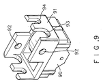
- a tube end cover 91 has threaded holes 92, and notches 93 and 94 for receiving screws 95 (see Fig. 8), whereby the tubular frame 20 can be mounted on an aluminium frame 96 of a building window 97.
- a hook-and-loop fastener with a hook side can be adhered to the back of the tubular frame 20, and a hook-and-loop fastener with a corresponding loop side (or hook side) can be adhered to the aluminum window frame 96, in order to mount the tubular frame 20 on the window frame 96.
- the hook hole 12A of the pull handle 12 can be engaged on a nail 98 on the frame 96, to hold the curtain 10 in its extended position.
- the mechanism for retracting the curtain 10 to its folded (closed) position can be the same as shown and described for the car window curtain assembly.
Landscapes
- Engineering & Computer Science (AREA)
- Structural Engineering (AREA)
- Mechanical Engineering (AREA)
- Architecture (AREA)
- Civil Engineering (AREA)
- Curtains And Furnishings For Windows Or Doors (AREA)
Description
- This invention relates to a window visor assembly, and in particular to a visor assembly for an automobile window.
- When an automobile is left unattended for a period of time with its windows closed, particularly in summertime conditions, solar rays can penetrate into the interior of the car to heat the interior to an undesired extent. A person entering the car will then experience an uncomfortably hot feeling.
- Another problem with unattended car is the possibility that a person can look into the car in search for loose items that can be stolen. Known visor units are described in US-A-4775180 and FR-A-2646205.
- The present invention provides a visor unit for installation on a window, the unit comprising:-
- a) a tubular frame having first and second ends;
- b) a foldable curtain having first and second end edges, the first end edge being secured to the tubular frame, and the second end edge being provided with a handle for exerting a pulling force on the curtain;
- c) a tension spring adapted to exert a pulling force so as to actuate the foldable curtain to open or to fold;
- d) two openings in the tubular frame, a respective one of said openings being spaced from each end of the tubular frame;
- e) a tractive tying line having two parallel runs extending from the second end edge of the curtain through the openings in the tubular frame, whereby a manual pulling force on the handle moves the foldable curtain to unfold or to close in opposition to the force of the tension spring (visor unit of the type disclosed in US-A-4 775 180); characterised by the provision of
- f) anchorage means at the first end of the tubular frame, first and second pulleys being mounted within the tubular frame at the second end thereof, a pulley seat being disposed within the tubular frame, and third and fourth pulleys being mounted on the pulley seat, whereby the tension spring is trained between the anchorage means and the pulley seat to exert a force pulling the first and second pulleys away from the third and fourth pulleys; and
- g) line anchorage means adjacent to the second end of the tubular frame, the tractive tying line further comprising line segments extending back and forth around the pulleys to the line anchorage means, whereby a manual pulling force on the handle moves the third and fourth pulleys towards the first and second pulleys in opposition to the force of the tension spring.
-
- In a preferred embodiment, the visor assembly comprises two similarly-constructed visor units each as defined above.
- Further embodiments of the invention are referred to in the dependent claims.
- The invention will now be described in greater detail, by way of example, with reference to the drawings, in which:-
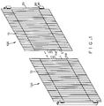
- Fig. 1 is a perspective view of a pair of curtain assemblies constructed according to the present invention;
- Fig. 2 is an exploded view of components of an assembly of Fig,. 1;
- Fig. 3 is a part-sectional end elevation of a curtain assembly of the present invention in a folded state;
- Fig. 4 is a part-sectional elevation of a curtain assembly of the of the present invention in an open state;
- Fig. 5 is an exploded view of a frame mounting mechanism used in the present invention;
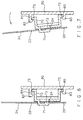
- Fig. 6 is a sectional view taken through the mounting mechanism shown in Fig. 5;
- Fig. 7 is a view similar to that of Fig. 6, but showing the mechanism in a different condition of adjustment;
- Fig. 8 is a perspective view of a curtain assembly used on a window indoors; and
- Fig. 9 is a perspective view of a mounting device used on the Fig. 8 curtain assembly.
-
- As shown in Figs. 1 and 2, there are two visor combinations or
window curtains 100 constructed according to the present invention for installation on the front and rear windshields of a car for preventing sunshine and light from entering the car interior space. The visor combination device consists of two separate butsymmetric visor devices 100 each one of which consists of afoldable visor curtain 10, a longtubular frame 20, and a tractive tying line L. One end of eachfoldable visor curtain 10 is fixed to itstubular frame 20, while the other end thereof is provided with a hook-and-loop fastener patch visor devices 100 when the respective curtains are extended across the window. Each curtain has apull handle 12 with ahole 12A designed for manually drawing the visor curtain across the window. - As shown in Fig. 2, each
tubular frame 20 is a hollow tube having upper and lower ends and two throughholes 21 spaced from the tube ends. As the two visor devices are the same, only one of them will be described in detail. Thetubular frame 20 also has two sets of mountingholes holes 21 are aligned withholes 13 in each folding strip of thevisor curtain 10 to form passages for the tractive tying line L. As shown in Fig. 4, the tractive tying line L includes two parallel runs passing through the alignedholes 13 in the foldable strips of thecurtain 10. - Referring to Figs 2 to 4, the
tubular frame 20 is provided with anupper cover 30A and alower cover 30B . Theupper cover 30A comprises arod 31 that forms an anchorage for one end of atension sprint 40. The other end of thespring 40 is anchored on apulley seat 50. Twopulleys pin 51 in thepulley seat 50. - The
lower cover 30B carries apin 32 that rotatably mounts twopulleys foldable visor curtain 10 between the extended position (Fig. 4) and the folded condition (Fig. 3). - As shown in Figs. 2, 5 and 6, the tubular frame is provided with
mounting pads pad 70 is provided with ahook structure 71 and two oppositely-facinglugs 72. Eachpad 80 is provided withflanges pockets lugs 72. A flat outer surface of eachpad 80 is provided with a double-face glue-spreadingadhesive tape 81 through which the visor device can be adhered to the windshield glass of car (not shown). - As shown in Figs 6 and 7, each
groove 84 is wider than the associated groove (pocket) 85, such that thepad 70 can pilot relative to thepad 80, whereby thepad 80 can conform to a range of different window curvatures. - As shown in Figs. 5, 6 and 7, the
pad 70 can be assembled to thetubular frame 20 by inserting thehook structure 71 into thehole 22 so that aprotuberance 73 defined by the hook structure enters into adetent hole 24 located alongside thehole 22. Eachpad 80 is pivotably adjustably connected to the associatedpad 70, via thelugs 72 and thepockets - As shown in Figs. 2 and 3, when the
visor device 100 of the present invention is folded, the tractive tying line L extends through theholes 13 in each folding strip of thevisor curtain 10 and the through theholes 21 in thetubular frame 20. Within thetubular frame 20, the tractive tying line L is integrated into a single ply to wind sequentially around thepulleys grooves 23 of the tubular frame (see Fig. 2). - As shown in Fig 3, when the
visor curtain 10 is folded, thetension spring 40 in the tubular frame is not subject to the tractive action of external force, but is in a retracted state. However, as shown in Fig. 4, when thevisor curtain 10 is to be extended, a manual force F is applied to thepull handle 12 to extend the visor curtain; the tractive tying line L is pulled out from thetubular frame tube 20 so as to draw thetension spring 40 and thepulleys pulley seat 50 downwardly, thereby to let the visor curtain extend away from the tubular frame. - The present invention consists of two symmetric similarly-constructed
visor devices 100, so that, when the twocurtains 10 are extended, the hook-and-the-loop patches visor devices 100 can be used on the front and rear windshield glass of a car to prevent sunshine being transmitted into the car, especially when the car is left unattended. - Fig. 8 shows a single curtain assembly installed on an
indoor window 97 of a building. In such an installation, it is not necessary to providemounting pads tubular frame 20. Instead,covers 91 can be provided at the ends of thetubular frame 20, and these covers are provided with mounting holes or notches. Thus, as shown in Fig.9, atube end cover 91 has threadedholes 92, andnotches tubular frame 20 can be mounted on analuminium frame 96 of abuilding window 97. Alternatively, a hook-and-loop fastener with a hook side (or a loop side) can be adhered to the back of thetubular frame 20, and a hook-and-loop fastener with a corresponding loop side (or hook side) can be adhered to thealuminum window frame 96, in order to mount thetubular frame 20 on thewindow frame 96. - When the
visor device 100 is used as the visor of theindoor window 97, thehook hole 12A of thepull handle 12 can be engaged on anail 98 on theframe 96, to hold thecurtain 10 in its extended position. The mechanism for retracting thecurtain 10 to its folded (closed) position can be the same as shown and described for the car window curtain assembly.
Claims (5)
- A visor unit for installation on a window, the unit comprising:-a) a tubular frame (20) having first and second ends;b) a foldable curtain (10) having first and second end edges, the first end edge being secured to the tubular frame, and the second end edge being provided with a handle (12) for exerting a pulling force on the curtain;c) a tension spring (40) adapted to exert a pulling force so as to actuate the foldable curtain to open or to fold;d) two openings (21) in the tubular frame, a respective one of said openings being spaced from each end of the tubular frame;e) a tractive tying line (L) having two parallel runs extending from the second end edge of the curtain through the openings in the tubular frame, whereby a manual pulling force on the handle moves the foldable curtain to unfold or to close in opposition to the force of the tension spring; characterised by the provision off) anchorage means (31) at the first end of the tubular frame, first and second pulleys (63, 64) being mounted within the tubular frame at the second end thereof, a pulley seat (50) being disposed within the tubular frame, and third and fourth pulleys (61, 62) being mounted on the pulley seat, whereby the tension spring is trained between the anchorage means and the pulley seat to exert a force pulling the first and second pulleys away from the third and fourth pulleys; andg) line anchorage means (32) adjacent to the second end of the tubular frame, the tractive tying line further comprising line segments extending back and forth around the pulleys to the line anchorage means, whereby a manual pulling force on the handle moves the third and fourth pulleys towards the first and second pulleys in opposition to the force of the tension spring.
- A visor assembly comprising two similarly-constructed visor units, each of which is as is claimed in claim 1.
- A visor assembly as claimed in claim 2, wherein the visor units are adapted for positioning on an automobile window with the tubular frames of the respective units located at the side edges of the window, so that the handles (12) on the respective units can be drawn together to pull the respective curtains (10) across the window.
- A visor assembly as claimed in claim 1 or claim 2, further comprising means for mounting the/or each tubular frame (20) on a window, the/or each mounting means comprising a pad assembly at each end of the respective tubular frame, each pad assembly comprising a first pad (70) secured to said frame, and a second pad (80) pivotally attached to the first pad, the second pad having a flat face for presentation to the surface of the window, whereby the pad assembly can be secured to the window.
- A visor assembly as claimed in claim 4, wherein the/or each first pad comprises two oppositely-extending lugs (72), and the/or each second pad comprises two facing pockets (84, 85) receiving therein the respective lugs, one of said pockets being wider than the other pocket, so that the lug in said one pocket can move back and forth to provide a pivotable adjustment of the second pad relative to the first pad.
Applications Claiming Priority (2)
| Application Number | Priority Date | Filing Date | Title |
|---|---|---|---|
| US251378 | 1994-05-31 | ||
| US08/251,378 US5477904A (en) | 1994-05-31 | 1994-05-31 | Window curtain assembly having a tension spring retraction mechanism |
Publications (2)
| Publication Number | Publication Date |
|---|---|
| EP0686519A1 EP0686519A1 (en) | 1995-12-13 |
| EP0686519B1 true EP0686519B1 (en) | 1999-03-10 |
Family
ID=22951702
Family Applications (1)
| Application Number | Title | Priority Date | Filing Date |
|---|---|---|---|
| EP95303555A Expired - Lifetime EP0686519B1 (en) | 1994-05-31 | 1995-05-25 | Visor combination device of car window |
Country Status (4)
| Country | Link |
|---|---|
| US (1) | US5477904A (en) |
| EP (1) | EP0686519B1 (en) |
| AU (1) | AU675032B2 (en) |
| DE (1) | DE69508147T2 (en) |
Cited By (2)
| Publication number | Priority date | Publication date | Assignee | Title |
|---|---|---|---|---|
| EP1783318A2 (en) | 2005-11-03 | 2007-05-09 | VKR Holding A/S | Cord tensioner for tensioning cords of shading devices and shading device |
| CN109334411A (en) * | 2018-09-05 | 2019-02-15 | 朋志鹏 | Used for summer car glass shielding sunlight device |
Families Citing this family (36)
| Publication number | Priority date | Publication date | Assignee | Title |
|---|---|---|---|---|
| US6330899B1 (en) | 1994-04-06 | 2001-12-18 | Newell Window Furnishings. Inc. | Cordless balanced window covering |
| JP3312848B2 (en) * | 1995-07-14 | 2002-08-12 | 株式会社メタコ | Screen device |
| US5778955A (en) * | 1997-06-18 | 1998-07-14 | Chen; Ing-Wen | Pleated curtain fixing device |
| DE19737263A1 (en) * | 1997-08-27 | 1999-03-04 | Schanz Hans | Roller shutter arrangement, especially for sloping roller shutter surfaces |
| US5937929A (en) * | 1997-11-06 | 1999-08-17 | Chen; Ing-Wen | Car curtain |
| US6152206A (en) * | 1999-07-14 | 2000-11-28 | Chen; Ing-Wen | Pleated curtain fastening device |
| US6644373B2 (en) * | 2001-11-08 | 2003-11-11 | Newell Window Furnishings, Inc. | Cordless blind |
| US20050051281A1 (en) * | 2002-09-09 | 2005-03-10 | Tony Lai | Multi-functional shading device |
| US6766847B1 (en) * | 2003-04-09 | 2004-07-27 | Wen-Tsan Wang | Auto-reversible folding sliding door |
| ES2413434T3 (en) * | 2004-09-03 | 2013-07-16 | Metaco Inc. | Display device |
| WO2006133556A1 (en) * | 2005-06-16 | 2006-12-21 | Screenline Innovations Inc. | Retractable screen door housing handle balancing system |
| JP4850498B2 (en) * | 2005-11-30 | 2012-01-11 | セイキ販売株式会社 | Folding screen device |
| CN101336330B (en) * | 2005-12-12 | 2012-10-31 | 澳大利亚森特股份有限公司 | A pull across roll up screen assembly |
| US7600555B2 (en) * | 2007-07-23 | 2009-10-13 | Wen-Ho Chen | Sunshade for vehicles |
| US7984745B2 (en) * | 2007-12-20 | 2011-07-26 | Nien Made Enterprise Co., Ltd. | Cordless window blind structure |
| US8365798B2 (en) * | 2008-05-27 | 2013-02-05 | Steelcase Inc. | Privacy screen assembly |
| JP5159503B2 (en) * | 2008-08-06 | 2013-03-06 | 株式会社メタコ | Screen device |
| US8220521B2 (en) * | 2008-11-22 | 2012-07-17 | Diehl Aircabin Gmbh | Device for darkening a cabin window |
| DE102009008461A1 (en) * | 2009-02-09 | 2010-08-12 | Blöcker Zweigniederlassung der Hunter Douglas Holding GmbH & Co. KG | Cord tensioning device and curtain system equipped therewith |
| US8794296B2 (en) * | 2012-03-29 | 2014-08-05 | Taiwan Bamboo Curtain Enterprise Co. Ltd. | Window blind without using a lift cord |
| TWM457502U (en) * | 2013-02-08 | 2013-07-21 | Ya-Ying Lin | Curtain |
| US8919416B2 (en) * | 2013-03-15 | 2014-12-30 | Nien Made Enterprise Co., Ltd. | Apparatus for raising and lowering covering member of window covering |
| CA2916772A1 (en) * | 2013-07-05 | 2015-01-08 | John Poppema | Concealed insect screen |
| TWM478724U (en) * | 2014-01-24 | 2014-05-21 | Taiwan Bamboo Curtain Entpr Co Ltd | Structure of window blind with no lift cord |
| CN203789657U (en) * | 2014-02-27 | 2014-08-27 | 亿丰综合工业股份有限公司 | Pulley Curtains |
| US9316050B2 (en) * | 2014-06-15 | 2016-04-19 | Ching Feng Home Fashions Co., Ltd. | Cordless curtain assembly |
| TWM496047U (en) * | 2014-06-25 | 2015-02-21 | Ching Feng Home Fashions Co | Adjusting structure of shutter body expanding length limit |
| TWM506880U (en) * | 2014-11-18 | 2015-08-11 | Ya-Ling Huang | Pull-up device without drawstring curtain |
| US10221619B2 (en) | 2015-01-21 | 2019-03-05 | Nien Made Enterprise Co., Ltd. | Lifting device of cordless covering |
| US20180023339A1 (en) * | 2015-06-05 | 2018-01-25 | Guangzhou Garden Rubber & Plastic Co., Ltd. | Cordless window covering |
| CN107636245A (en) * | 2015-06-23 | 2018-01-26 | 金懋实业有限公司 | Telescopic bathroom door |
| US9879476B2 (en) * | 2016-02-03 | 2018-01-30 | Guangzhou Garden Rubber & Plastic Co., Ltd. | Cordless curtain |
| TWM535733U (en) * | 2016-08-09 | 2017-01-21 | Ching Feng Home Fashions Co | Rope-free curtain-body drawing structure |
| USD865223S1 (en) | 2017-11-03 | 2019-10-29 | Centor Design Pty Ltd | Screen mounting tube |
| CN214330476U (en) * | 2020-11-25 | 2021-10-01 | 无锡万斯家居科技股份有限公司 | Curtain structure without stay cord |
| EP4388166A4 (en) * | 2021-08-16 | 2025-11-19 | Harper Eng Co | FLIGHT DECK BARRIER DEVICE |
Family Cites Families (9)
| Publication number | Priority date | Publication date | Assignee | Title |
|---|---|---|---|---|
| US4473101A (en) * | 1980-08-13 | 1984-09-25 | Verosol B.V. | Sun blind |
| US4557309A (en) * | 1983-08-24 | 1985-12-10 | Verosol Usa Inc. | Sun blind |
| NL8502591A (en) * | 1985-09-20 | 1987-04-16 | Schoen Siegfried Joachim | FOLDING CURTAIN. |
| US4647102A (en) * | 1986-03-03 | 1987-03-03 | Mozaffar Ebrahimzadeh | Windshield curtain |
| US4862941A (en) * | 1987-10-06 | 1989-09-05 | Hunter Douglas Inc. | Vertical shade assembly |
| US4775180A (en) * | 1987-11-10 | 1988-10-04 | Phillips Arthur J | Automatic retractable shade |
| US4838335A (en) * | 1988-11-02 | 1989-06-13 | Eskandry Ezra D | Automobile window shade convertible to horizontal expansion or vertical expansion |
| FR2646205B1 (en) * | 1989-04-25 | 1994-01-21 | Meunier Thierry | STORE ORDER BY CURSOR |
| US5269360A (en) * | 1992-06-15 | 1993-12-14 | Chen Ing Wen | Pleated blinds assembly for a car window |
-
1994
- 1994-05-31 US US08/251,378 patent/US5477904A/en not_active Expired - Fee Related
-
1995
- 1995-05-10 AU AU17955/95A patent/AU675032B2/en not_active Ceased
- 1995-05-25 EP EP95303555A patent/EP0686519B1/en not_active Expired - Lifetime
- 1995-05-25 DE DE69508147T patent/DE69508147T2/en not_active Expired - Fee Related
Cited By (5)
| Publication number | Priority date | Publication date | Assignee | Title |
|---|---|---|---|---|
| EP1783318A2 (en) | 2005-11-03 | 2007-05-09 | VKR Holding A/S | Cord tensioner for tensioning cords of shading devices and shading device |
| DE102005052895A1 (en) * | 2005-11-03 | 2007-05-24 | Vkr Holding A/S | Cord tensioner for tensioning cords on shading systems as well as shading system |
| DE102005052895B4 (en) * | 2005-11-03 | 2010-07-15 | Vkr Holding A/S | Cord tensioner for tensioning cords on shading systems |
| CN109334411A (en) * | 2018-09-05 | 2019-02-15 | 朋志鹏 | Used for summer car glass shielding sunlight device |
| CN109334411B (en) * | 2018-09-05 | 2021-07-16 | 芜湖挺优机电技术有限公司 | Used for summer car glass shielding sunlight device |
Also Published As
| Publication number | Publication date |
|---|---|
| US5477904A (en) | 1995-12-26 |
| DE69508147D1 (en) | 1999-04-15 |
| AU1795595A (en) | 1995-12-14 |
| EP0686519A1 (en) | 1995-12-13 |
| AU675032B2 (en) | 1997-01-16 |
| DE69508147T2 (en) | 1999-10-28 |
Similar Documents
| Publication | Publication Date | Title |
|---|---|---|
| EP0686519B1 (en) | Visor combination device of car window | |
| US5860466A (en) | Windshield shelter | |
| US4848827A (en) | Extensible roof for automobile | |
| US4932711A (en) | Automobile windshield shade | |
| US5605370A (en) | Window shade and vehicle window combination | |
| US4762159A (en) | Shade system | |
| US4872722A (en) | Sun roof for vehicles having protective screens | |
| US5816641A (en) | Sun shading means for cars | |
| US5031684A (en) | Vehicle windshield shade | |
| US6691762B2 (en) | Collapsible auto shade | |
| US6976523B2 (en) | Collapsible auto shade | |
| US4862942A (en) | Roller window screen | |
| US7114759B1 (en) | Vehicle windshield sunshade | |
| EP0455844A1 (en) | Sunshielding accessory for motor vehicles | |
| US5316363A (en) | Automobile window shade system | |
| US3126052A (en) | Framed shade screens for windows and various | |
| US20120256442A1 (en) | Sun protection apparatus for automobile driver or passenger | |
| US7121610B2 (en) | Combination shade and handle device | |
| KR101967538B1 (en) | Awning screens apparatus for car | |
| AU2002301996B8 (en) | Collapsible automobile shade | |
| CN2214316Y (en) | Sunshade combination device for automobile windows | |
| KR0119669Y1 (en) | Visor combination device of car window | |
| GB2334933A (en) | A blind for a vehicle mounted on or within the vehicle's sun visors | |
| US6082808A (en) | Privacy screen for a vehicle | |
| JP3006020U (en) | Awning device |
Legal Events
| Date | Code | Title | Description |
|---|---|---|---|
| PUAI | Public reference made under article 153(3) epc to a published international application that has entered the european phase |
Free format text: ORIGINAL CODE: 0009012 |
|
| AK | Designated contracting states |
Kind code of ref document: A1 Designated state(s): DE ES FR GB IT |
|
| 17P | Request for examination filed |
Effective date: 19960611 |
|
| 17Q | First examination report despatched |
Effective date: 19970401 |
|
| GRAG | Despatch of communication of intention to grant |
Free format text: ORIGINAL CODE: EPIDOS AGRA |
|
| GRAG | Despatch of communication of intention to grant |
Free format text: ORIGINAL CODE: EPIDOS AGRA |
|
| GRAH | Despatch of communication of intention to grant a patent |
Free format text: ORIGINAL CODE: EPIDOS IGRA |
|
| GRAH | Despatch of communication of intention to grant a patent |
Free format text: ORIGINAL CODE: EPIDOS IGRA |
|
| GRAA | (expected) grant |
Free format text: ORIGINAL CODE: 0009210 |
|
| AK | Designated contracting states |
Kind code of ref document: B1 Designated state(s): DE ES FR GB IT |
|
| PG25 | Lapsed in a contracting state [announced via postgrant information from national office to epo] |
Ref country code: ES Free format text: THE PATENT HAS BEEN ANNULLED BY A DECISION OF A NATIONAL AUTHORITY Effective date: 19990310 |
|
| REF | Corresponds to: |
Ref document number: 69508147 Country of ref document: DE Date of ref document: 19990415 |
|
| ET | Fr: translation filed | ||
| ITF | It: translation for a ep patent filed | ||
| PLBE | No opposition filed within time limit |
Free format text: ORIGINAL CODE: 0009261 |
|
| STAA | Information on the status of an ep patent application or granted ep patent |
Free format text: STATUS: NO OPPOSITION FILED WITHIN TIME LIMIT |
|
| 26N | No opposition filed | ||
| REG | Reference to a national code |
Ref country code: GB Ref legal event code: IF02 |
|
| PGFP | Annual fee paid to national office [announced via postgrant information from national office to epo] |
Ref country code: GB Payment date: 20020605 Year of fee payment: 8 |
|
| PGFP | Annual fee paid to national office [announced via postgrant information from national office to epo] |
Ref country code: FR Payment date: 20020617 Year of fee payment: 8 |
|
| PGFP | Annual fee paid to national office [announced via postgrant information from national office to epo] |
Ref country code: DE Payment date: 20020621 Year of fee payment: 8 |
|
| PG25 | Lapsed in a contracting state [announced via postgrant information from national office to epo] |
Ref country code: GB Free format text: LAPSE BECAUSE OF NON-PAYMENT OF DUE FEES Effective date: 20030525 |
|
| PG25 | Lapsed in a contracting state [announced via postgrant information from national office to epo] |
Ref country code: DE Free format text: LAPSE BECAUSE OF NON-PAYMENT OF DUE FEES Effective date: 20031202 |
|
| GBPC | Gb: european patent ceased through non-payment of renewal fee |
Effective date: 20030525 |
|
| PG25 | Lapsed in a contracting state [announced via postgrant information from national office to epo] |
Ref country code: FR Free format text: LAPSE BECAUSE OF NON-PAYMENT OF DUE FEES Effective date: 20040130 |
|
| REG | Reference to a national code |
Ref country code: FR Ref legal event code: ST |
|
| PG25 | Lapsed in a contracting state [announced via postgrant information from national office to epo] |
Ref country code: IT Free format text: LAPSE BECAUSE OF NON-PAYMENT OF DUE FEES;WARNING: LAPSES OF ITALIAN PATENTS WITH EFFECTIVE DATE BEFORE 2007 MAY HAVE OCCURRED AT ANY TIME BEFORE 2007. THE CORRECT EFFECTIVE DATE MAY BE DIFFERENT FROM THE ONE RECORDED. Effective date: 20050525 |